Magnetics 6 Question 17
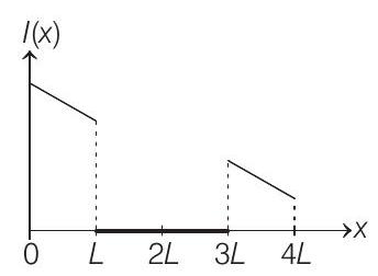
17. A rigid wire loop of square shape having side of length
(2016 Adv.)
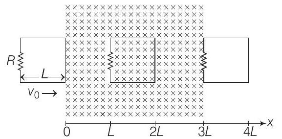
Which of the following schematic plot(s) is (are) correct? (Ignore gravity) (a)
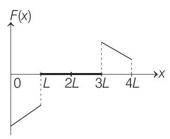
(c)
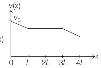
(b)
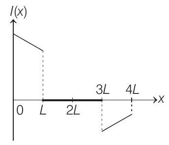
(d)
Numerical Value
Show Answer
Solution:
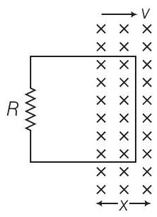
When loop was entering
(anti-clockwise)
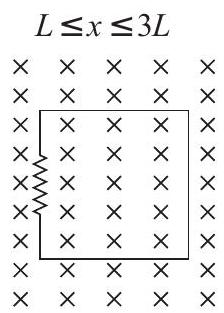
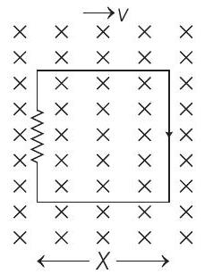
Force also will be in left direction.


