electromagnetic-induction Question 30

Question: Q. 12. The currents flowing in the two coils of selfinductance $L_{1}=16 \mathrm{mH}$ and $L_{2}=12 \mathrm{mH}$ are increasing at the same rate. If the power supplied to the two coils are equal, find the ratio of (i) induced voltages, (ii) the currents (iii) the energies stored in the two coils at a given instant.

A [Foreign 2014]

Show Answer

Solution:

Ans. (i) Induced emf (voltage) in a coil,

$$ \begin{align*} \varepsilon & =-L \frac{d I}{d t} \ \frac{\varepsilon_{1}}{\varepsilon_{2}} & =\frac{L_{1} \frac{d I}{d t}}{L_{2} \frac{d I}{d t}}=\frac{L_{1}}{L_{2}}=\frac{4}{3} \end{align*} $$

(ii) Power supplied $\quad P=\varepsilon I$

As power is same for both coils

$$ \begin{aligned} & \varepsilon_{1} I_{1}=\varepsilon_{2} I_{2} \ & \frac{I_{1}}{I_{2}}=\frac{\varepsilon_{2}}{\varepsilon_{1}}=\frac{3}{4} \end{aligned} $$

$$ \Rightarrow $$

(iii) Energy stored in a coil,

$$ \begin{aligned} U & =\frac{1}{2} L I^{2} \ \frac{U_{1}}{U_{2}} & =\frac{\frac{1}{2} L_{1} I_{1}^{2}}{\frac{1}{2} L_{2} I_{2}^{2}}=\frac{L_{1} I_{1}^{2}}{L_{2} I_{2}^{2}}=\frac{3}{4} \end{aligned} $$

[CBSE Marking Scheme 2014]

Long Answer Type Questions

[AT] Q. 1. (a) State the principle of an $a c$ generator and explain its working with the help of a labelled diagram. Obtain the expression for the emf induced in a coil having $N$ turns each of cross-sectional area $A$, rotating with a constant angular speed ’ $\omega$ ’ in a magnetic field $\vec{B}$, directed perpendicular to the axis of rotation.

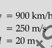
(b) An aeroplane is flying horizontally from west to east with a velocity of $900 \mathrm{~km} / \mathrm{hour}$. Calculate the potential difference developed between the ends of its wings having a span of $20 \mathrm{~m}$. The horizontal component of the Earth’s magnetic field is $5 \times 10^{-4}$ $T$ and the angle of dip is $30^{\circ}$. [CBSE SQP 2018]

Ans. (a) Principle of $a c$ generator $1 / 2$ working mark Labelled diagram

Derivation of the expression for induced emf $1 \frac{1}{2}$

(b) Calculation of potential difference $1 \frac{1}{2}$ (a)
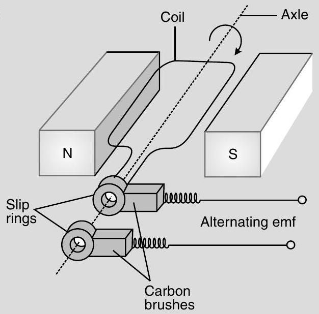
The $A C$ Generator works on the principle of electromagnetic induction.

When the magnetic flux through a coil changes, an emf is induced in it.

$1 / 2$

As the coil rotates in magnetic field the effective area of the loop, (i.e., $\mathrm{A} \cos \theta$ ) exposed to the magnetic field keeps on changing, hence magnetic flux changes and an emf is induced. $1 / 2$

$\therefore$ The induced emf, $e=-N \frac{d \phi}{d t}$

$$ \begin{aligned} & =-N B A \frac{d}{d t}(\cos \omega \mathrm{t}) \ e & =N B A \omega \sin \omega t \end{aligned} $$

(b) Potential difference developed between the ends of the wings $e=B l v$

Given:

Wing span,

$$ l=20 \mathrm{~m} $$

Vertical component of Earth’s magnetic field

$$ B_{v} \Rightarrow B_{t} \tan \delta $$

$\therefore$ Potential difference,

$$ =5 \times 10^{-4}\left(\tan 30^{\circ}\right) \text { tesla } 1 / 2 $$

$$ \varepsilon=5 \times 10^{-4}\left(\tan 30^{\circ}\right) \times 20 \times 250 $$

$$ =\frac{5 \times 20 \times 250 \times 10^{-4}}{\sqrt{3}} $$

$=1.44$ volt

$1 / 2$

[CBSE Marking Scheme 2018]

Answering Tips

  • While answering the question related to ac generator always remember to make a proper and labelled diagram following with explanation of principle, construction and working of generator.

Detailed Answer :

(a) A.C. generator :

A.C. generator is a device which converts mechanical energy into electric energy.

Principle : It works on the principle of electromagnetic induction.

Working : It consists of

(i) Armature coil of large number of turns of copper wire wound over soft iron core soft iron core is used to increase magnetic flux. (ii) Field magnets are used to apply magnetic field in which armature coil is rotated with its axis perpendicular to field lines.

(iii) Slip rings used to provide movable contacts of armature coil with external circuit containing load.

(iv) Brushes are the metallic pieces used to pass an electric current from armature coil to the external circuit containing load.
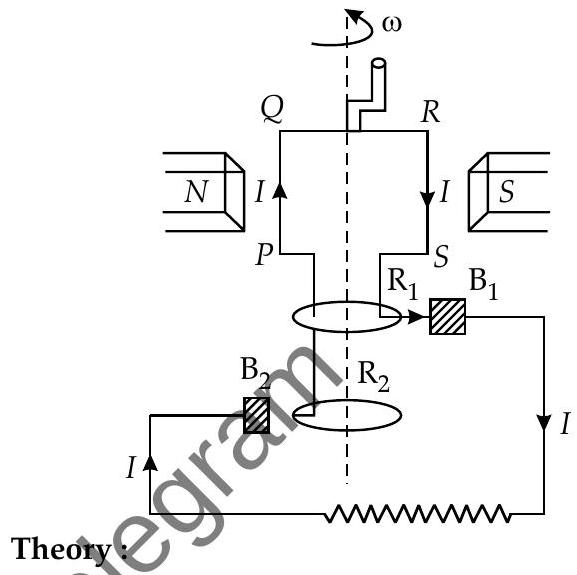
$1 / 2$

CorSider a coil PQRS free to rotate in a uniform magnetic field $\vec{B}$. The initial flux through the coil is maximum i.e., $\phi=B A$ but as the coil is rotating with angular velocity $\omega$, at any instant ’ $t$ ’ the flux is given by
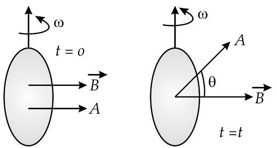
$$ \phi=B A \cos \theta=B A \cos \omega t $$

As the coil rotates, the magnetic flux linked with it changes. An induced emf is set up in the coil which is given by,

$\varepsilon=\frac{d \phi}{d t}=-\frac{d}{d t}(B A \cos \omega t)=\omega B A \sin \omega t$

$1 / 2$

If the coil has $N$ turns, then the total induced emf will be

$$ \varepsilon=N B A \omega \sin t . $$

Thus, the induced emf varies sinusoidally with time ’ $t$ ‘. The value of induced emf is maximum when $\sin \omega t=1$ or $\sin \omega t=90^{\circ}$, i.e., when the plane of the coil parallel to the field $\vec{B}$. Denoting this maximum value by $\varepsilon_{0}$, we have

$$ \varepsilon_{0}=N B A \omega $$

$\varepsilon=\varepsilon_{0} \sin \omega t=\sin 2 \pi f t$ where $f$ is the frequency of rotation of the coil.

We consider the following special cases :

(i) When $\omega t=0^{\circ}$, the plane of the coil is perpendicular to $B, \sin \omega t=\sin 0^{\circ}$ so that $\varepsilon=0$

(ii) When $\omega t=\pi / 2$, the plane of coil is parallel to field

$B, \sin \omega t=\sin \pi / 2=1$, so that $\varepsilon=\varepsilon_{0}$ (iii) When $\omega t=\pi$, the plane of the coil is again perpendicular to $B, \sin \omega t=\sin \pi=0$ so that $\varepsilon=0$

(iv) When $\omega t=\frac{3 \pi}{2}$, the plane of the coil is again parallel to $B, \sin \omega t-\sin \frac{3 \pi}{2}=-1$ so that $\varepsilon=-\varepsilon_{0}$

(v) When $\omega=2 \pi$, the plane of the coil again becomes perpendicular to $B$ after completing one rotation, $\sin \omega t=\sin 2 \pi=0$ so that $\varepsilon=0$.

As the coil continues to rotate in the same sense the same cycle of changes repeats again and again. Such an emf is called sinusoidal or alternating emf. Both the magnitude and direction of this emf changes regularly with time.

  • The fact that an induced emf is set up in a coil when rotated a magnetic field forms the basic principle of a dynamo or a generator.
  • The electric current produced varies sinusoidally with time, so is known as ‘alternating current’ and hence the generator is known as ‘A.C. generator’ .

(b) As

$$ \begin{aligned} \frac{B_{V}}{B_{H}} & =\tan \delta \ B_{V} & =B_{H} \tan \delta \ & =5 \times 10^{-4} \tan 30^{\circ} \ & =\frac{5 \times 10^{-4}}{\sqrt{3}} \ e & =B l v \ & =\frac{5 \times 10^{-4}}{\sqrt{3}} \times 20 \times 250 \ & =1.44 \mathrm{~V} \end{aligned} $$

$1 / 2$


Table of Contents

NCERT Chapter Video Solution

Dual Pane