current-electricity Question 46
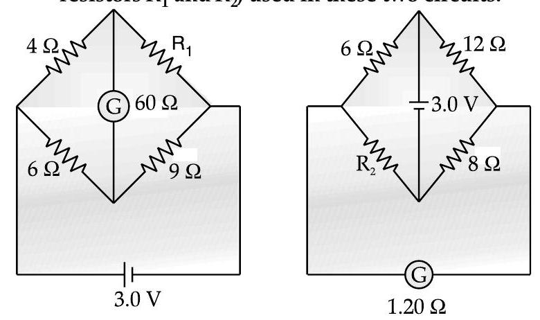
Question: Q. 7. The galvanometer, in each of the two given circuits, does not show any deflection. Find the ratio of the resistors $R_{1}$ and $R_{2}$, used in these two circuits.
A [CBSE SQP 2013]
Show Answer
Solution:
Ans. For circuit 1, we have, (from the Wheatstone bridge balance condition),
$$ \begin{aligned} \frac{4}{R_{1}} & =\frac{6}{9} \ R_{1} & =6 \Omega \end{aligned} $$
In circuit 2, the interchange of the positions of the battery and the galvanometer, does not change the (Wheatstone Bridge) balance condition.
$$ \begin{array}{ll} \therefore & \frac{R_{2}}{8}=\frac{6}{12} \ \text { or } & R_{2}=4 \Omega \ \therefore & \frac{R_{1}}{R_{2}}=\frac{6}{4}=\frac{3}{2} \end{array} $$
$$ \text { or } \quad R_{2}=4 \Omega \quad 1 / 2 $$
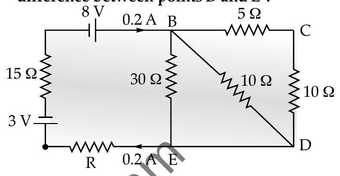
[AI Q. 8. Calculate the value of the resistance $R$ in the circuit shown in the figure so that the current in the circuit is $0.2 \mathrm{~A}$. What would be the potential difference between points $B$ and $E$ ?
A [O.D. I, II, III 2012]
Ans.
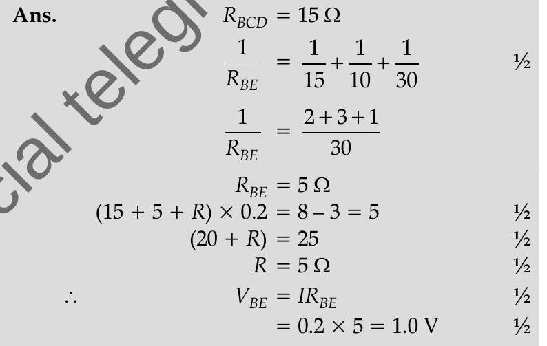
$$ \frac{1}{R_{B E}}=\frac{1}{15}+\frac{1}{10}+\frac{1}{30} $$
$$ \begin{array}{rlr} \frac{1}{R_{B E}} & =\frac{2+3+1}{30} & \ R_{B E} & =5 \Omega & \ (15+5+R) \times 0.2 & =8-3=5 & 1 / 2 \ (20+R) & =25 & 1 / 2 \ R & =5 \Omega & 1 / 2 \ V_{B E} & =I R_{B E} & 1 / 2 \ & =0.2 \times 5=1.0 \mathrm{~V} & 1 / 2 \end{array} $$
$$ x $$
$$ \text { ‘2 } $$
Long Answer Type Questions
[AI Q. 1. (i) State the two Kirchhoff’s laws. Explain briefly how these rules are justified.
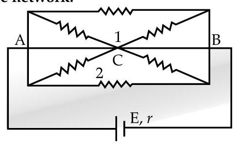
(ii) The current is drawn from a cell of emf $E$ and internal resistance $r$ connected to the network of resistors each of resistance $r$ as shown in the figure. Obtain the expression for (i) the current drawn from the cell and (ii) the power consumed in the network.
R [Delhi Compt I, II, III 2017]
Ans. (i) Try yourself Similar to Q. 1, Short Answer Type Question-I
(ii) Equivalent resistance of the loop
$$ R=\frac{r}{3} $$
[CBSE Marking Scheme, 2012]
Hence current drawn from the cell
$$ \mathrm{I}=\frac{E}{\frac{r}{3}+r}=\frac{3 E}{4 r} $$
Power consumed, $\quad P=I^{2} R$
$$ \begin{aligned} & =\frac{9 E^{2}}{16 r^{2}} \times \frac{4 r}{3} \ & =\frac{3 E^{2}}{4 r} \end{aligned} $$
$$ \begin{aligned} \frac{1}{R_{1}} & =\frac{1}{r}+\frac{1}{2 r} \ \frac{1}{R_{1}} & =\frac{2+1}{2 r} \ \therefore \quad R_{1} & =\frac{2 r}{3} \end{aligned} $$
Further since both mesh 1 and 2 are similar,
$$ \therefore \quad R_{2}=\frac{2 r}{3} $$
Now combining resistances $R_{1}$ and $R_{2}$, we get :
$$ \begin{aligned} \frac{1}{R} & =\frac{1}{R_{1}}+\frac{1}{R_{2}} \ \therefore \quad \frac{1}{R} & =\frac{1}{\frac{2 r}{3}}+\frac{1}{\frac{2 r}{3}} \end{aligned} $$
(As $R_{1}|| R_{2}$ )
1
$$ \begin{equation*} \therefore \quad R=\frac{r}{3} \tag{1} \end{equation*} $$
As the circuit is in series with internal resistance, then resultant resistance will be :
$$ r^{\prime}=r+\frac{r}{3}=\frac{4 r}{3} $$
Hence the current drawn from the cell will be :
$$ \begin{equation*} I=\frac{E}{r^{\prime}}=\frac{3 E}{4 r} \tag{1} \end{equation*} $$
Now power consumed by the network :
$$ P=I^{2} r^{\prime} $$
$$ =\left(\frac{3 E}{4 r}\right)^{2} \times \frac{4 r}{3} $$
$\therefore$ Power, $\quad P=\frac{3 E^{2}}{4 r}$