Ray Optics and Optical Instruments
9.1 INTRODUCTION
Nature has endowed the human eye (retina) with the sensitivity to detect electromagnetic waves within a small range of the electromagnetic spectrum. Electromagnetic radiation belonging to this region of the spectrum (wavelength of about
There are two things that we can intuitively mention about light from common experience. First, that it travels with enormous speed and second, that it travels in a straight line. It took some time for people to realise that the speed of light is finite and measurable. Its presently accepted value in vacuum is
The intuitive notion that light travels in a straight line seems to contradict what we have learnt in Chapter 8, that light is an electromagnetic wave of wavelength belonging to the visible part of the spectrum. How to reconcile the two facts? The answer is that the wavelength of light is very small compared to the size of ordinary objects that we encounter commonly (generally of the order of a few
In this chapter, we consider the phenomena of reflection, refraction and dispersion of light, using the ray picture of light. Using the basic laws of reflection and refraction, we shall study the image formation by plane and spherical reflecting and refracting surfaces. We then go on to describe the construction and working of some important optical instruments, including the human eye.
9.2 Reflection of Light by Spherical Mirrors

FIGURE 9.1 The incident ray, reflected ray and the normal to the reflecting surface lie in the same plane.
We are familiar with the laws of reflection. The angle of reflection (i.e., the angle between reflected ray and the normal to the reflecting surface or the mirror) equals the angle of incidence (angle between incident ray and the normal). Also that the incident ray, reflected ray and the normal to the reflecting surface at the point of incidence lie in the same plane (Fig. 9.1). These laws are valid at each point on any reflecting surface whether plane or curved. However, we shall restrict our discussion to the special case of curved surfaces, that is, spherical surfaces. The normal in this case is to be taken as normal to the tangent to surface at the point of incidence. That is, the normal is along the radius, the line joining the centre of curvature of the mirror to the point of incidence.
We have already studied that the geometric centre of a spherical mirror is called its pole while that of a spherical lens is called its optical centre. The line joining the pole and the centre of curvature of the spherical mirror is known as the principal axis. In the case of spherical lenses, the principal axis is the line joining the optical centre with its principal focus as you will see later.

FIGURE 9.2 The Cartesian Sign Convention.
9.2.1 Sign convention
To derive the relevant formulae for reflection by spherical mirrors and refraction by spherical lenses, we must first adopt a sign convention for measuring distances. In this book, we shall follow the Cartesian sign convention. According to this convention, all distances are measured from the pole of the mirror or the optical centre of the lens. The distances measured in the same direction as the incident light are taken as positive and those measured in the direction opposite to the direction of incident light are taken as negative (Fig. 9.2).
principal axis (
The heights measured downwards are taken as negative.
With a common accepted convention, it turns out that a single formula for spherical mirrors and a single formula for spherical lenses can handle all different cases.
9.2.2 Focal length of spherical mirrors
Figure 9.3 shows what happens when a parallel beam of light is incident on (a) a concave mirror, and (b) a convex mirror. We assume that the rays are paraxial, i.e., they are incident at points close to the pole

(c)
FIGURE 9.3 Focus of a concave and convex mirror.
The distance between the focus
Let

FIGURE 9.4 Geometry of reflection of an incident ray on (a) concave spherical mirror, and (b) convex spherical mirror.

FIGURE 9.5 Ray diagram for image formation by a concave mirror.
Now, be the perpendicular from
For small
or,
Now, for small
9.2.3 The mirror equation
If rays emanating from a point actually meet at another point after reflection and/or refraction, that point is called the image of the first point. The image is real if the rays actually converge to the point; it is virtual if the rays do not actually meet but appear to diverge from the point when produced backwards. An image is thus a point-to-point correspondence with the object established through reflection and/or refraction.
In principle, we can take any two rays emanating from a point on an object, trace their paths, find their point of intersection and thus, obtain the image of the point due to reflection at a spherical mirror. In practice, however, it is convenient to choose any two of the following rays:
(i) The ray from the point which is parallel to the principal axis. The reflected ray goes through the focus of the mirror.
(ii) The ray passing through the centre of curvature of a concave mirror or appearing to pass through it for a convex mirror. The reflected ray simply retraces the path.
(iii) The ray passing through (or directed towards) the focus of the concave mirror or appearing to pass through (or directed towards) the focus of a convex mirror. The reflected ray is parallel to the principal axis.
(iv) The ray incident at any angle at the pole. The reflected ray follows laws of reflection.
Figure 9.5 shows the ray diagram considering three rays. It shows the image
We now derive the mirror equation or the relation between the object distance
From Fig. 9.5, the two right-angled triangles
Since
Comparing Eqs. (9.4) and (9.5), we get
Equation (9.6) is a relation involving magnitude of distances. We now apply the sign convention. We note that light travels from the object to the mirror MPN. Hence this is taken as the positive direction. To reach the object
Using these in Eq. (9.6), we get
or
Dividing it by
This relation is known as the mirror equation.
The size of the image relative to the size of the object is another important quantity to consider. We define linear magnification
With the sign convention, this becomes
so that
We have derived here the mirror equation, Eq. (9.7), and the magnification formula, Eq. (9.9), for the case of real, inverted image formed by a concave mirror. With the proper use of sign convention, these are, in fact, valid for all the cases of reflection by a spherical mirror (concave or convex) whether the image formed is real or virtual. Figure 9.6 shows the ray diagrams for virtual image formed by a concave and convex mirror. You should verify that Eqs. (9.7) and (9.9) are valid for these cases as well.

FIGURE 9.6 Image formation by (a) a concave mirror with object between
Example 9.1 Suppose that the lower half of the concave mirror’s reflecting surface in Fig. 9.6 is covered with an opaque (non-reflective) material. What effect will this have on the image of an object placed in front of the mirror?
Solution You may think that the image will now show only half of the object, but taking the laws of reflection to be true for all points of the remaining part of the mirror, the image will be that of the whole object. However, as the area of the reflecting surface has been reduced, the intensity of the image will be low (in this case, half).
Example 9.2 A mobile phone lies along the principal axis of a concave mirror, as shown in Fig. 9.7. Show by suitable diagram, the formation of its image. Explain why the magnification is not uniform. Will the distortion of image depend on the location of the phone with respect to the mirror?

FIGURE 9.7
Solution
The ray diagram for the formation of the image of the phone is shown in Fig. 9.7. The image of the part which is on the plane perpendicular to principal axis will be on the same plane. It will be of the same size, i.e.,
Example 9.3 An object is placed at (i)
Solution
The focal length
(i) The object distance
The image is
Also, magnification
The image is magnified, real and inverted.
(ii) The object distance
This image is formed at
The image is magnified, virtual and erect.
Example 9.4 Suppose while sitting in a parked car, you notice a jogger approaching towards you in the side view mirror of
Solution
From the mirror equation, Eq. (9.7), we get
For convex mirror, since
for
Since the jogger moves at a constant speed of
The shift in the position of image in
Therefore, the average speed of the image when the jogger is between
Similarly, it can be seen that for
Although the jogger has been moving with a constant speed, the speed of his/her image appears to increase substantially as he/she moves closer to the mirror. This phenomenon can be noticed by any person sitting in a stationary car or a bus. In case of moving vehicles, a similar phenomenon could be observed if the vehicle in the rear is moving closer with a constant speed.
9.3 Refraction
When a beam of light encounters another transparent medium, a part of light gets reflected back into the first medium while the rest enters the other. A ray of light represents a beam. The direction of propagation of an obliquely incident
(1)

FIGURE 9.8 Refraction and reflection of light. (i) The incident ray, the refracted ray and the normal to the interface at the point of incidence, all lie in the same plane.
(ii) The ratio of the sine of the angle of incidence to the sine of angle of refraction is constant. Remember that the angles of incidence
where
From Eq. (9.10), if
Note: Optical density should not be confused with mass density, which is mass per unit volume. It is possible that mass density of an optically denser medium may be less than that of an optically rarer medium (optical density is the ratio of the speed of light in two media). For example, turpentine and water. Mass density of turpentine is less than that of water but its optical density is higher.
If
It also follows that if
Some elementary results based on the laws of refraction follow immediately. For a rectangular slab, refraction takes place at two interfaces (airglass and glass-air). It is easily seen from Fig. 9.9 that
9.4 Total Internal Reflection
When light travels from an optically denser medium to a rarer medium at the interface, it is partly reflected back into the same medium and partly refracted to the second medium. This reflection is called the internal reflection.
When a ray of light enters from a denser medium to a rarer medium, it bends away from the normal, for example, the ray

FIGURE 9.11 Refraction and internal reflection of rays from a point
no transmission of light takes place.
The angle of incidence corresponding to an angle of refraction
For values of
The refractive index of denser medium 1 with respect to rarer medium 2 will be
Table 9.1 Critical angle of some transparent media with Respect to air
| Substance medium | Refractive index | Critical angle |
|---|---|---|
| Water | 1.33 | 48.75 |
| Crown glass | 1.52 | 41.14 |
| Dense flint glass | 1.62 | 37.31 |
| Diamond | 2.42 | 24.41 |
A demonstration for total internal reflection
All optical phenomena can be demonstrated very easily with the use of a laser torch or pointer, which is easily available nowadays. Take a glass beaker with clear water in it. Add a few drops of milk or any other suspension to water and stir so that water becomes a little turbid. Take a laser pointer and shine its beam through the turbid water. You will find that the path of the beam inside the water shines brightly.
Shine the beam from below the beaker such that it strikes at the upper water surface at the other end. Do you find that it undergoes partial reflection (which is seen as a spot on the table below) and partial refraction [which comes out in the air and is seen as a spot on the roof; Fig. 9.12(a)]? Now direct the laser beam from one side of the beaker such that it strikes the upper surface of water more obliquely [Fig. 9.12(b)]. Adjust the direction of laser beam until you find the angle for which the refraction above the water surface is totally absent and the beam is totally reflected back to water. This is total internal reflection at its simplest.
Pour this water in a long test tube and shine the laser light from top, as shown in Fig. 9.12(c). Adjust the direction of the laser beam such that it is totally internally reflected every time it strikes the walls of the tube. This is similar to what happens in optical fibres.
Take care not to look into the laser beam directly and not to point it at anybody’s face.
9.4.1 Total internal reflection in nature and its technelogical applications
(i) Prism: Prisms designed to bend light by
In the first two cases, the critical angle
(ii) Optical fibres: Nowadays optical fibres are extensively used for transmitting audio and video signals through long distances. Optical fibres too make use of the phenomenon of total internal reflection. Optical fibres are fabricated with high quality composite glass/quartz fibres. Each fibre consists of a core and cladding. The refractive index of the material of the core is higher than that of the cladding.
When a signal in the form of light is directed at one end of the fibre at a suitable angle, it undergoes repeated total internal reflections along the length of the fibre and finally comes out at the other end (Fig. 9.14). Since light undergoes total internal reflection at each stage, there is no appreciable loss in the intensity of the light signal. Optical fibres are fabricated such that light reflected at one side of inner surface strikes the other at an angle larger than the critical angle. Even if the fibre is bent, light can easily travel along its length. Thus, an optical fibre can be used to act as an optical pipe.
A bundle of optical fibres can be put to several uses. Optical fibres are extensively used for transmitting and receiving

FIGURE 9.12
Observing total internal reflection in water with a laser beam (refraction due to glass of beaker neglected being very thin).

FIGURE 9.13 Prisms designed to bend rays by
231

FIGURE 9.14 Light undergoes successive total internal reflections as it moves through an optical fibre. electrical signals which are converted to light by suitable transducers. Obviously, optical fibres can also be used for transmission of optical signals. For example, these are used as a ’light pipe’ to facilitate visual examination of internal organs like esophagus, stomach and intestines. You might have seen a commonly available decorative lamp with fine plastic fibres with their free ends forming a fountain like structure. The other end of the fibres is fixed over an electric lamp. When the
lamp is switched on, the light travels from the bottom of each fibre and appears at the tip of its free end as a dot of light. The fibres in such decorative lamps are optical fibres.
The main requirement in fabricating optical fibres is that there should be very little absorption of light as it travels for long distances inside them. This has been achieved by purification and special preparation of materials such as quartz. In silica glass fibres, it is possible to transmit more than
9.5 Refraction at Spherical Surfaces And By Lenses
We have so far considered refraction at a plane interface. We shall now consider refraction at a spherical interface between two transparent media. An infinitesimal part of a spherical surface can be regarded as planar and the same laws of refraction can be applied at every point on the surface. Just as for reflection by a spherical mirror, the normal at the point of incidence is perpendicular to the tangent plane to the spherical surface at that point and, therefore, passes through its centre of curvature. We first consider refraction by a single spherical surface and follow it by thin lenses. A thin lens is a transparent optical medium bounded by two surfaces; at least one of which should be spherical. Applying the formula for image formation by a single spherical surface successively at the two surfaces of a lens, we shall obtain the lens maker’s formula and then the lens formula.
9.5.1 Refraction at a spherical surface
Figure 9.15 shows the geometry of formation of image
Now, for
Similarly,
i.e.,
Now, by Snell’s law
or for small angles
Substituting

FIGURE 9.15 Refraction at a spherical surface separating two media.
Here, OM, MI and MC represent magnitudes of distances. Applying the Cartesian sign convention,
Substituting these in Eq. (9.15), we get
Equation (9.16) gives us a relation between object and image distance in terms of refractive index of the medium and the radius of curvature of the curved spherical surface. It holds for any curved spherical surface.
Example 9.5 Light from a point source in air falls on a spherical glass surface (
Solution
We use the relation given by Eq. (9.16). Here
We then have
or
The image is formed at a distance of
9.5.2 Refraction by a lens
Figure 9.16(a) shows the geometry of image formation by a double convex lens. The image formation can be seen in terms of two steps: (i) The first refracting surface forms the image

FIGURE 9.16 (a) The position of object, and the image formed by a double convex lens,
(b) Refraction at the first spherical surface and
(c) Refraction at the second spherical surface.
A similar procedure applied to the second interface*
For a thin lens,
Suppose the object is at infinity, i.e.,
The point where image of an object placed at infinity is formed is called the focus
So Eq. (9.20) can be written as
Equation (9.21) is known as the lens maker’s formula. It is useful to design lenses of desired focal length using surfaces of suitable radii of curvature. Note that the formula is true for a concave lens also. In that case
- Note that now the refractive index of the medium on the right side of ADC is
From Eqs. (9.19) and (9.20), we get
Again, in the thin lens approximation, B and D are both close to the optical centre of the lens. Applying the sign convention,
Equation (9.23) is the familiar thin lens formula. Though we derived it for a real image formed by a convex lens, the formula is valid for both convex as well as concave lenses and for both real and virtual images.
It is worth mentioning that the two foci,
To find the image of an object by a lens, we can, in principle, take any two rays emanating from a point on an object; trace their paths using the laws of refraction and find the point where the refracted rays meet (or appear to meet). In practice, however, it is convenient to choose any two of the following rays:
(i) A ray emanating from the object parallel to the principal axis of the lens after refraction passes through the second principal focus
(ii) A ray of light, passing through the optical centre of the lens, emerges without any deviation after refraction.
(iii) (a) A ray of light passing through the first principal focus of a convex lens [Fig. 9.17(a)] emerges parallel to the principal axis after refraction.
(b) A ray of light incident on a concave lens appearing to meet the principal axis at second focus point emerges parallel to the principal axis after refraction [Fig. 9.17(b)].
Figures 9.17(a) and (b) illustrate these rules for a convex and a concave lens, respectively. You should practice drawing similar ray diagrams for different positions of the object with respect to the lens and also verify that the lens formula, Eq. (9.23), holds good for all cases.
Here again it must be remembered that each point on an object gives out infinite number of rays. All these rays will pass through the same image point after refraction at the lens.
Magnification
![]()
FIGURE 9.17 Tracing rays through (a) convex lens (b) concave lens. in the same way as for spherical mirrors, it is easily seen that for a lens
When we apply the sign convention, we see that, for erect (and virtual) image formed by a convex or concave lens,
Example 9.6 A magician during a show makes a glass lens with
Solution
The refractive index of the liquid must be equal to 1.47 in order to make the lens disappear. This means

FIGURE 9.18 Power of a lens.
9.5.3 Power of a lens
Power of a lens is a measure of the convergence or divergence, which a lens introduces in the light falling on it. Clearly, a lens of shorter focal length bends the incident light more, while converging it in case of a convex lens and diverging it in case of a concave lens. The power
value of
The SI unit for power of a lens is dioptre (D):
Example 9.7 (i) If
Solution
(i) Power
(ii) Here, we have
Refractive index of air is taken as unity.
We use the lens formula of Eq. (9.22). The sign convention has to be applied for
Substituting the values, we have
This gives
(iii) For a glass lens in air,
For the same glass lens in water,
Combining these two equations, we find
9.5.4 Combination of thin lenses in contact
Consider two lenses

FIGURE 9.19 Image formation by a combination of two thin lenses in contact. the angle at which they strike the second lens. Since the lenses are thin, we assume the optical centres of the lenses to be coincident. Let this central point be denoted by
For the image formed by the first lens
For the image formed by the second lens B, we get
Adding Eqs. (9.27) and (9.28), we get
If the two lens-system is regarded as equivalent to a single lens of focal length
so that we get
The derivation is valid for any number of thin lenses in contact. If several thin lenses of focal length
In terms of power, Eq. (9.31) can be written as
where
Such a system of combination of lenses is commonly used in designing lenses for cameras, microscopes, telescopes and other optical instruments.
Example 9.8 Find the position of the image formed by the lens combination given in the Fig. 9.20.

FIGURE 9.20
Solution Image formed by the first lens
or
The image formed by the first lens serves as the object for the second. This is at a distance of
or
The virtual image is formed at an infinite distance to the left of the second lens. This acts as an object for the third lens.
or
or
The final image is formed
9.6 Refraction through a Prism
Figure 9.21 shows the passage of light through a triangular prism
In the quadrilateral AQNR, two of the angles (at the vertices

FIGURE 9.21 A ray of light passing through a triangular glass prism.
From the triangle
Comparing these two equations, we get
The total deviation
that is,
Thus, the angle of deviation depends on the angle of incidence. A plot between the angle of deviation and angle of incidence is shown in Fig. 9.22. You can see that, in general, any given value of

FIGURE 9.22 Plot of angle of deviation (
Equation (9.34) gives
In the same way, Eq. (9.35) gives
The refractive index of the prism is
The angles
For a small angle prism, i.e., a thin prism,
It implies that, thin prisms do not deviate light much.
9.7 OPTICAL INSTRUMENTS
A number of optical devices and instruments have been designed utilising reflecting and refracting properties of mirrors, lenses and prisms. Periscope, kaleidoscope, binoculars, telescopes, microscopes are some examples of optical devices and instruments that are in common use. Our eye is, of course, one of the most important optical device the nature has endowed us with. We have already studied about the human eye in Class X. We now go on to describe the principles of working of the microscope and the telescope.
9.7.1 The microscope
A simple magnifier or microscope is a converging lens of small focal length (Fig. 9.23). In order to use such a lens as a microscope, the lens is held near the object, one focal length away or less, and the eye is positioned close to the lens on the other side. The idea is to get an erect, magnified and virtual image of the object at a distance so that it can be viewed comfortably, i.e., at

Eye focussed at infinity
FIGURE 9.23 A simple microscope; (a) the magnifying lens is located such that the image is at the near point, (b) the angle subtanded by the object, is the same as that at the near point, and (c) the object near the focal point of the lens; the image is far off but closer than infinity.
than the focal length of the lens, the image is virtual and closer than infinity. Although the closest comfortable distance for viewing the image is when it is at the near point (distance
The linear magnification
Now according to our sign convention,
Since
Note that
We will now find the magnification when the image is at infinity. In this case we will have to obtained the angular magnification. Suppose the object has a height
We now find the angle subtended at the eye by the image when the object is at
we have the angle subtended by the image
as is clear from Fig. 9.23(c). The angular magnification is, therefore
This is one less than the magnification when the image is at the near point, Eq. (9.39), but the viewing is more comfortable and the difference in magnification is usually small. In subsequent discussions of optical instruments (microscope and telescope) we shall assume the image to be at infinity.

FIGURE 9.24 Ray diagram for the formation of image by a compound microscope.
A simple microscope has a limited maximum magnification
We now obtain the magnification due to a compound microscope. The ray diagram of Fig. 9.24 shows that the (linear) magnification due to the objective, namely
where we have used the result
Here
As the first inverted image is near the focal point of the eyepiece, we use the result from the discussion above for the simple microscope to obtain the (angular) magnification
When the final image is formed at infinity, the angular magnification due to the eyepiece [Eq. (9.42)] is
Thus, the total magnification [according to Eq. (9.33)], when the image is formed at infinity, is
Clearly, to achieve a large magnification of a small object (hence the name microscope), the objective and eyepiece should have small focal lengths. In practice, it is difficult to make the focal length much smaller than
For example, with an objective with
Various other factors such as illumination of the object, contribute to the quality and visibility of the image. In modern microscopes, multicomponent lenses are used for both the objective and the eyepiece to improve image quality by minimising various optical aberrations (defects) in lenses.
9.7.2 Telescope
The telescope is used to provide angular magnification of distant objects (Fig. 9.25). It also has an objective and an eyepiece. But here, the objective has a large focal length and a much larger aperture than the eyepiece. Light from a distant object enters the objective and a real image is formed in the tube at its second focal point. The eyepiece magnifies this image producing a final inverted image. The magnifying power
In this case, the length of the telescope tube is
Terrestrial telescopes have, in addition, a pair of inverting lenses to make the final image erect. Refracting telescopes can be used both for terrestrial and astronomical observations. For example, consider a telescope whose objective has a focal length of
Let us consider a pair of stars of actual separation 1’ (one minute of arc). The stars appear as though they are separated by an angle of

FIGURE 9.25 A refracting telescope.
The main considerations with an astronomical telescope are its light gathering power and its resolution or resolving power. The former clearly depends on the area of the objective. With larger diameters, fainter objects can be observed. The resolving power, or the ability to observe two objects distinctly, which are in very nearly the same direction, also depends on the diameter of the objective. So, the desirable aim in optical telescopes is to make them with objective of large diameter. The largest lens objective in use has a diameter of
For these reasons, modern telescopes use a concave mirror rather than a lens for the objective. Telescopes with mirror objectives are called reflecting telescopes. There is no chromatic aberration in a mirror. Mechanical support is much less of a problem since a mirror weighs much less than a lens of equivalent optical quality, and can be supported over its entire back surface, not just over its rim. One obvious problem with a reflecting telescope is that the objective mirror focusses light inside

FIGURE 9.26 Schematic diagram of a reflecting telescope (Cassegrain).
the telescope tube. One must have an eyepiece and the observer right there, obstructing some light (depending on the size of the observer cage). This is what is done in the very large 200 inch ( 5.08 m) diameters, Mt. Palomar telescope, California. The viewer sits near the focal point of the mirror, in a small cage. Another solution to the problem is to deflect the light being focussed by another mirror. One such arrangement using a convex secondary mirror to focus the incident light, which now passes through a hole in the objective primary mirror, is shown in Fig. 9.26. This is known as a Cassegrain telescope, after its inventor. It has the advantages of a large focal length in a short telescope. The largest telescope in India is in Kavalur, Tamil Nadu. It is a
SUMMARY
1. Reflection is governed by the equation
2. The critical angle of incidence
3. Cartesian sign convention: Distances measured in the same direction as the incident light are positive; those measured in the opposite direction are negative. All distances are measured from the pole/optic centre of the mirror/lens on the principal axis. The heights measured upwards above
4. Mirror equation:
where
5. For a prism of the angle
where
6. For refraction through a spherical interface (from medium 1 to 2 of refractive index
Thin lens formula
Lens maker’s formula
The SI unit for power of a lens is dioptre (D):
If several thin lenses of focal length
The total power of a combination of several lenses is
7. Dispersion is the splitting of light into its constituent colour.
8. Magnifying power
where
9. Magnifying power
where
POINTS TO PONDER
1. The laws of reflection and refraction are true for all surfaces and pairs of media at the point of the incidence.
2. The real image of an object placed between
3. Image formation needs regular reflection/refraction. In principle, all rays from a given point should reach the same image point. This is why you do not see your image by an irregular reflecting object, say the page of a book.
4. Thick lenses give coloured images due to dispersion. The variety in colour of objects we see around us is due to the constituent colours of the light incident on them. A monochromatic light may produce an entirely different perception about the colours on an object as seen in white light.
5. For a simple microscope, the angular size of the object equals the angular size of the image. Yet it offers magnification because we can keep the small object much closer to the eye than
EXERCISES
9.1 A small candle,
Show Answer
Answer
Size of the candle,
Image size
Object distance,
Radius of curvature of the concave mirror,
Focal length of the concave mirror,
Image distance
The image distance can be obtained using the mirror formula:
Therefore, the screen should be placed
The magnification of the image is given as:
The height of the candle’s image is
If the candle is moved closer to the mirror, then the screen will have to be moved away from the mirror in order to obtain the image.
Show Answer
Answer
Height of the needle,
Object distance,
Focal length of the convex mirror,
Image distance
The value of
Hence, the image of the needle is
The image size is given by the magnification formula:
Hence, magnification of the image,
The height of the image is
If the needle is moved farther from the mirror, the image will also move away from the mirror, and the size of the image will reduce gradually.
Show Answer
Answer
Actual depth of the needle in water,
Apparent depth of the needle in water,
Refractive index of water
The value of
Hence, the refractive index of water is about 1.33.
Water is replaced by a liquid of refractive index,
The actual depth of the needle remains the same, but its apparent depth changes. Let
Hence, the new apparent depth of the needle is
FIGURE 9.27
Show Answer
Answer
As per the given figure, for the glass - air interface:
Angle of incidence,
Angle of refraction,
The relative refractive index of glass with respect to air is given by Snell’s law as:
As per the given figure, for the air - water interface:
Angle of incidence,
Angle of refraction,
The relative refractive index of water with respect to air is given by Snell’s law as:
Using (1) and (2), the relative refractive index of glass with respect to water can be obtained as:
The following figure shows the situation involving the glass - water interface.
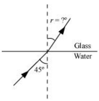
Angle of incidence,
Angle of refraction
From Snell’s law,
Hence, the angle of refraction at the water - glass interface is
Show Answer
Answer
Actual depth of the bulb in water,
Refractive index of water,
The given situation is shown in the following figure:
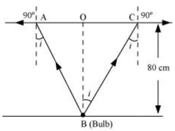
Where,
Since the bulb is a point source, the emergent light can be considered as a circle of radius,
Using Snell’ law, we can write the relation for the refractive index of water as:
Using the given figure, we have the relation:
Hence, the area of the surface of water through which the light from the bulb can emerge is approximately
Show Answer
Answer
Angle of minimum deviation,
Angle of the prism,
Refractive index of water,
Refractive index of the material of the prism
The angle of deviation is related to refractive index
Hence, the refractive index of the material of the prism is 1.532 .
Since the prism is placed in water, let
The refractive index of glass with respect to water is given by the relation:
Hence, the new minimum angle of deviation is
Show Answer
Answer
Refractive index of glass,
Focal length of the double-convex lens,
Radius of curvature of one face of the lens
Radius of curvature of the other face of the lens
Radius of curvature of the double-convex lens
The value of
Hence, the radius of curvature of the double-convex lens is
Show Answer
Answer
In the given situation, the object is virtual and the image formed is real.
Object distance,
Focal length of the convex lens,
Image distance
According to the lens formula, we have the relation:
Hence, the image is formed
Focal length of the concave lens,
Image distance
According to the lens formula, we have the relation:
Hence, the image is formed
Show Answer
Answer
Size of the object,
Object distance,
Focal length of the concave lens,
Image distance
According to the lens formula, we have the relation:
Hence, the image is formed on the other side of the lens,
The magnification of the image is given as:
Hence, the height of the image is
If the object is moved further away from the lens, then the virtual image will move toward the focus of the lens, but not beyond it. The size of the image will decrease with the increase in the object distance.
Show Answer
Answer
Focal length of the convex lens,
Focal length of the concave lens,
Focal length of the system of lenses
The equivalent focal length of a system of two lenses in contact is given as:
Hence, the focal length of the combination of lenses is
Show Answer
Answer
Focal length of the objective lens,
Focal length of the eyepiece,
Distance between the objective lens and the eyepiece,
Least distance of distinct vision,
Object distance for the eyepiece
According to the lens formula, we have the relation:
Image distance for the objective lens,
Object distance for the objective lens
According to the lens formula, we have the relation:
Magnitude of the object distance,
The magnifying power of a compound microscope is given by the relation:
Hence, the magnifying power of the microscope is 20 .
The final image is formed at infinity.
Object distance for the eyepiece
According to the lens formula, we have the relation:
Image distance for the objective lens,
Object distance for the objective lens
According to the lens formula, we have the relation:
Magnitude of the object distance,
The magnifying power of a compound microscope is given by the relation:
Hence, the magnifying power of the microscope is 13.51 .
Show Answer
Answer
Focal length of the objective lens,
Focal length of the eyepiece,
Object distance for the objective lens,
Least distance of distant vision,
Image distance for the eyepiece,
Object distance for the eyepiece
Using the lens formula, we can obtain the value of
We can also obtain the value of the image distance for the objective lens
The distance between the objective lens and the eyepiece
The magnifying power of the microscope is calculated as:
Hence, the magnifying power of the microscope is 88 .
Show Answer
Answer
Focal length of the objective lens,
Focal length of the eyepiece,
The magnifying power of the telescope is given as:
The separation between the objective lens and the eyepiece is calculated as:
Hence, the magnifying power of the telescope is 24 and the separation between the objective lens and the eyepiece is
(b) If this telescope is used to view the moon, what is the diameter of the image of the moon formed by the objective lens? The diameter of the moon is
Show Answer
Answer
Focal length of the objective lens,
Focal length of the eyepiece,
The angular magnification of a telescope is given as:
Hence, the angular magnification of the given refracting telescope is 1500 .
Diameter of the moon,
Radius of the lunar orbit,
Let
The angle subtended by the diameter of the moon is equal to the angle subtended by the image.
Hence, the diameter of the moon’s image formed by the objective lens is
(a) an object placed between
(b) a convex mirror always produces a virtual image independent of the location of the object.
(c) the virtual image produced by a convex mirror is always diminished in size and is located between the focus and the pole.
(d) an object placed between the pole and focus of a concave mirror produces a virtual and enlarged image.
[Note: This exercise helps you deduce algebraically properties of images that one obtains from explicit ray diagrams.]
Show Answer
Answer
For a concave mirror, the focal length
When the object is placed on the left side of the mirror, the object distance
For image distance
The object lies between
Using equation (1), we get:
Therefore, the image lies beyond
For a convex mirror, the focal length
When the object is placed on the left side of the mirror, the object distance
For image distance
Using equation (2), we can conclude that:
Thus, the image is formed on the back side of the mirror.
Hence, a convex mirror always produces a virtual image, regardless of the object distance.
For a convex mirror, the focal length
When the object is placed on the left side of the mirror, the object distance
For image distance
But we have
Hence, the image formed is diminished and is located between the focus
For a concave mirror, the focal length
When the object is placed on the left side of the mirror, the object distance
It is placed between the focus
For image distance
The image is formed on the right side of the mirror. Hence, it is a virtual image.
For
Magnification,
Hence, the formed image is enlarged.
Show Answer
Answer
Actual depth of the pin,
Apparent dept of the pin
Refractive index of glass,
Ratio of actual depth to the apparent depth is equal to the refractive index of glass, i.e.
The distance at which the pin appears to be raised
For a small angle of incidence, this distance does not depend upon the location of the slab.

FIGURE 9.28 (b) What is the answer if there is no outer covering of the pipe?
Show Answer
Answer
Refractive index of the glass fibre,
Refractive index of the outer covering of the pipe,
Angle of incidence
Angle of refraction
Angle of incidence at the interface
The refractive index
For the critical angle, total internal reflection (TIR) takes place only when
Maximum angle of reflection,
Let,
The refractive index at the air - glass interface,
We have the relation for the maximum angles of incidence and reflection as:
Thus, all the rays incident at angles lying in the range
If the outer covering of the pipe is not present, then:
Refractive index of the outer pipe,
For the angle of incidence
Since
Show Answer
Answer
Distance between the object and the image,
Maximum focal length of the convex lens
For real images, the maximum focal length is given as:
Hence, for the required purpose, the maximum possible focal length of the convex lens is
Show Answer
Answer
Distance between the image (screen) and the object,
Distance between two locations of the convex lens,
Focal length of the lens
Focal length is related to
Therefore, the focal length of the convex lens is
(b) An object
Show Answer
Answer
Focal length of the convex lens,
Focal length of the concave lens,
Distance between the two lenses,
When the parallel beam of light is incident on the convex lens first:
According to the lens formula, we have:
Where,
The image will act as a virtual object for the concave lens.
Applying lens formula to the concave lens, we have:
Where,
The parallel incident beam appears to diverge from a point that is
from the centre of the combination of the two lenses.
(ii) When the parallel beam of light is incident, from the left, on the concave lens first:
According to the lens formula, we have:
Where,
The image will act as a real object for the convex lens.
Applying lens formula to the convex lens, we have:
Where,
Hence, the parallel incident beam appear to diverge from a point that is
The answer does depend on the side of the combination at which the parallel beam of light is incident. The notion of effective focal length does not seem to be useful for this combination.
Height of the image,
Object distance from the side of the convex lens,
According to the lens formula:
Where,
Magnification,
Hence, the magnification due to the convex lens is 3 .
The image formed by the convex lens acts as an object for the concave lens.
According to the lens formula:
Where,
Magnification,
Hence, the magnification due to the concave lens is
The magnification produced by the combination of the two lenses is calculated as:
The magnification of the combination is given as:
Where,
Hence, the height of the image is
Show Answer
Answer
The incident, refracted, and emergent rays associated with a glass prism
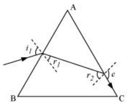
Angle of prism,
Refractive index of the prism,
According to Snell’s law, for face AC, we can have:
It is clear from the figure that angle
According to Snell’s law, we have the relation:
Hence, the angle of incidence is
(a) What is the magnification produced by the lens? How much is the area of each square in the virtual image?
(b) What is the angular magnification (magnifying power) of the lens?
(c) Is the magnification in (a) equal to the magnifying power in (b)? Explain.
Show Answer
Answer
Area of each square,
Object distance,
Focal length of a converging lens,
For image distance
Magnification,
Magnifying power of the lens
The magnification in (a) is not the same as the magnifying power in (b).
The magnification magnitude is
The two quantities will be equal when the image is formed at the near point
(b) What is the magnification in this case?
(c) Is the magnification equal to the magnifying power in this case? Explain.
Show Answer
Answer
The maximum possible magnification is obtained when the image is formed at the near point
Image distance,
Focal length,
Object distance
According to the lens formula, we have:
Hence, to view the squares distinctly, the lens should be kept
Magnification
Magnifying power
Since the image is formed at the near point
[Note: Exercises 9.22 to 9.24 will help you clearly understand the difference between magnification in absolute size and the angular magnification (or magnifying power) of an instrument.]
Show Answer
Answer
Area of the virtual image of each square,
Area of each square,
Hence, the linear magnification of the object can be calculated as:
But
Focal length of the magnifying glass,
According to the lens formula, we have the relation:
And
The virtual image is formed at a distance of
(a) The angle subtended at the eye by an object is equal to the angle subtended at the eye by the virtual image produced by a magnifying glass. In what sense then does a magnifying glass provide angular magnification?
(b) In viewing through a magnifying glass, one usually positions one’s eyes very close to the lens. Does angular magnification change if the eye is moved back?
(c) Magnifying power of a simple microscope is inversely proportional to the focal length of the lens. What then stops us from using a convex lens of smaller and smaller focal length and achieving greater and greater magnifying power?
(d) Why must both the objective and the eyepiece of a compound microscope have short focal lengths?
(e) When viewing through a compound microscope, our eyes should be positioned not on the eyepiece but a short distance away from it for best viewing. Why? How much should be that short distance between the eye and eyepiece?
Show Answer
Answer
(a)Though the image size is bigger than the object, the angular size of the image is equal to the angular size of the object. A magnifying glass helps one see the objects placed closer than the least distance of distinct vision (i.e.,
Yes, the angular magnification changes. When the distance between the eye and a magnifying glass is increased, the angular magnification decreases a little. This is because the angle subtended at the eye is slightly less than the angle subtended at the lens. Image distance does not have any effect on angular magnification.
The focal length of a convex lens cannot be decreased by a greater amount. This is because making lenses having very small focal lengths is not easy. Spherical and chromatic aberrations are produced by a convex lens having a very small focal length.
The angular magnification produced by the eyepiece of a compound microscope is
Where,
It can be inferred that if
The angular magnification of the objective lens of a compound microscope is given as
Where,
The magnification is large when
(e)When we place our eyes too close to the eyepiece of a compound microscope, we are unable to collect much refracted light. As a result, the field of view decreases substantially. Hence, the clarity of the image gets blurred.
The best position of the eye for viewing through a compound microscope is at the eyering attached to the eyepiece. The precise location of the eye depends on the separation between the objective lens and the eyepiece.
Show Answer
Answer
Focal length of the objective lens,
Focal length of the eyepiece,
Least distance of distinct vision,
Angular magnification of the compound microscope
Total magnifying power of the compound microscope,
The angular magnification of the eyepiece is given by the relation:
The angular magnification of the objective lens
We also have the relation:
Applying the lens formula for the objective lens:
The object should be placed
Applying the lens formula for the eyepiece:
Where,
Separation between the objective lens and the eyepiece
Therefore, the separation between the objective lens and the eyepiece should be
(a) the telescope is in normal adjustment (i.e., when the final image is at infinity)?
(b) the final image is formed at the least distance of distinct vision
9.28 (a) For the telescope described in Exercise 9.27 (a), what is the separation between the objective lens and the eyepiece?
(b) If this telescope is used to view a
(c) What is the height of the final image of the tower if it is formed at
9.29 A Cassegrain telescope uses two mirrors as shown in Fig. 9.26. Such a telescope is built with the mirrors
Show Answer
Answer
Focal length of the objective lens,
Focal length of the eyepiece,
In normal adjustment, the separation between the objective lens and the eyepiece
Height of the tower,
Distance of the tower (object) from the telescope,
The angle subtended by the tower at the telescope is given as:
The angle subtended by the image produced by the objective lens is given as:
Where,
Therefore, the objective lens forms a
Image is formed at a distance,
The magnification of the eyepiece is given by the relation:
Height of the final image
Hence, the height of the final image of the tower is

FIGURE 9.29
Show Answer
Answer
Angle of deflection,
Distance of the screen from the mirror,
The reflected rays get deflected by an amount twice the angle of deflection i.e.,
The displacement
Hence, the displacement of the reflected spot of light is

FIGURE 9.30
Show Answer
Answer
Focal length of the convex lens,
The liquid acts as a mirror. Focal length of the liquid
Focal length of the system (convex lens + liquid),
For a pair of optical systems placed in contact, the equivalent focal length is given as:
Let the refractive index of the lens be
Let
Radius of curvature of the liquid on the side of the plane mirror
Radius of curvature of the liquid on the side of the lens,
The value of
Hence, the refractive index of the liquid is 1.33 .


