Wave Optics
10.1 INTRODUCTION
In 1637 Descartes gave the corpuscular model of light and derived Snell’s law. It explained the laws of reflection and refraction of light at an interface. The corpuscular model predicted that if the ray of light (on refraction) bends towards the normal then the speed of light would be greater in the second medium. This corpuscular model of light was further developed by Isaac Newton in his famous book entitled OPTICKS and because of the tremendous popularity of this book, the corpuscular model is very often attributed to Newton.
In 1678, the Dutch physicist Christiaan Huygens put forward the wave theory of light - it is this wave model of light that we will discuss in this chapter. As we will see, the wave model could satisfactorily explain the phenomena of reflection and refraction; however, it predicted that on refraction if the wave bends towards the normal then the speed of light would be less in the second medium. This is in contradiction to the prediction made by using the corpuscular model of light. It was much later confirmed by experiments where it was shown that the speed of light in water is less than the speed in air confirming the prediction of the wave model; Foucault carried out this experiment in 1850.
The wave theory was not readily accepted primarily because of Newton’s authority and also because light could travel through vacuum
and it was felt that a wave would always require a medium to propagate from one point to the other. However, when Thomas Young performed his famous interference experiment in 1801, it was firmly established that light is indeed a wave phenomenon. The wavelength of visible light was measured and found to be extremely small; for example, the wavelength of yellow light is about
After the interference experiment of Young in 1801, for the next 40 years or so, many experiments were carried out involving the interference and diffraction of lightwaves; these experiments could only be satisfactorily explained by assuming a wave model of light. Thus, around the middle of the nineteenth century, the wave theory seemed to be very well established. The only major difficulty was that since it was thought that a wave required a medium for its propagation, how could light waves propagate through vacuum. This was explained when Maxwell put forward his famous electromagnetic theory of light. Maxwell had developed a set of equations describing the laws of electricity and magnetism and using these equations he derived what is known as the wave equation from which he predicted the existence of electromagnetic waves*. From the wave equation, Maxwell could calculate the speed of electromagnetic waves in free space and he found that the theoretical value was very close to the measured value of speed of light. From this, he propounded that light must be an electromagnetic wave. Thus, according to Maxwell, light waves are associated with changing electric and magnetic fields; changing electric field produces a time and space varying magnetic field and a changing magnetic field produces a time and space varying electric field. The changing electric and magnetic fields result in the propagation of electromagnetic waves (or light waves) even in vacuum.
In this chapter we will first discuss the original formulation of the Huygens principle and derive the laws of reflection and refraction. In Sections 10.4 and 10.5, we will discuss the phenomenon of interference which is based on the principle of superposition. In Section 10.6 we will discuss the phenomenon of diffraction which is based on HuygensFresnel principle. Finally in Section 10.7 we will discuss the phenomenon of polarisation which is based on the fact that the light waves are transverse electromagnetic waves.
10.2 HUYGENS PRINCIPLE
We would first define a wavefront: when we drop a small stone on a calm pool of water, waves spread out from the point of impact. Every point on the surface starts oscillating with time. At any instant, a photograph of the surface would show circular rings on which the disturbance is maximum. Clearly, all points on such a circle are oscillating in phase because they are at the same distance from the source. Such a locus of points, which oscillate in phase is called a wavefront; thus a wavefront is defined as a surface of constant phase. The speed with which the wavefront moves outwards from the source is called the speed of the wave. The energy of the wave travels in a direction perpendicular to the wavefront.
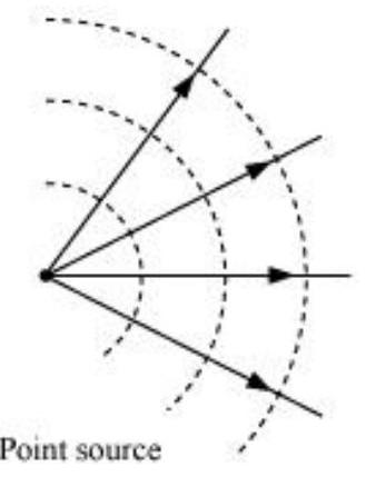
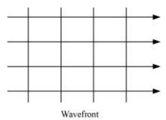
If we have a point source emitting waves uniformly in all directions, then the locus of points which have the same amplitude and vibrate in the same phase are spheres and we have what is known as a spherical wave as shown in Fig. 10.1(a). At a large distance from the source, a small portion of the sphere can be considered as a plane and we have what is known as a plane wave [Fig. 10.1(b)].
Now, if we know the shape of the wavefront at
of the wave. These wavelets emanating from the wavefront are usually referred to as secondary wavelets and if we draw a common tangent

FIGURE 10.1 (a) A diverging spherical wave emanating from a point source. The wavefronts are spherical.

FIGURE 10.1 (b) At a
large distance from the source, a small portion of the spherical wave can be approximated by a plane wave. to all these spheres, we obtain the new position of the wavefront at a later time.

FIGURE 10.2

FIGURE 10.3
Huygens geometrical construction for a plane wave propagating to the right.
The above model has one shortcoming: we also have a backwave which is shown as
In a similar manner, we can use Huygens principle to determine the shape of the wavefront for a plane wave propagating through a medium (Fig. 10.3).
10.3 REFRACTION AND REFLECTION OF PLANE WAVES USING HUYGENS PRINCIPLE
10.3.1 Refraction of a plane wave
We will now use Huygens principle to derive the laws of refraction. Let

FIGURE 10.4 A plane wave
In order to determine the shape of the refracted wavefront, we draw a sphere of radius
and
where
From the above equation, we get the important result that if
and
are known as the refractive indices of medium 1 and respectively. In terms of the refractive indices, Eq. (10.3) can be written as
This is the Snell’s law of refraction. Further, if
or
The above equation implies that when a wave gets refracted into a denser medium
10.3.2 Refraction at a rarer medium
We now consider refraction of a plane wave at a rarer medium, i.e.,
Thus, if

FIGURE 10.5 Refraction of a plane wave incident on a rarer medium for which
10.3.3 Reflection of a plane wave by a plane surface
We next consider a plane wave
In order to construct the reflected wavefront we draw a sphere of radius

FIGURE 10.6 Reflection of a plane wave
If we now consider the triangles
Once we have the laws of reflection and refraction, the behaviour of prisms, lenses, and mirrors can be understood. These phenomena were discussed in detail in Chapter 9 on the basis of rectilinear propagation of light. Here we just describe the behaviour of the wavefronts as they undergo reflection or refraction. In Fig. 10.7(a) we consider a plane wave passing through a thin prism. Clearly, since the speed of light waves is less in glass, the lower portion of the incoming wavefront (which travels through the greatest thickness of glass) will get delayed resulting in a tilt in the emerging wavefront as shown in the figure. In Fig. 10.7(b) we consider a plane wave incident on a thin convex lens; the central part of the incident plane wave traverses the thickest portion of the lens and is delayed the most. The emerging wavefront has a depression at the centre and therefore the wavefront becomes spherical and converges to the point F which is known as the focus. In Fig. 10.7(c) a plane wave is incident on a concave mirror and on reflection we have a spherical wave converging to the focal point
From the above discussion it follows that the total time taken from a point on the object to the corresponding point on the image is the same measured along any ray. For example, when a convex lens focusses light to form a real image, although the ray going through the centre traverses a shorter path, but because of the slower speed in glass, the time taken is the same as for rays travelling near the edge of the lens.

FIGURE 10.7 Refraction of a plane wave by (a) a thin prism, (b) a convex lens. (c) Reflection of a plane wave by a concave mirror.
Example 10.1
(a) When monochromatic light is incident on a surface separating two media, the reflected and refracted light both have the same frequency as the incident frequency. Explain why?
(b) When light travels from a rarer to a denser medium, the speed decreases. Does the reduction in speed imply a reduction in the energy carried by the light wave?
(c) In the wave picture of light, intensity of light is determined by the square of the amplitude of the wave. What determines the intensity of light in the photon picture of light.
Solution
(a) Reflection and refraction arise through interaction of incident light with the atomic constituents of matter. Atoms may be viewed as oscillators, which take up the frequency of the external agency (light) causing forced oscillations. The frequency of light emitted by a charged oscillator equals its frequency of oscillation. Thus, the frequency of scattered light equals the frequency of incident light.
(b) No. Energy carried by a wave depends on the amplitude of the wave, not on the speed of wave propagation.
(c) For a given frequency, intensity of light in the photon picture is determined by the number of photons crossing an unit area per unit time.

FIGURE 10.8 (a) Two needles oscillating in phase in water represent two coherent sources.
(b) The pattern of displacement of water molecules at an instant on the surface of water
showing nodal
10.4 COHERENT AND INCOHERENT ADDITION OF WAVES
In this section we will discuss the interference pattern produced by the superposition of two waves. You may recall that we had discussed the superposition principle in Chapter 14 of your Class XI textbook. Indeed the entire field of interference is based on the superposition principle according to which at a particular point in the medium, the resultant displacement produced by a number of waves is the vector sum of the displacements produced by each of the waves.
Consider two needles
Since the distances
Thus, if the displacement produced by the source
then, the displacement produced by the source
Thus, the resultant of displacement at
Since the intensity is proportional to the square of the amplitude, the resultant intensity will be given by
where
The waves emanating from
then the displacement produced by
where we have used the fact that a path difference of
We next consider a point R [Fig. 10.9(b)] for which
The waves emanating from
then the displacement produced by

FIGURE 10.9
(a) Constructive interference at a point
(b) Destructive interference at a point

FIGURE 10.10 Locus of points for which
To summarise: If we have two coherent sources
we will have constructive interference and the resultant intensity will be
we will have destructive interference and the resultant intensity will be zero. Now, for any other arbitrary point G (Fig. 10.10) let the phase difference between the two displacements be
then, the displacement produced by
and the resultant displacement will be given by
The amplitude of the resultant displacement is
If
Now if the two sources are coherent (i.e., if the two needles are going up and down regularly) then the phase difference
When the phase difference between the two vibrating sources changes rapidly with time, we say that the two sources are incoherent and when this happens the intensities just add up. This is indeed what happens when two separate light sources illuminate a wall.
10.5 INTERFERENCE OF LIGHT WAVES AND YOUNG’S EXPERIMENT
We will now discuss interference using light waves. If we use two sodium lamps illuminating two pinholes (Fig. 10.11) we will not observe any interference fringes. This is because of the fact that the light wave emitted from an ordinary source (like a sodium lamp) undergoes abrupt phase changes in times of the order of

phase relationship and would be incoherent, when this happens, as discussed in the previous section, the intensities on the screen will add up.
The British physicist Thomas Young used an ingenious technique to “lock” the phases of the waves
FIGURE 10.11 If two sodium lamps illuminate two pinholes
The spherical waves emanating from

We will have constructive interference resulting in a bright region when
On the other hand, we will have destructive interference resulting in a dark region when
Thus dark and bright bands appear on the screen, as shown in Fig. 10.13. Such bands are called fringes. Equations (10.13) and (10.14) show that dark and bright fringes are equally spaced.

FIGURE 10.13 Computer generated fringe pattern produced by two point source
Tata McGraw Hill Publishing Co. Ltd., New Delhi, 2000.)
10.6 DIFFRACTION
If we look clearly at the shadow cast by an opaque object, close to the region of geometrical shadow, there are alternate dark and bright regions just like in interference. This happens due to the phenomenon of diffraction. Diffraction is a general characteristic exhibited by all types of waves, be it sound waves, light waves, water waves or matter waves. Since the wavelength of light is much smaller than the dimensions of most obstacles; we do not encounter diffraction effects of light in everyday
observations. However, the finite resolution of our eye or of optical instruments such as telescopes or microscopes is limited due to the phenomenon of diffraction. Indeed the colours that you see when a CD is viewed is due to diffraction effects. We will now discuss the phenomenon of diffraction.
10.6.1 The single slit
In the discussion of Young’s experiment, we stated that a single narrow slit acts as a new source from which light spreads out. Even before Young, early experimenters - including Newton - had noticed that light spreads out from narrow holes and slits. It seems to turn around corners and enter regions where we would expect a shadow. These effects, known as diffraction, can only be properly understood using wave ideas. After all, you are hardly surprised to hear sound waves from someone talking around a corner!
When the double slit in Young’s experiment is replaced by a single narrow slit (illuminated by a monochromatic source), a broad pattern with a central bright region is seen. On both sides, there are alternate dark and bright regions, the intensity becoming weaker away from the centre (Fig. 10.15). To understand this, go to Fig. 10.14, which shows a parallel beam of light falling normally on a single slit LN of width
A straight line through M perpendicular

FIGURE 10.14 The geometry of path differences for diffraction by a single slit. to the slit plane meets the screen at
The basic idea is to divide the slit into much smaller parts, and add their contributions at
It is observed that the intensity has a central maximum at
The photograph and intensity pattern corresponding to it is shown in Fig. 10.15.
There has been prolonged discussion about difference between intereference and diffraction among

FIGURE 10.15 Intensity distribution and photograph of fringes due to diffraction at single slit. scientists since the discovery of these phenomena. In this context, it is interesting to note what Richard Feynman* has said in his famous Feynman Lectures on Physics:
No one has ever been able to define the difference between interference and diffraction satisfactorily. It is just a question of usage, and there is no specific, important physical difference between them. The best we can do is, roughly speaking, is to say that when there are only a few sources, say two interfering sources, then the result is usually called interference, but if there is a large number of them, it seems that the word diffraction is more often used.
In the double-slit experiment, we must note that the pattern on the screen is actually a superposition of single-slit diffraction from each slit or hole, and the double-slit interference pattern.
10.6.2 Seeing the single slit diffraction pattern
It is surprisingly easy to see the single-slit diffraction pattern for oneself. The equipment needed can be found in most homes - two razor blades and one clear glass electric bulb preferably with a straight filament. One has to hold the two blades so that the edges are parallel and have a narrow slit in between. This is easily done with the thumb and forefingers (Fig. 10.16).
Keep the slit parallel to the filament, right in front of the eye. Use spectacles if you normally do. With slight adjustment of the width of the slit and the parallelism of the edges, the pattern should be seen with its bright and dark bands. Since the position of all the bands (except the central one) depends on wavelength, they will show some colours. Using a filter for red or blue will make the fringes clearer. With both filters available, the wider fringes for red compared to blue can be seen.
In this experiment, the filament plays the role of the first slit
With some effort, one can cut a double slit in an aluminium foil with a blade. The bulb filament can be viewed as before to repeat Young’s experiment. In daytime, there is another suitable bright source subtending a small angle at the eye. This is the reflection of the Sun in any shiny convex surface (e.g., a cycle bell). Do not try direct sunlight - it can damage the eye and will not give fringes anyway as the Sun subtends an angle of
In interference and diffraction, light energy is redistributed. If it reduces in one region, producing a dark fringe, it increases in another region, producing a bright fringe. There is no gain or loss of energy, which is consistent with the principle of conservation of energy.[^0]
10.7 POLARISATION
Consider holding a long string that is held horizontally, the other end of which is assumed to be fixed. If we move the end of the string up and down in a periodic manner, we will generate a wave propagating in the

FIGURE 10.17 (a) The curves represent the displacement of a string at
in the
where
represents the wavelength associated with the wave. We had discussed propagation of such waves in Chapter 14 of Class XI textbook. Since the displacement (which is along the
In a similar manner we can consider the vibration of the string in the
It should be mentioned that the linearly polarised waves [described by Eqs. (10.15) and (10.17)] are all transverse waves; i.e., the displacement of each point of the string is always at right angles to the direction of propagation of the wave. Finally, if the plane of vibration of the string is changed randomly in very short intervals of time, then we have what is known as an unpolarised wave. Thus, for an unpolarised wave the displacement will be randomly changing with time though it will always be perpendicular to the direction of propagation.
Light waves are transverse in nature; i.e., the electric field associated with a propagating light wave is always at right angles to the direction of propagation of the wave. This can be easily demonstrated using a simple polaroid. You must have seen thin plastic like sheets, which are called polaroids. A polaroid consists of long chain molecules aligned in a particular direction. The electric vectors (associated with the propagating light wave) along the direction of the aligned molecules get absorbed. Thus, if an unpolarised light wave is incident on such a polaroid then the light wave will get linearly polarised with the electric vector oscillating along a direction perpendicular to the aligned molecules; this direction is known as the pass-axis of the polaroid.
Thus, if the light from an ordinary source (like a sodium lamp) passes through a polaroid sheet
The experiment at figure 10.18 can be easily understood by assuming that light passing through the polaroid
where

FIGURE 10.18 (a) Passage of light through two polaroids
The double arrows show the oscillations of the electric vector.
intensity coming out of a single polaroid is half of the incident intensity. By putting a second polaroid, the intensity can be further controlled from
Polaroids can be used to control the intensity, in sunglasses, windowpanes, etc. Polaroids are also used in photographic cameras and 3D movie cameras.
Example 10.2 Discuss the intensity of transmitted light when a polaroid sheet is rotated between two crossed polaroids?
Solution Let
where
Therefore, the transmitted intensity will be maximum when
SUMMARY
1. Huygens’ principle tells us that each point on a wavefront is a source of secondary waves, which add up to give the wavefront at a later time.
2. Huygens’ construction tells us that the new wavefront is the forward envelope of the secondary waves. When the speed of light is independent of direction, the secondary waves are spherical. The rays are then perpendicular to both the wavefronts and the time of travel is the same measured along any ray. This principle leads to the well known laws of reflection and refraction.
3. The principle of superposition of waves applies whenever two or more sources of light illuminate the same point. When we consider the intensity of light due to these sources at the given point, there is an interference term in addition to the sum of the individual intensities. But this term is important only if it has a non-zero average, which occurs only if the sources have the same frequency and a stable phase difference.
4. Young’s double slit of separation d gives equally spaced interference fringes.
5. A single slit of width
6. Natural light, e.g., from the sun is unpolarised. This means the electric vector takes all possible directions in the transverse plane, rapidly and randomly, during a measurement. A polaroid transmits only one component (parallel to a special axis). The resulting light is called linearly polarised or plane polarised. When this kind of light is viewed through a second polaroid whose axis turns through
POINTS TO PONDER
1. Waves from a point source spread out in all directions, while light was seen to travel along narrow rays. It required the insight and experiment of Huygens, Young and Fresnel to understand how a wave theory could explain all aspects of the behaviour of light.
2. The crucial new feature of waves is interference of amplitudes from different sources which can be both constructive and destructive, as shown in Young’s experiment.
3. Diffraction phenomena define the limits of ray optics. The limit of the ability of microscopes and telescopes to distinguish very close objects is set by the wavelength of light.
4. Most interference and diffraction effects exist even for longitudinal waves like sound in air. But polarisation phenomena are special to transverse waves like light waves.
EXERCISES
10.1 Monochromatic light of wavelength
Show Answer
Answer
Let
Where,
For monochromatic light waves,
Phase difference
Since path difference
Phase difference,
Given,
When path difference
Phase difference,
Hence, resultant intensity,
Using equation (1), we can write:
Hence, the intensity of light at a point where the path difference is
(a) Light diverging from a point source.
(b) Light emerging out of a convex lens when a point source is placed at its focus.
(c) The portion of the wavefront of light from a distant star intercepted by the Earth.
Show Answer
Answer
The shape of the wavefront in case of a light diverging from a point source is spherical. The wavefront emanating from a point source is shown in the given figure.
The shape of the wavefront in case of a light emerging out of a convex lens when a point source is placed at its focus is a parallel grid. This is shown in the given figure.
The portion of the wavefront of light from a distant star intercepted by the Earth is a plane.
(b) Is the speed of light in glass independent of the colour of light? If not, which of the two colours red and violet travels slower in a glass prism?
Show Answer
Answer
Refractive index of glass,
Speed of light,
Speed of light in glass is given by the relation,
Hence, the speed of light in glass is
The speed of light in glass is not independent of the colour of light.
The refractive index of a violet component of white light is greater than the refractive index of a red component. Hence, the speed of violet light is less than the speed of red light in glass. Hence, violet light travels slower than red light in a glass prism.
Show Answer
Answer
Distance between the slits,
Distance between the slits and the screen,
Distance between the central fringe and the fourth
In case of a constructive interference, we have the relation for the distance between the two fringes as:
Where,
Hence, the wavelength of the light is
Show Answer
Answer
Let
Where,
For monochromatic light waves,
Phase difference
Since path difference
Phase difference,
Given,
When path difference
Phase difference,
Hence, resultant intensity,
Using equation (1), we can write:
Hence, the intensity of light at a point where the path difference is
(a) Find the distance of the third bright fringe on the screen from the central maximum for wavelength
(b) What is the least distance from the central maximum where the bright fringes due to both the wavelengths coincide?
Show Answer
Answer
Wavelength of the light beam,
Wavelength of another light beam,
Distance of the slits from the screen
Distance between the two slits
Distance of the
For third bright fringe,
Let the
Hence, the least distance from the central maximum can be obtained by the relation:
Note: The value of


