Unit-20 Communication Systems
Learning Objectives
After going through this unit, you will be able to understand, appreciate and apply the following concepts:
-
Concept of communication system.
-
Propagation of em-waves.
-
Different modes of (wireless) propagation of em-waves-ground wave, sky wave and space wave propagation.
-
Basic idea of modulation.
-
Need for modulation.
-
Different types of modulation-AM, FM and PM.
-
Advantages and disadvantages of FM over AM.
CONCEPT MAP
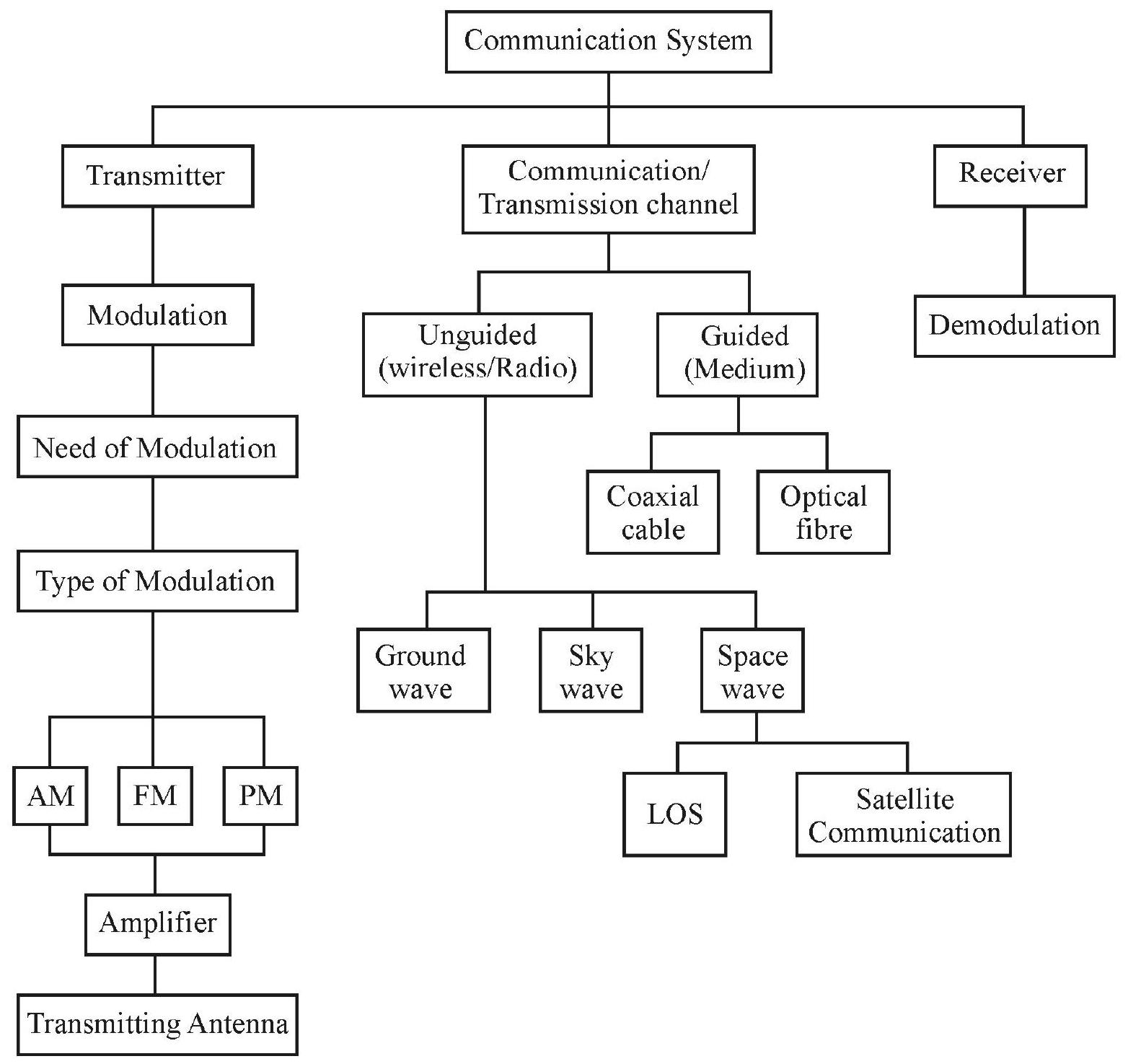
Communication System
Communication is the process of transmission of information from one point and it reception at another point. The set up used to achieve this goal, is termed as ‘communication system’. The purpose of a communication system, therefore, is to transmit information from a source, located at one place, to a receiver, located at another place.
Elements of a Communication System
A communication system consists of three basic parts (i) transmitter (ii) communication channel and (iii) reciever. The block diagram given below depicts the general form of a communication system.
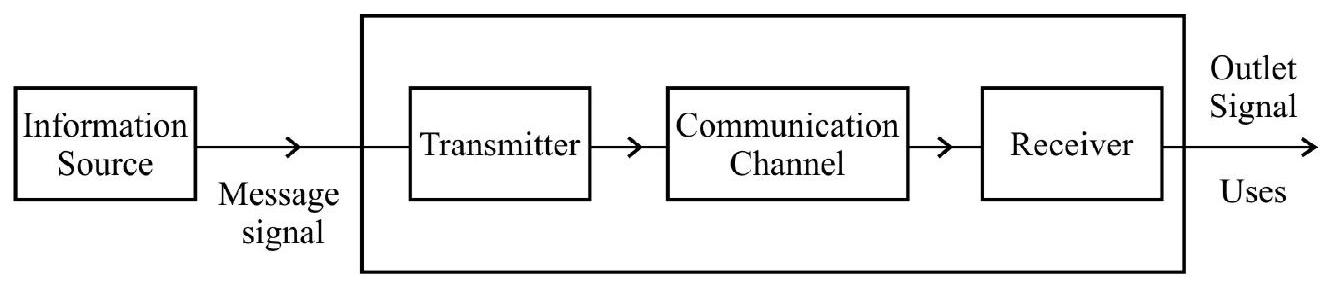
Fig. 1: Communication System
In a communication system, the transmitter transmits the message signal. The purpose of the transmitter is to convert the message signal, produced by the source of information, into a form suitable for transmission through the relevant communication channel. This modification is often achieved by means of a process known as ‘modulation’.
The communication channel carriers the modulated wave, form, from the transmitter to the receiver. This ‘channel’ can be a transmission line (as in telephony), an optical fibre (as in optical communication) or merely ‘free space’ in which the signal is radiated as an electromagnetic wave (wireless communication).
The main purpose of a receiver is to reconstruct the original message from the ‘signal received by it, after propagation through the channel. This is accomplished by using a process known as ‘demodulation’; this process is the reverse of the ‘modulation’ process, used in the transmitter.
Modes of Communication
There are two basic modes of communication: ‘point to point and ‘broadcast mode.
In the ‘point to point’ communication mode, communication takes place over a link between a single transmitter and a receive. ‘Telephony’ is the most familiar example of this mode of communication. In contrast, in the broadcast mode, there are a large number of receivers, corresponding to a single transmitter. Radio and television are two of the well known examples of this mode of communication.
Basic Terminology used in Communication System
We now familiarize ourselves with the basic terms used in communication systems.
1. Transducer: This is any device which converts one form of energy into another form. An electrical transducer may be defined as a device that converts the variations in some physical variable (pressure, displacement, force, temperature) into corresponding variations in an electrical signal given out at its output. For example microphone and loudspeakers act as transducers. They convert sound signals into electrical signal and vice-versa.
2. Message Signal: It is a time varying electrical signal, generated from some original signal, using an appropriate transducer. These signals can be analogue or digital in nature.
3. Attenuation: The loss of strength (or energy) of a signal, while propagating through a medium, is known as attenuation.
4. Range: It is the largest distance between source and a distination, upto which the transmitted signal can be received with sufficient strength.
5. Bandwidth: Bandwidth refers to the frequency range over which the equipment, of a channel, operates. It may also be viewed as (i) the position of the (e.m.) spectrum occupied by the signal, or (ii) as the difference of the highest frequency to the lowest frequency, within which transmission is taking place.
6. Repeater: A ‘repeater’ is the combination of a receiver and a transmitter. A repeater picks up the signal from the transmitter, amplifies it and retransmits it to the receiver. Repeaters are used to extend the range of a communication system. A communication satellite is essentially a repeater station in a space.
Bandwidth of a Signal
In a communication system, the message signal can be voice, music, picture or computer data. All of these ‘signals’, have ‘different ranges of frequencies’. For example speech signals require a bandwidth of 2800
Some Important Wireless Communication
| Nature of Service/Broadcast | Frequency Band |
|---|---|
| FM Radio | |
| VHF TV | |
| UHF TV | |
| Cellular Mobile Phone | |
Bandwidth of Transmission Medium
The commonly used transmission medium (communication channel) are wireless (radio communication) free space, coaxial cables and fibre optic cables. Coaxial cables are widely used ‘wire based medium’, which offers a bandwidth of approximately
Propagation of Electromagnetic Waves
In communication using radio waves, an antenna, at the transmitter end, radiates, the em-waves, which propagate through free space and reach the receiving antenna at the other end. An electromagnetic wave (em-wave), may be divided into various parts. The part, which propagates along the surface of earth is called surface wave (ground wave propagation). The remainder part moves towards the ionosphere and gets reflected by this ionosphere. Such type of propagation is called sky wave. Sky wave propagation can takes place for frequency up to about
Ground Wave
This mode of propagation is also called surface wave propagation as the wave glides over the surface of the earth. A wave induces current in the ground over which it passes; it is attenuated as a result of absorption of energy by the earth. The attenuation of surface wave increases very rapidly with increases in frequency. Hence this mode of propagation is limited to freqeuncy as up to few MHz.
Sky Wave
In the frequency range, from few
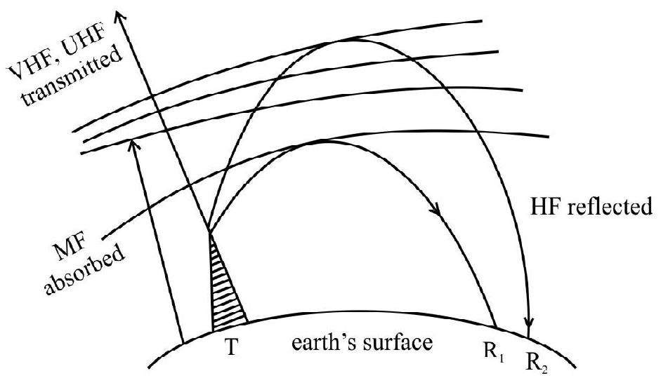
Fig. 2
Using multiple loops, in which the wave is reflected between the ionosphere and earth’s surface several times the propagation range can be increased.
Space Wave
A space wave propagates along a straight line; from the transmitting antenna to the receiving antenna. Space waves are used for line of sight (LOS) communication as well as satellite communication. At frequencies above
The distance,
We have,
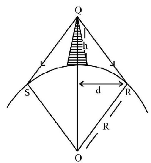
Fig. 3
Here
If the signal is to be received beyond the horizon then the receiving anteena must be high enough to intercept the ’line of sight’ waves.
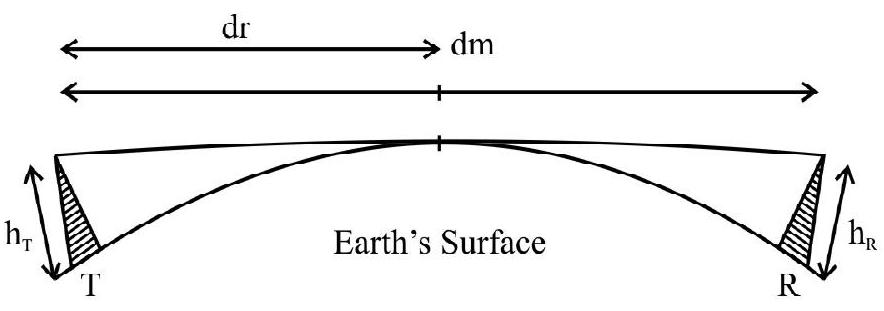
Fig. 4
The maximum ’line of sight’ distance,
An Interesting Feature of ‘Space Wave Propagation’
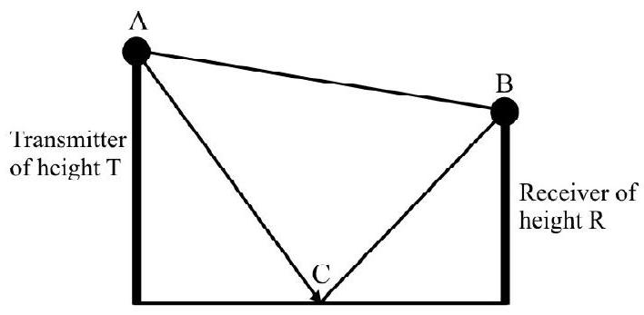
The propagation of e.m. waves, from the transmitter to the receiver, via space wave propagation, can take place in two ways:
(i) direct ’line of sight’ propagation from the transmitter to the receiver.
(ii) transmission from the transmitter towards the earth’s surface; reflection from the earth’s surface and receiving of the reflected waves by the receiver.
The two waves, at the reveiver, will in general, arrive with a certain phase difference between them. We can easily calculate this phase difference and see its affect on the ‘resultant field strength’ received at the receiver, under the assumption that the reflecting point, on the earth, is mid-way between the transmitter and receiver. Let a transmitter, of height
We than have
Direct path
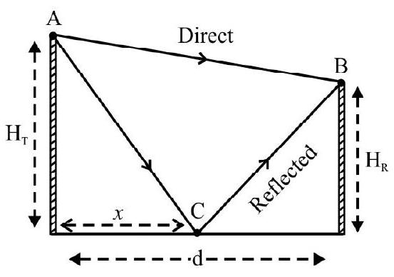
Fig. 5
(If
The reflected wave’s path
For simplification, we may take
We than have,
Reflected wave’s path
The total phase difference, however, will have an additional contribution of
The resultant field strength, at the receiver, can now be estimated. For simplification, we can take the individual field strengths, of the two waves arriving at the receiver, to be identical (say E’ each). We then have, in this special case,
Resultant field strength
Example-1:
A TV tower has a height of
Show Answer
Solution:
The radius of the region, covered by TV broadcast, in given by
The area of region covered will be
Example-2:
Which of the following frequencies, will be suitable for ‘beyond the horizon’ communication using sky wves?
(1)
(2)
(3)
(4)
Show Answer
Solution:
Example-3:
Which means of propagation is used for frequencies in the UHF (Ultra High Frequencies) range?
Show Answer
Solution:
Space wave propagation; either line of sight communication or satellite communication.
Modulation
For reasons listed below, the original low frequency message/information signal cannot be directly transmitted (as e.m. waves) over long distances. Therefore, at the transmitter end, such a low frequency message signal is superimposed on a high frequency wave, which acts as a ‘carrier’ of the information. This process is knowns as modulation.
Necessity of Modulation
Modulation is necessary because of the following reasons:
1. Size of Antenna or Areial: The antenna should have a size compaable to the wavelength of signal (at least
2. Effective Power Radiated by an Antenna: The power, radiated by an antenna of effective length ’
3. The use of high frequency (carrier) waves, ‘used’ during modulation, also helps to avoid mixing up of signals from different transmitters. This aim is achieved by alooting a (distance, non over-lapping) band of frequencies to each message signal during its transmissions.
From, the above discussion we conclude that there is a need for ’translating’ the original low frequency message signals into high frequency signals, before transmisstion. This transformation must be done in a way such that the ’translated’ signal still possesses the information contrained in the original signal. The high frequency wave, we use for this purpose, is known as the carrier wave.
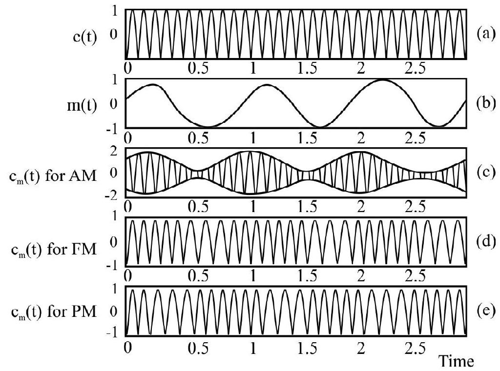
Fig. 6: Modulation of carrier wave
(a) a (b) a modulating signal
(c) amplitude modulation (d) modulation and
(e) phase modulation
During the process of modulation, any of the three parameters: ‘amplitude’, ‘frequency’ or ‘phase’, of the carrier wave, is controlled by the amplitude of the original message or information signal. This results in three types of modulation.
(i) Amplitude modulation (AM)
(ii) Frequency modulation (FM)
(iii) Phase modulation (PM)
These three types of modulation have been shown in the figure (6) given above.
Amplitude Modulation (AM)
In amplitude modulation the amplitude of the carrier
Let
Then amplitude modulated signal is given by
Here
The difference
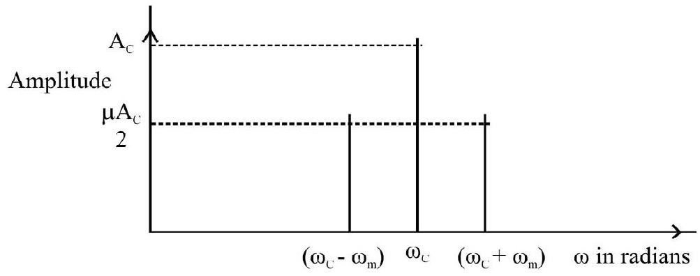
Fig. 7: A plot of amplitude versus
It is important to ensure that the broadcast frequencies (carrier waves) are sufficiently spaced out so that sidebands do not overlap. Different stations can then operate without interfering with each other.
Power Distribution between the (Original) ‘Carrier Wave’ and the ‘Side Bands’ in an Amplitude Modulated (Carrier) Wave
When a carrier wave
is amplitude modulated by a message signal
the resulting AM carrier wave
can be rewritten as
where
The AM carrier wave, therefore, has its power distributed between the original carrier wave and the two side bands accompyaning it. Their relative ‘shares’ depend on the value of
We have
Power of the original carrier wave
and power of each of the sideband waves
Here
And total power
Example-4:
A message signale of frequency
Show Answer
Solution:
(a) Modulation index
(b) THe side bands are at
Frequency Modulation (FM)
In this type of modulcation, the frequency of the carrier wave is varied in accordance with the amplitude of the modulating / information signal, this is shown in Figure 6(b).
Advantage of FM over AM
1. The FM signals has a larger bandwidth. Therefore, to accomodate more FM signals, on a particular frequency spectrum, without adjacent channel interference, higher carrier frequencies are used.
2. In FM signals, the intelligence is in the form of frequency variations. Hence the noise generated by atmospheric or man made electric discharge, does not affect the intelligence. Hence FM leads to less noisy transmission and reception.
3. Reproduction of the signal, at the receiver end, is of much better quality. FM is therefore, better for transmisstion of music.
Phase Modulation (PM)
The modulated wave follows the phase of the modulating / information signals as shown in Fig. 6 (c)
Production of Amplitude Modulated Wave
Amplitude modulation can be produced by a variety of methods. A simple method is shown in the block diagram of Fig. 8.
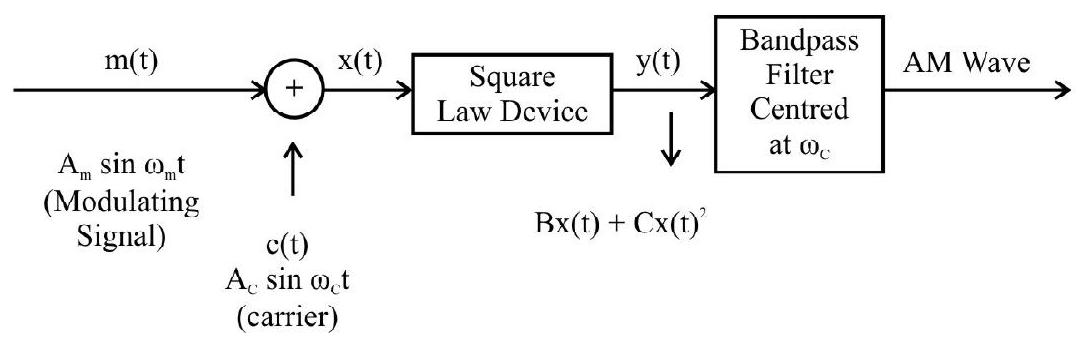
Fig. 8: Block diagram of a simple modulator for obtaining an AM signal
It is usual to have a ‘power amplifier’ for providing the necessary power to the output of an ‘amplitude modulator’. The output of the power amplifier, is fed into the ’transmitting antenna’ whose size is appropriate for good transmission.
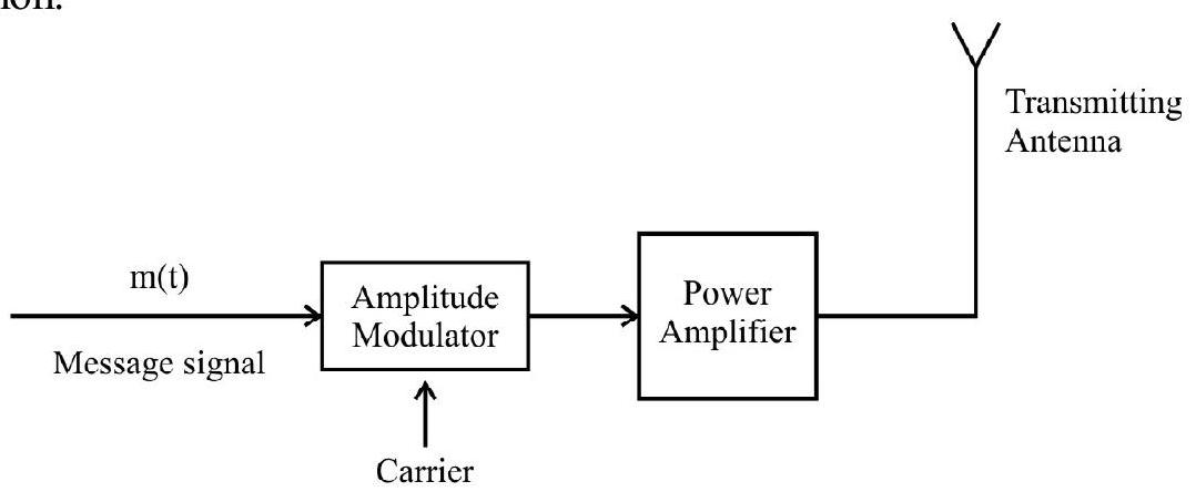
Fig. 9: Block diagram of a transmitler
Detection of Amplitude Modulated Wave
The amplitude modulated signal, when received by the receiving antenna, is made to go throgh the different stages, shown is the block diagram given below.
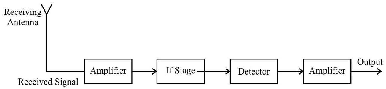
Fig. 10: Block diagram of a receiver
The signal received, is first amplified by using an appropriate amplifier. This is necessary to compensate for the energy lost during transmission. The IF (intermediate frequency) stage changes the (high) carrier frequency to a lower frequency. This helps in further processing of the signal. The detector receives the output of the IF stage and ‘separates out’ the ‘message signal’ from it. Another amplifier then amplifies this ‘message signal’ (received from the detector) before it is received as the output.
Detection
The (amplifier) modulated carrier wave has frequencies
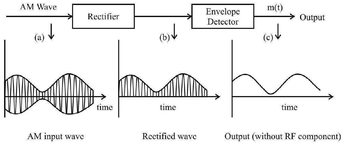
Fig. 11: Block diagram of a detector for AM signal
As shown here, the rectitier converts the Alvi wave into the torm shown. I he ’envelope detector’ then ’extracts’ the ’envelope’ of the rectified signal; this is the original message signal. [We use suitable circuits (like to RC circuit) to work as ’envelope detector’].
PROBLEMS FOR PRACTICE
1. What is the coverage range of television transmitting station if the height of transmitting atenna is
Show Answer
[Answer:2. A transmitting antenna of height
Show Answer
[Answer:3. For an amplitude modulated wave, the maximum amplitude is found to be
Show Answer
[Answer:4. A TV tower has a height of
Show Answer
[Answer: 6]5. When the modulating frequency in frequency modulating system is
Show Answer
[Answer: 160]6. What should be the length of dipole antenna for a carrier wave of frequency
Show Answer
[Answer:7. An AM wave is represented by
(i) amplitude and frequency of carrier.
(ii) frequency of the modulating signal.
(iii) modulation index.
(iv) maximum and minimum amplitude of the AM wave.
Show Answer
[Answer: (i)8. An audio signal of amplitude one half the carrier amplitude is employed in amplitude modulation. What is the modulation index?
Show Answer
[Answer:9. If the whole earth is to be connected by LOS communication using space waves (no restriction to antenna size or tower height), what is the minimum number of antennas required? Calculate the tower height of these anteenas in terms of earth’s surface?
Show Answer
[Answer: 6 antennas of height equal to radius of earth]10. Calculate the percentage increase in the signal reception, if the height of TV tower is increased by
Show Answer
[Answer:11. An AM wave is modulated by
Show Answer
[Answer:12. A sinusoidal carrier voltage of frequency
Show Answer
[Answer:13. For skywave propagation of a
Show Answer
[Answer:14. For an amplitude modulated wave, the maximum amplitude is found to be
Show Answer
[Answer:15. In short wave communication waves, which frequency will be reflected back by the ionospheric layer having electron density
Show Answer
[Answer:Question Bank
Key Learning Points
1. Electronic communication is the act of transmission of information. Every communication system has three essential features, transmitter, medium / channel and receiver.
2. There are two basic modes of communication point to point and broadcast.
3. Information converted in electrical form and suitable for transmission is called a signal. Two important forms of communication system are Analog and digital. The information to be transmitted is generally in continuous waveform for Analog while for the digital it has only discrete or quantised levels.
4. Every message signal occupies a range of frequencies. The bandwidth refers to the frequency range over the spectrum occupied by the signal.
5. Most of the signals are in audio form, which cannot be transmitted over a long distance becuase:
(i) the antenna or aerial should have a size comparable to the wavelength of signal.
(ii) power radiated
(iii) low frequency signals transmitted as such will get mixed up and there is no way to distinguish between them.
Hence to transmit audio frequency signals, we use a high frequency signal called the carrier wave.
6. At transmitter, information contained in the low frequency message signal is superimposed on high frequency wave, which act as a carrier of the information. This process is known as modulation.
7. In modulation, some characterstics of the carrier signal like amplitude frequency or phase varies in accordance with the modulation or message signal. Correspondingly, they are called Amplitude Modulated (AM), Freqeuncy Modulated (FM) or Phase Modulated (PM) waves.
8. For transmisstion over long distances, signals are radiated into sapce using devices called antennas. The radiated signals propagate as electromagnetic waves and the mode of propagation is influenced by the presence of the earth and its atmosphere.
9. The radio waves which travel through atmosphere following the surface of earth are known as ground waves or surface waves. The ground wave propagation becomes weaker with increase in frequency. Hence ground wave propagation is suitable for low and medium frequency i.e. upto 20 MHz only.
10. In the frequency range from
11. Space waves are radiowaves of very high frequency (between
12. The range of communication of space wave propagation can be increased by increasing the heights of transmitting and receiving antenna.
13. If
For T.V. signal, area covered
Population covered
If receiving antenna is at a height
14. The satellite communication is a mode of communication of signal between transmitter and receiver through satellite. A communication satellite is a space craft, provided with microwave receiver and transmitter. It is placed in a geostationary orbit. The height
where
15. The AM carrier wave has, in addition to its own frequency
16. If
where
17. Amplitude modulated wave
18. AM signal cannot be transmitted as such. The modulator is to be followed by a power amplifier which provides the necessary power and then the modulated signal is fed to an antenna of appropriate size for radiation.
19. AM detection, which is the process of recovering the modulating signal from an AM waveform; is carried out using a rectifier and envelope detector.
20. For detection of amplitude modulated wave, the essential condition is
where
Average
Message signal
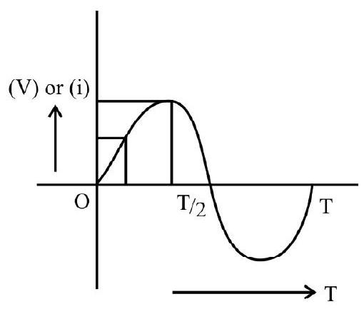
1. An audio message signal is a piece of information, which at a particular time,
(1) has only single value
(2) can have two values
(3) can hve a single value, or two values, depending on the time instant
(4) must have multiple values
Show Answer
Correct answer: (1)
Solution:
Audio signal, at a particular time, have only a single value, as their variation with time, is (usually) basically of the form shown here.
Average
Basic Elements of a Communication System
2. The ‘information source’, whose ‘message signal’ needs to be transmitted is (i) a picture (ii) a (audio) musical composition and (iii) a ‘pressure variation’. The transducers, likely to be used in the three cases, would be (respectively):
(1) based on photoelectric effect, based on piezoelectric effect and a microphone.
(2) based on piezoelectric effect, microphone and based on photoelectric effect.
(3) based on photoelectric effect; a microphone and based on piezoelectric effect.
(4) based on magneto-restriction effect; a microphone and based on photoelectric effect.
Show Answer
Correct answer: (3)
Solution:
A transducer is (usually) a device / setup that converts variations in a givn physical variable into their corresponding electrical variations. It thus ‘readies’ the message signal for transmission over large distances. For ‘picture’ (variations in light intensity) the relevant transducer is based on the ‘photoelectric effect’. For audio musical compositions (variations in sound intensity) the relevant transducer is the microphone. For pressure variation relevant transducer is based on the phenomenon of ‘piezo electric effect’.
Easy
Devices used in Communication System
3. The role of the satellites, in ’line of sight’ communication mode, can be regarded as similar to the role of a
(1) Transducer
(2) Transmitter
(3) Receiver
(4) Repeater
Show Answer
Correct answer: (4)
Solution:
The satellites, used for communication purposes, receive signals (from a transmitting station on the earth), amplify it and retransmit it (generally at a different carrier frequency) back towards the receiving stations on the earth. The role is, therefore, similar to that of a repeater. The repeater also picks up the signal from the transmitter, and retransmits it to the receiver, after amplifying it and (sometimes) changing its carrier frequency.
Easy
Space and Sky Wave Propagation
4. In the trosophere,
(1) Density of air molecules increases with increase in the altitude; and temperature decreases with increase in the altitude.
(2) Density of air molecules decreases with increases in the altitude; and temperature increases with increase in the altitutde.
(3) Density of air molecules and temperature, both increase with increase in the altitude.
(4) Density of air molecules and temperature, both decreases with increase in the altitude.
Show Answer
Correct answer: (4)
Solution:
The density of air molecules, as well as temperature of the air, have lower values at higher altitudes.
Easy
Space and Sky Wave Propagation
5. The atmospheric region which acts as ‘radio mirror’ is
(1) Troposphere
(2) Stratosphere
(3) Ionosphere
(4) Both troposphere and stratosphere
Show Answer
Correct answer: (3)
Solution:
Ionosphere (having a lot of air molecules ionised) reflects the radio waves back to the earth’s surface).
Easy
Space and Sky Wave Propagation
6. Thickest layer of the ionosphere is
(1) D layer
(2) E layer
(3) F1 layer
(4) F2 layer
Show Answer
Correct answer: (4)
Solution:
The approximate height of the four layers is as follows.
D layer
E layer
F1 layer -
F2 layer
Easy
Space and Sky Wave Propagation
7. Locus of points at which direct rays from the antenna are tangential to the earth surface is called as,
(1) Critical circle
(2) Radio horizon
(3) Skip distance
(4) Verticalheight
Show Answer
Correct answer: (2)
Solution:
The radio horizon is a measure of the distance between the transmitter and the receiver, when the receiver is receving the ’line of sight’ rays from the transmitter.
Easy
Space and Sky Wave Propagation
8. The atmospheric layer which reflects low frequency waves and absorbs medium frequency waves is,
(1) Troposphere
(2) D layer of the ionosphere
(3) E layer of the ionosphere
(4) F1 layer of the ionosphere
Show Answer
Correct answer: (2)
Solution:
It is the D layer, of the ionosphere which reflects low frequency waves and absorbs medium frequency waves.
Average
Propagation of EM Waves
9. The (usual) modes of propagation of EM waves, having a frequency.
(i) less than a few
(ii) from a few MHz to (30-40)
(iii) above
are respectively,
(1) Ground waves, space waves, sky waves
(2) Ground waves, sky waves, space waves
(3) Sky waves, space waves, ground waves
(4) Space waves, ground waves, sky waves
Show Answer
Correct answer: (2)
Solution:
In the ground wave mode of propagation the wave glides over the surface of the earth. This mode can be used only for frequencies less than a few MHz.
The sky wave uses the ionospheric reflection of radio waves; the ionospere does not reflect back waves of frequencies more than
The space wave mode of propagation is used for line sight communication and satellite communication is done primarily through this mode only.
Average
Propagation of EM Waves
10. With increase in frequency of the EM waves, to be transmitted via ground wave propagation, there is
(1) an increase in attenuation, but no change in the range of coverage
(2) a decrease in attenuation, but no change in the range of coverage
(3) an increase in attenuation, there is also a change in range of coverage
(4) a decrease in attenuation, there is also a change in the range of coverage
Show Answer
Correct answer: (3)
Solution:
In ground wave propagation, the attenuation of surface waves increases (very rapidly) with increase in frequency. The range of coverage also depends on the frequency of the transmitted EM Wave.
Average
Propagation of EM Waves
11. Four students made the following statements about the propagation of EM waves via the ground wave mode:
(A) The waves glide over the surface of the earth and lose energy because of the currents, induced by them, in the ground.
(B) This mode is useful for transmission of EM waves of frequencies more than
(C) The waves propagate throgh air, this mode is useful only for EM waves of frequencies less than a few MHz.
(D) The wves glide over the surface of the earth; they lose energy primarily because of the energy absorbed by the intervening air.
The correct statement is that of student.
(1)
(2)
(3)
(4)
Show Answer
Correct answer: (1)
Solution:
In the ground wave mode of propagation, the wave glides over the surface of the earth. It induces currents in the ground over which it passes and this results in its loss of energy. This mode is practicable only for frequencies less than a few MHz.
Easy
Propagation of EM Waves
12. The peak of ionisation density, within the ionosphere, occurs neither at very low nor at very great heights; it occurs at some intermediate height. This is because at these intermediate heights, the
(1) Intensity of solar radiation, as well as the molecular concentration (of air molecule) attain their peak values.
(2) Intensity of solar radiation is at its peak, the molecular concentration (of air molecules) is also reasonably high.
(3) Intensity of solar radiation is resonably high; the molecular concentration (of air molecules) is at its peak value.
(4) Intensity of solar radiation, as well as the molecular concentration (of air molecules) are both reasonably high.
Show Answer
Correct answer: (4)
Solution:
The solar radiation is intense at great heights; the molecular concentration (of air molecules) is very high near the surface of the earth. At intermediate heights, both these terms are reasonably high; this results in a peak of ionisation density only at intermediate heights.
Average
Propagation of EM Waves
13. The process of ‘ionospheric reflection’ of radio waves is basically a process of
(1) Absorption and re-radiation; it results in a change of direction of propagation without any change in frequency
(2) Absorption and re-radiation; it results in a change of direction of propagation accompanied with a change in frequency.
(3) Reflection, akin to reflection from a plane mirror; it results in a change of direction of propagation accompanied with a change in frequency
(4) Reflection, akin to reflection from a concave mirror; it results in a change of direction of propagation without any change in frequency
Show Answer
Correct answer: (1)
Solution:
The ions absorb the incoming EM waves and start oscillating at its frequency. As per the EM theory, they then act as a source of EM aves whose frequency equals the frequency of oscillation of the ions.
Ionispheric reflection is, therefore, basically a process of absorption and ’re-radiation’; there is a change in the direction of propagation out no change a frequency.
Easy
Propagation of EM Waves
14. The phenomenon in optics, that is similar to the phenomenon of ionospheric reflection of radio waves, (by the ionosphere) is the phenomenon of
(1) Redfraction of light rays
(2) Diffused, irregular reflection, of light rays
(3) Regular, intense, reflection, of light rays
(4) Total internal reflection, of light rays
Show Answer
Correct answer: (4)
Solution:
Ionospheric reflection, of radio waves, may be regarded as similar to the phenomenon of ’total internal reflection’ in optics.
Easy
Space Wave Propagation
15. The height of a T.V. tower is 180 m. The distance up to which the transmission can be made from this tower is (nearly)
(1) 18 Km
(2) 48 Km
(3) 64 Km
(4) 90 Km
Show Answer
Correct answer: (2)
Solution:
The transmission range
Average
Space Wave Propagation
16. The percentage, by which the transmission range of a T.V. tower, would be affected, when the height of the tower is increased by
(1)
(2)
(3)
(4)
Show Answer
Correct answer: (1)
Solution:
Original transmission range,
New height
Average
Propagation of EM Waves
17. Let the radius of earth be devoted by

(1) (A) and (B)
(2) (B) and (C)
(3) (C) and (A)
(4) (C) and (D)
Show Answer
Correct answer: (3)
Solution:
The radio horizon,
Hence a graph, between
Difficult
Propagation of EM Waves
18. In the diagram shown here, EM Waves, sent from a transmitting antenna, are being received back on the earth via ionosheric reflection. One can say that the
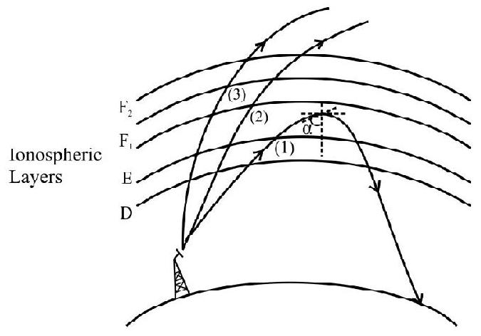
(1) (Relative) redfractive index, of the ionospheric layer, between the
(2) (Relative) redfractive index, of the ionospheric layer, between the
(3) Rays (2) and (3) are incident at angles greater than the critical angles for the layers
(4) There are no ions at all, in the ionospheric layers above the layer
Show Answer
Correct answer: (2)
Solution:
The bending of EM waves, via ionospheric reflection, is similar to the phenomenon of total internal refelection. For TIR, we have,
where
For
Hence statements (1) and (3) are incorrect. Statement (4) is also incorrect as the layers mentioned have a relatively low ion………….
Difficult
Propagation of EM Waves
19. Suppose a given TV transmission system (using space wave mode of propagation), were set up in which the sum total
(1)
(2)
(3)
(4)
Show Answer
Correct answer: (3)
Solution:
The line of sight distance, between the two antennas in given by
(
For maximum value of
or
or
Average
Propagation of EM Waves
20. The height of a transmitting antenna, and its ‘redio horizon’, are denoted by
(1)
(2)
(3)
(4)
Show Answer
Correct answer: (1)
Solution:
We known that
We also know that, for a particle starting from rest and having a uniformacceleration a,
The other listed (graphs - pairs) do not match.
Difficult
Propagation EM Waves
21. Let
The minimum time delay between the transmission of a signal, and its ‘receiving back’ on earth, after ‘reflection’ from a geostationary satellite, would be
(1)
(2)
(3)
(4)
Show Answer
Correct answer: (2)
Solution:
For a geostationary satellite, at a height
or
This must equal,
or
The minimum distance the signal has to travel equals
Hence,
Minimum time dalay
Average
Propagation of EM Waves
22. The ‘space wave’ mode of propagation of EM waves is used for LOS communication as well as for ‘satellite communication’. During satellite communication.
(1) The frequencies used are generally in the radio wave and microwave part of the e.m. spectrum; the satellite usually retransmits the signal at a carrier freqeuncy different from the carrier freqeuncy of its incoming signal.
(2) The frequencies used are generally in the infrared and microwave part of the e.m. spectrum; the satellite always retransmits the signal at the same carrier frequency as that of the incoming signal.
(3) The frequencies used are generally in the radio and microwave part of the e.m. spectrum; the satellite always transmits the signal at the same carrier frequency as that of the incoming signal.
(4) The frequencies used are generally in the infrared part of the e.m. spectrum; the satellite usually retransmits the signal at a carrier freqeuncy different from the carrier frequency of the incoming signal.
Show Answer
Correct answer: (1)
Solution:
The frequencies, used in satellite communication, are generally in the radio and microwave parts of the e.m. spectrum.
The satellite receives the signal, amplified and usually refransmitts it at a carrier frequency different from the carrier frequency of the incoming signal. It does so to avoid intermixing of the outgoing signal.
Average
‘Line of Sight’ Propagation E.M. Waves
23. For the ‘combination’ of a transmitting antenna, of height
(1)
(2)
(3)
(4)
Show Answer
Correct answer: (1)
Solution:
The radio horizon is given by
In the first case, then
In the second case, if
We have,
Easy
Bandwidth of Transmission Media
24. The bandwidth of three different transmission media, say, A, B, C, are
(1) (wire/a co-axial cable), optical fibres and air (or space)
(2) air (or sapce), (wire / a co-axial cable) and optical fibres
(3) a (wire co-axial cable); air (or space) and optical fibres
(4) air (or space); (wire / a co-axial cable) and optical fibres
Show Answer
Correct answer: (3)
Solution:
(Wires / Co-axial cables) have relatively small bandwidths _ of the order of
Air (or space) has bandwidth ranging from a few
Easy
Modulation
25. It is known that the height of a transmission antenna should preferably be of the order. The length of antenna at a place is
(1)
(2)
(3)
(4)
Show Answer
Correct answer: (4)
Solution:
Length of antenna required
Easy
‘Need for Modulation’
26. If an audio signal were to be transmitted directly over a long distance, the minimum size of transmitting antenna would be of the order of
(1)
(2)
(3)
(4)
Show Answer
Correct answer: (4)
Solution:
Considering the upper limit of the audio frequency range (i.e.
The optimum size of the antenna being, of the order of
Easy
Amplitude Modulation
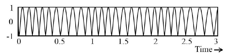
27. A carrier wave
(1) A
(2) B
(3) C
(4) D
Show Answer
Correct answer: (4)
Solution:
There is no change in the frequency of the carrier wave when it is aplitude modulated by a message signal. However, the peak value of its amplitude (on the positive as well as the negative side) does not remain constant; it varies as per the variations of the message signal. It is only diagram (D) that shows (correctly) the variations in the amplitude (as per the message signal) of the carrier wave.
Average
Amplitude Modulation
28. A carrier wave
is amplitude modulated by a message signal
The AM wave has a modulation index of 0.5 and side bands of frequencies
(1)
(2)
(3)
(4)
Show Answer
Correct answer: (3)
Solution:
We know that
Modulation index
Also ‘side bands’ have frequencies
and
These give
and
Difficult
Amplitude Modulation
29. A carrier wave
is amplitude modulated by a message signal
The equation, for the (amplitude) modulated wave, and the rms value of its amplitude (over the time interval 0 to
(1)
(2)
(3)
(4)
Show Answer
Correct answer: (2)
Solution:
When a carrier wave is amplitude modulated, by message signal, it is the amplitude, of the carrier wave, that is made to vary in accordance with the message signal. Hence the equation for the amplitude modulated wave is
The rms valus of its amplitude is the rms value of the term
i.e. square root of the average of
Difficult
Amplitude Modulation
30. A carrier wave
is amplitude modulated by a message signal
The amplitude modulated wave can be regarded as made up of the
(1) original carrier wave of frequency
(2) original carrier wave of frequency
(3) modified carrier wave of frequency
(4) modified carrier wave of frequency
Show Answer
Correct answer: (1)
Solution:
The equation of the amplitude modulated carrier wave is
Hence the amplitude modulated carrier wave can be regarded as made up of the
(i) original carrier wave of amplitude
(ii) two sinusoidal waves, each of amplitude
Difficult
Amplitude Modulation
31. In the process of amplitude modulation, the modulating (message) signal
(1) power amplifier, square law device and band pass filter.
(2) band pass filter, power amplifier and square law device.
(3) square law device, band pass filter and power amplifier.
(4) power amplifier, band pass filter and square law device.
Show Answer
Correct answer: (3)
Solution:
The sequence of (amplitude) modulation, of the carrier wave by the message signal is as per the block diagram shown here.
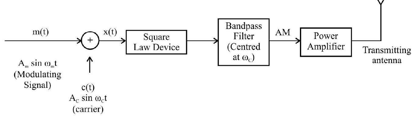
After adding the message signal
The output of the band pass filter is followed by a power amplifier. This provides it the necessary power. This power argumental signal is than fed into an appropriate sized transmitting antenna which than radiates it out into space.
Easy
Modulation
32. The two well known types of modulation are the amplitude modulation (AM) and frequency modulation (FM). In each of these, one of the characterstics (amplitude
(1) During
(2) During AM, it is
(3) During AM, it is
(4) During AM, it is
Show Answer
Correct answer: (2)
Solution:
During amplitude modulation, it is the amplitude, of the carrier wave, that varies in accordance with the variation of the ‘amplitude’ of the message signal.
During frequency modulation it is the frequency, of the carrier wave, that varies is accordance with the variations of the ‘amplitude’ of the message signal.
Average
AM and FM
33. The following are some statements about amplitude modulation (AM) and frequency modulation (FM):
(A) The SNR (Signal to noise ratio) is better for AM as compared to FM.
(B) During FM, linear amplifiers are not required because FM signals have a constant amplitude.
(C) The operating range of AM as well as FM are nearly of the same order.
(D) The fidelity of reception, for FM, is much better than for AM.
The correct statement/s, from the above, is / are the statement / s.
(1) (B) only
(2) (B) and (D) only
(3) (A) and (C) only
(4) (C) only
Show Answer
Correct answer: (2)
Solution:
Statement (A) is incorrect; it is the other way round.
Statement (C) is incorrect; the operating range of FM is higher than that of AM.
Statement (B) and (D) are both correct statements.
Average
AM and FM
34. The following are some statement about AM (amplitude modulation) and FM (frequency modulation):
(A) The circuitary for AM is more complex than that for FM.
(B) The bandwidth of the signals, during AM, is twice the freqeuncy of the message signal.
(C) The bandwidth of the signals, during FM, is much more than twice the frequency of the message signals.
(D) During frequency modulation, the frequency of the carrier wave varies in accordance with the frequency of the message signals.
The correct statement’s, from the above, is / are the statement / s.
(1) (A) and (C)
(2) (B) only
(3) (D) only
(4) (B) and (C)
Show Answer
Correct answer: (4)
Solution:
Statement (A) is incorrect; it is the other way round.
Statement (D) is incorrect; during FM, the frequency of the carrier wave varies in accordance with the ‘amplitude’ of the message signal.
Statement (B) and (C) are both correct. During AM, the sideband frequency being
During FM, the bandwith of the signal is much higher than
Average
Bandwidth
35. A carrier wave of frequency
The bandwidth of the resultant AM carrier wave can be
(1)
(2)
(3)
(4)
Show Answer
Correct answer: (2)
Solution:
The Am carrier wave has, in addition to its own carrier frequency, two sidebands of frequencies
Its bandwidth is, therefore, twice the frequency of the modulating (message) signal. In the given case, the message signal contains
Difficult
Bandwidth
36. The carrier waves
(1) More for the wave
(2) Similar for both the waves
(3) In the ratio
(4) In the ratio 3:1, for the waves
Show Answer
Correct answer: (2)
Solution:
We know that the bandwidth, of an AM carrier wave, is twice the frequency of its modulating (or message) signal. It does not depend on the frequency of the carrier wave itself.
Here the bandwidth, in the two cases, is given to be identical. This implies taht the ‘message signals’, in the two cases, are similar. We can, therefore, take the ‘amount of information’, carried by the two carrier waves (of different frequencies) to be similar.
Difficult
Amplitude Modulation / Bandwidth
37. A carrier wave,
is amplitude modulated by a given sinusoidal volts message signal. The resultant (AM) carrier wave has a modulation index of
(1) on
(2) on
(3) on
(4)
Show Answer
Correct answer: (2)
Solution:
We know that
Modulation index,
Further, for an (AM) carrier wave,
Bandwidth
Easy
Amplitude Modulation
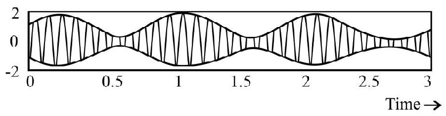
38. The amplitude modulated wave, shown here, is processed (at the receiver end), successively, into the forms (a) and (b), shown alongside.

The devices, used for getting the AM input wave into the forms (a) and (bv), are known, respectively, as
(1) rectifier and transducer
(2) rectifier and envelope detector
(3) transducer and evelope detector
(4) transducer and rectifier
Show Answer
Correct answer: (2)
Solution:
At the receiving end, the AM intant wave is first rectified by using a rectifier. The rectified output is then processed by an envelope detector which removes its RF component and gives its envelope (the original message signal) as its output.
Difficult
Amplitude Modulation and Frequency Modulation
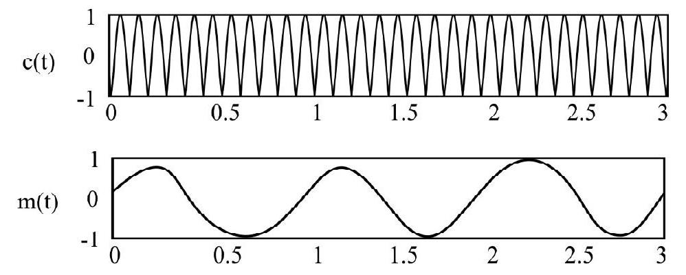
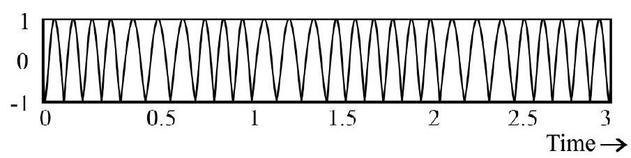
39. A carrier wave
is to be (i) amplitude modulated (ii) frequency modulated by a message signal
The equations (i)
(1)
(2)
(3)
(4)
Show Answer
Correct answer: (1)
Solution:
In amplitude modulation, the amplitude, of the carrier, wave gets modified, in accordance with the ‘instantaneous amplitude’ of the message signal. Hence the instantaneous amplitude, of the carrier wave, has the form
Here there is no change in the frequency of the carrier wave. Hence the equation, for the amplitude modulated carrier wave, has the form
In frequency modulation, it is the frequency of the carrier wave that varies in accordance with the ‘instantaneous amplitude’ of the message signal. Hence the instantaneous frequency has the form
The factor
Here there is no change in the amplitude of the carrier wave. Hence the equation for the frequency modulated carrier wave would have the form
Difficult
Space and Sky Wave Propagation
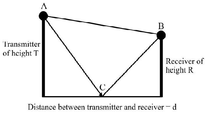
40. In space wave propagation, radio waves (having wavelength
Distance between transmitter and receiver
Assuming that the reflection, from the earth’s surface, takes place from a point midway between the transmitter and the receiver, the total phase difference between the two waves at the receiver will be:
(1)
(2)
(3)
(4)
Show Answer
Correct answer: (3)
Solution:
The direct distance
Similarly, the distance (AC plus CB) traversed by the wave between the transmitter and the receiver will be given by,
Path difference
Phase difference
Since the second wave gets reflected from the earth surface, which a denser medium, therefore, an additional phase difference is of
Total phase difference
Difficult
Space and Sky Wave Propagation
41. In space wave propagation, radio waves (having wavelength
It may be assumed that the reflection, from the earth’s surface takes place from a point midway between the transmitter and the receiver. Considering that the amplitude of both the waves is
(1)
(2)
(3)
(4)
Show Answer
Correct answer: (2)
Solution:
The resultant field strength amplitude can be calculated as follows.
Average
Amplitude Modulation
42. At
(1) 25
(2) 33.3
(3) 75
(4) 100
Show Answer
Correct answer: (2)
Solution:
fraction of total power carried by the sidebands
Therefore, at
Difficult
Space and Sky Wave Propagation
43. In space wave propagation, radio waves (having wavelength
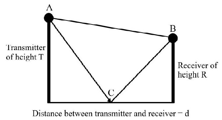
It may be assumed that the reflection, from the earth’s surface takes place from a point midway between the transmitter and the receiver. If the height of the transmitting antenna is doubled, then, the total field strength at the receiver will:
(1) Remain same
(2) Get doubled
(3) Get halved
(4) Increase by
Show Answer
Correct answer: (2)
Solution:
Consider that the amplitude of both the waves is
But since,
Difficult
Amplitude Modulation
44. The modulation index of an amplitude modulated wave is 0.4 . The fraction of total power carried by the central carrier wave will be equal to,
(1)
(2)
(3)
(4)
Show Answer
Correct answer: (3)
Solution:
Power of the central carrier wave
Total power
Average
Amplitude Modulation
45. As the value of the modulation index increases,
(1) Amplitude of the central band increases
(2) Amplitude of the central band decreases
(3) Total power carried by the sidebands increases
(4) Total power carried by the sidebands decreases
Show Answer
Correct answer: (3)
Solution:
Amplitude of the central band is independent of the modulation index.
fraction of total power carried by the central carrier wave
fraction of total power cariied by the sidebands
Therefore, as the modulation index increases, the useful power carried by the central band decreases, but the carried by the sidebands increases.
Difficult
Amplitude Modulation
46. In the modulation index is
(1) 0
(2) 16
(3) 20
(4) 32
Show Answer
Correct answer: (2)
Solution:
Power carried by the central carrier wave
Power carried by each sidebands
Therefore, at
Difficult
Amplitude Modulation
47. Instantaneous voltage of the amplitude modulated wave is given by
Assuming that the effective resistance of the modulator circuit is R, the total power of the amplitude modulated wave will be equal to,
(1)
(2)
(3)
(4)
Show Answer
Correct answer: (4)
Solution:
The instantaneous voltage of the amplitude modulated wave can be written as,
Power of the central carrier wave
Power of the two sidebands
Total power
Easy
Amplitude Modulation
48. In a communication system, the process of modulation is done at the
(1) Transmitter
(2) Receiver
(3) Channel between the transmitter and receiver
(4) Both transmitter and receiver
Show Answer
Correct answer: (1)
Solution:
It is necessary to modulate the (usual) low frequency message signals before they can be transmitted for communication over large distances.
Easy
Amplitude Modulation
49. Im aplitude modulation,
(1) Amplitude of the low frequency carrier signal is varied in accordance with the high frequency message signal
(2) Amplitude of the high frequency carrier signal is varied in accordance with the low frequency message signal
(3) Amplitude of the low frequency carrier signal is varied in accordance with the high frequency carrier signal
(4) Amplitude of the high frequency carrier signal is varied in accordance with the low frequency carrier signal
Show Answer
Correct answer: (2)
Solution:
We need a high frequency carrier wave for effective transmisstion of low frequency message signals in amplitude modulation, it is the amplitude of the high frequency carriers wave that is varied in accordance with the low frequency message signal.
Average
Amplitude Modulation
50. Suppose the carrier wave is modulated in accordance with the amplitude of a message signal.
The modulation index is
(1)
(2)
(3)
(4)
Show Answer
Correct answer: (3)
Solution:
Modulation index
Amplitude of the amplitue modulated wave will be given by,
Average
Amplitude Modulation
51. Suppose the carrier wave is modulated in accordance with the amplitude of a message signal.
The modulation index is
(1)
(2)
(3)
(4)
Show Answer
Correct answer: (4)
Solution:
Modulation index
Amplitude of the amplitue modulated wave will be given by,
Instantaneous voltage of the amplitude modulated wave will be equal to,
Average
Amplitude Modulation
52. Suppose the carrier wave is modulated in accordance with the amplitude of a message signal.
The modulation index is
The bandwidth of the amplitude modulated wave is equal to,
(1)
(2)
(3)
(4)
Show Answer
Correct answer: (1)
Solution:
Instantaneous voltage of the amplitude modulated wave is represented by,
This implies that in addition to the original central frequency, there exist side bands in an amplitude modulated wave. The frequency of upper sideband is equal to,
Bandwidth
Difficult
Amplitude Modulation
53. An amplitude modulated wave is represented by,
For this wave, one can say that
(1) Frequency of the upper sideband is
(2) Frequency of the upper sideband is
(3) Frequency of the upper sideband is
(4) Frequency of the upper sideband is
Show Answer
Correct answer: (3)
Solution:
According to the expression,
Frequency of the modulating wave
Frequency of the carrier wave
Therefore,
Frequency of the upper sideband
Frequency of the lower sideband
Average
Amplitude Modulation
54. An amplitude modulated wave is represented by,
The bandwidth of the amplitude modulated wave is equal to,
(1)
(2)
(3)
(4)
Show Answer
Correct answer: (2)
Solution:
According to the expression,
Frequency of the modulating wave
Frequency of the carrier wave
Therefore, bandwidth
Average
Amplitude Modulation
55. An amplitude modulated wave is represented by,
The minimum and the maximum amplitude of the amplitude modulated wave will be respectively equal to,
(1) 0,1 units
(2) 0,4 units
(3) 3.2 units and 4.8 units
(4) 1.6 units and 8 units
Show Answer
Correct answer: (2)
Solution:
Modulated Index
Minimum amplitude
Maximum amplitude
Easy
Amplitude Modulation
56. The amplitude of a carrier wave, having a peak amplitude of
(1) 0
(2) 0.25
(3) 0.5
(4) 0.75
Show Answer
Correct answer: (3)
Solution:
Modulation index
Easy
Amplitude Modulation
57. An amplitude modulated wave is represented by,
Amplitude of the sidebands will be equal to,
(1)
(2)
(3)
(4)
Show Answer
Correct answer: (1)
Solution:
Instantaneous voltage of the amplitue modulated wave is represented by,
Here,
Modulation
Therefore, amplitude of the sidebands


