Learning Objectives
After going through this unit, you will be able to understand and use:
- Ray optics; using the rectilinear propagation of light.
- Law ofreflection and refraction and their aplications.
- Explain the refraction at a spherical surface.
- Derive the relation between position of object, image and center of curvature - The mirror formula.
- To use the co-ordinate convention of signs.
- Explain the image formation of object of finite size-The transverse magnification.
- Distinguish between the absolute and the relative refractive index and state Snell’s law.
- Explain the passage of monochromatic light in a parallel slab - (1) no net deviation (2) only lateral displacement.
- Derive the formula relating the real and the apparent depth.
- Explain total internal reflection (T.I.R.). Applications of T.I.R.
- Explain passage of monochromatic light through a prism. Deviation and minimum deviation.
- Passage of white light through a prism. Dispension of light. Deviation, angular dispersion and dispersive power.
- The refraction of light at a spherical surface. The refraction formula.
- Use the refraction formula at a spherical surface more than once.
- Derive and use the lens maker’s formula. The convering or diverging nature of convex and concave lens.
- The lens formula. Transverse magnification.
- Explain the characterstics of image of a real object due to a (1) convex lens (2) concave lens.
- Define the power of a lens.
- Explain the co-axial combination of thin lenses in contact.
- Use the reflection and refraction formula for a combination of lenses, mirrors etc.
- Explain the optical instruments. (1) the microscope and (2) the telescope and their magnifying power.
- Use the concepts of wave motion.
- Explain the Huyghen’s principle and its uses.
- Interference of light. Distinguishing between constructive and destructive interference.
- Explain the condition to sustained interference-The coherent sources.
- Explain the Young’s double slit experiment. Location of bright and dark fringes. Derive the formula of the fringe width and intensity variation in interference pattern.
- Explain the phenomenon of diffraction of waves and how to observe diffraction of light?
- Derive the relation for the half-angular width and the radius of the central maximum.
- What is polarisation? Explain that only transverse waves can be polarised.
- Distinguish between polariser and analyser. The transverse nature of light.
- Explain the polarisation due to reflection. The Brewster’s law.
- State and explain Malu’s law and its applications.
Introduction
The study of optics is commonly devided into two parts; i.e.
(1) Geometrical or ray optics
and (2) Wave optics
We describe the two heads one by one.
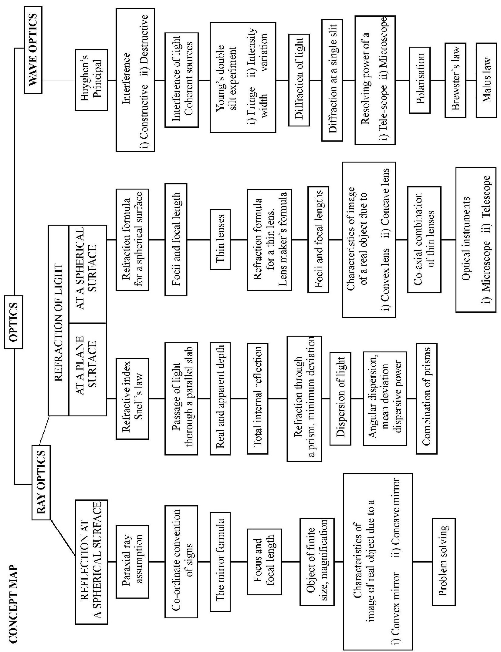
Geometrical or ray optics makes use of rectilinear propagation of light in a homogeneous, isotropic medium. The straight line path light follows is known as a ray. A collection of rays constitue a beam. The beam of light is (1) parallel (2) convergent or (3) divergent as shown in Figure- 1 (a), (b) and (c).
Reflection of Light
A beam of light incident on a smooth surface is thrown back into the same medium by the surface. This is known as reflection of light. The laws of reflection are:
(a) Incident ray; reflected ray and normal at point of incidence lie in same plane.
(b) The angle of incidence (i) is equal to the angle of reflection ( ); i.e. .
Characteristics of Reflection by a Plane Mirror
1. The image formed by reflection of a real object is virtual; erect and of same size as object.
2. The image formed is lateraly inverted i.e. left of object appears right in image and vice-versa.
3. The image formed is as far behind the mirror as the object is in front of mirror.
4. When a plane mirror turns through an angle ; the reflected ray turns through an angle .
5. The minimum length of a plane mirror, required to see the full size image of a person; by himself; is half the size of the person.
6. For two plane mirrors inclined at an angle with one another, the number of images, ; observed due to multiple reflection of a point object placed between the mirrors is
7. A ray of light incident at an angle , undergoes a deviation , due to reflection at a plane surface.
Example-1:
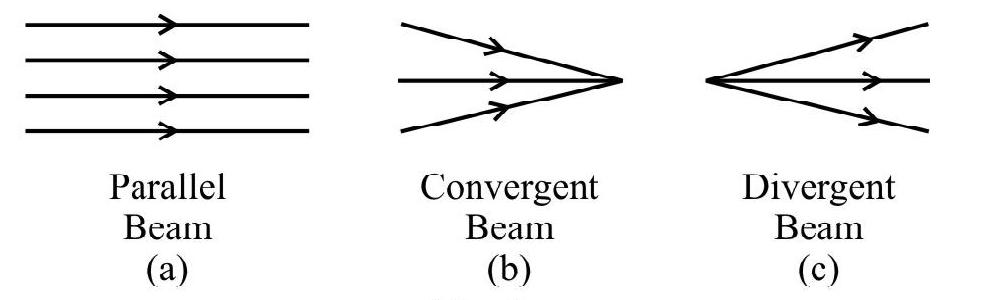
Two plane mirrors are inclined to one another at an angle . A ray of light incident at an angle is reflected first by one mirror and then by other. The total deviation produced is
(1)
(2)
(3)
(4)
Show Answer
Solution:
As shown in Figure- and are the two mirrors inclined to one another at angle is the incident ray on at an angle . The reflected ray from is incident on the second mirror at an angle . The final reflected ray is . Let be the total deviation and and be the deviation due to and respectively.
Then , and
,
Now from
or
Hence
Note that is independent of .
Hence option (4) is correct.
Example-2:
A point object is placed between two plane mirrors as shown in Figure- 3. The distance of the first three images formed due to multiple reflections from mirror are

Figure- 3
(1)
(2)
(3)
(4)
Show Answer
Solution:
The first image formed is behind . Mirror forms an image of the object behind it. This acts as object at a distance of from . Second image formed by is behind and so on.
Hence the option (1) is correct.
SPHERICAL MIRRORS
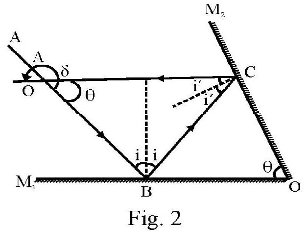
A spherical mirror is a part of a hollow sphere, one surface of which is silvered. Figure- 4 (a) shows a hollow sphere of center ; radius . The shpere is cut by plane . is a part of a spherical surface. Figure- 4 (b) and (c) show a convex and a concave mirror respectivelv. For a spherical mirror.
(1) is the apertere of mirror. It measures the size of mirror.
(2) is the center of curvature and is the radius of curvature.
(3) Mid point , is known as the pole of the mirror.
(4) The line joining the pole; , and center of curvature , is the principle axis of the mirror.
Reflection at a Spherical Mirror
In the Figure- 5 AOA’ is a concave mirror. is center of curvature. is point object placed on principal axis. PA is one incident paraxial ray at point A of mirror. is the normal at point of incidence angle of incidence. In Figure- is reflected ray. angle of reflection. In accordance with law of reflection .
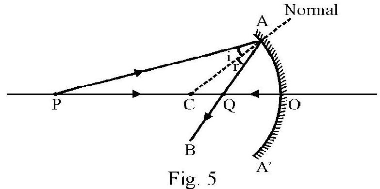
To locate position of image formed by the mirror we consider at least one more incident ray say PO. This ray is incident normally and therefore is reflected back. In Figure- 5 the two reflected rays meet at point Q. We say is the real image of due to reflection by the spherical mirror.
The Co-ordinate Convention of Signs
To obtain a single, convenient relation between the location of object and image we now use co-ordinate convention of signs. The basic features of co-ordinate convention are:
(1) Incident rays are always drawn from left to right.
(2) The pole of spherical mirror or optical center of lens is chosen as origin of co-ordinates.
(3) The principal axis in the direction of incident ray is the direction of positive -axis.
(4) Anticlockwise angles are positive and clockwise angles are negative.
(5) In a direction perpendicular to principle axis, the direction above principal axis is the direction of positive axis.
In using co-ordinate convention, note, distance of object, image; center of curvature etc. is a pure number. There is no + or - sign attached to a distance. However the position of an object; image, center of curvature etc., is the co-ordinate of the point considered in the co-ordinate system chosen according to the rules of the co-ordinate convention of sign. Position is appropriate distance with a + or -sign prefixed.
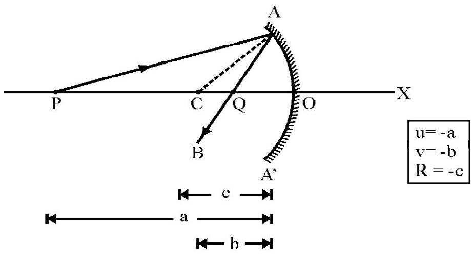
Figure- 6
The mirror formula is the relation between the object position ; the image position and the radius of curvature, (i.e position of the center of curvature C); of the mirror. Figure- 6 shows image formation of a point object due to a concave mirror. distance of object from the mirror. distance of the image formed radius of the sphere of which mirror is part. Choosing a co-ordinate system with as origin and as positive -axis (i.e. in accordance with the co-ordinate convention of signs; we have
The object position (i.e. co-ordinate of )
The image position (i.e. co-ordinate of )
The radius curvature (i.e. co-ordinate of )
Please note the sign attached before appropriate distance. It can be shown that
aligned (1) is known as the mirror formula.
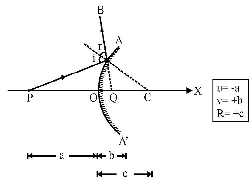
Figure- 7
Figure- 7 shows reflection at a convex mirror. The reflected ray does not actually meet principal axis, but reflected ray appears to meet principal axis at . is the virtual image of the real object . Valueof and in terms of distances and is shown inside box in Figure- 7. For convex mirror also, the mirror formula is
This is same as aligned (1). In other words same formula is applicable for concave as well as convex mirror. However, etc. have to be asinged appropriate + or - sign in accordance with the sign convention.
Principal Focus and Focal Length
Consider an incident beam, parallel to principal axis. The reflected rays
(1) for concave mirror; actually meet principal axis at point as shown in Figure- 8 (a).
(2) for convex mirror; appear to meet principal axis at point as shown in Figure- 8 (b).
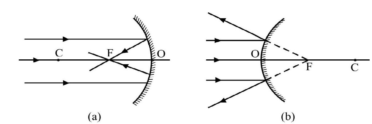
Figure- 8
is known as the principal focus of the mirror. The position of gives the focal length (f) of the mirror. It can be shown that lies in the middle of and . Expressed mathematically
The mirror formula in terms of focal length is
For an incident ray that passes or appears to pass through , the reflected ray is parallel to principal axis as shown in Figure- 9 (a) and (b).
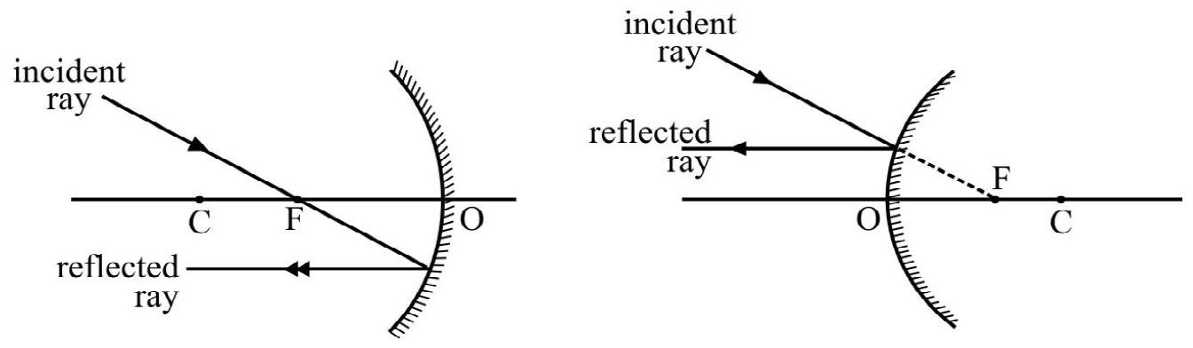
Figure- 9
Images of an Object of Finite Size
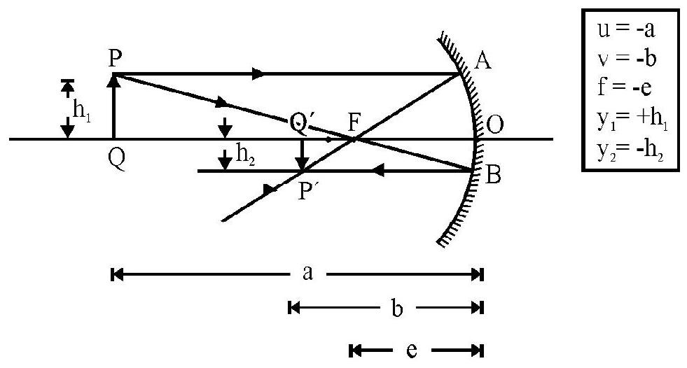
Figure- 10
Figure- 10 shows an object of length placed perpendicular to principal axis. ’ of lengh is the real, inverted image formed by concave mirror. is the focus of mirror. The appropriate distances and positions are shown in Figure- 10. The relation between position of object, image and focal length is same as given by aligned (4).
The relation between length of object and image formed is expressed by defining transverse magnification, . Let and to be the size of the object and image. According to co-ordinate convention of signs.
The transverse magnification is ratio of the size of the image and the size of the object, i.e.
It can be shown that
The magnification has both a sign and magnitude. The sign of will give whether image is erect or inverted. If is a negative number image formed is inverted with respect to object and if is a positive number the image formed is erect with respect to object. The magnitude of ; gives information regarding length of image. If , the image formed is enlarged and if the image formed is diminished with respect to the object.
Characteristics of Image of a Real Object due to Reflection by a Concave Mirror
The following table gives position, nature of image as a real object is moved from infinity towards the mirror
| S.No. |
Position of Object |
Image |
|
|
|
Position |
Nature |
| 1. |
At infinity |
At focus |
real, inverted, highly diminished |
| 2. |
Between and 2F |
Between and |
real, inverted, diminished |
| 3. |
At 2F |
At |
real, inverted, same size as object |
| 4. |
Between and |
Beyond |
real, inverted, enlarged |
| 5. |
At |
At infinity |
real, inverted, highly enlarged |
| 6. |
Between and |
Behind the mirror |
virtual, erect and enlarged |
Characteristics of Image of a Real Object due to Reflection by a Convex Mirror
A convex mirror forms a virtual, erect and diminished image of a real object; irrespective of the position of the object. Figure- 11 shows image formation by a convex mirror.
An Important Note:
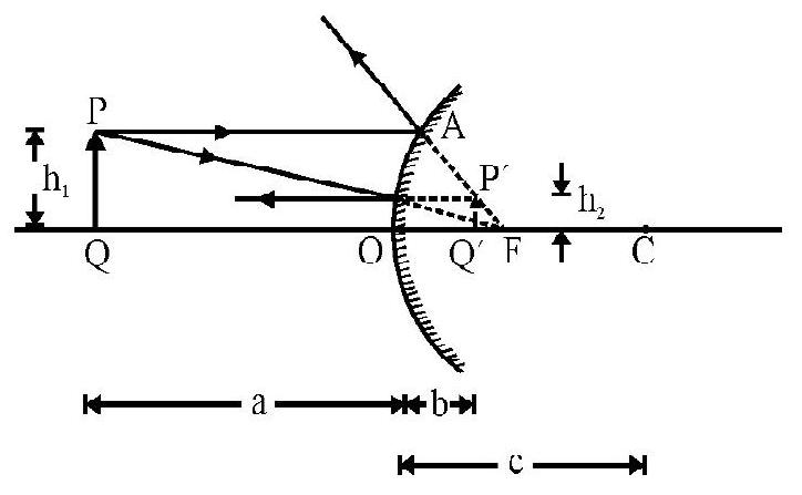
Figure- 11
For solving problems using mirror formula, the following ‘guide lines’ are very use full.
(i) The positions of given parameter like object position, image position, focus etc. must be given their appropriate + or - sign in accordance with sign convention.
(ii) The position or size of the unknown parameter will be obtained using aligned (4) and (5). The sign and magnitude of unknown parameter must be properly intepretted.
The following table gives signs & their interpretation of commonly occuring parameters.
| 1. |
Mirror |
1) Concave
2) Convex |
and f are negative
and are positive |
| 2. |
Object |
1) Real
2) Virtual |
is negative
is positive |
| 3. |
Image |
1) Real
2) Virtual |
is negative
is positive |
| 4. |
Magnification |
1) Positive
2) Negative
3)
4) |
Image is erect
Image is inverted
Image is enlarged
Image is diminished |
Example-3:
A concave mirror of radius has an object of length placed perpendicular to principal axis at a distance of (i) (ii) . In each case what is position, nature and length of image formed by the mirror?
Show Answer
Solution:
Radius of curvature of mirror
Case-I:
Using mirror formula
Negative sign of indicates image formed is real at a distance of from the mirror.
Negative sign of indicates inverted image the image formed is diminished. Also
Case-II:
Given ?
or
The positive sign of indicates virtual image. The image is behind the mirror. Also
The positive sign of indicates erect image. Also the image formed is enlarged. Also
Example-4:
A spherical mirror forms an image half the length of the object. The image is at a distance of from the mirror. What is nature and focal length of the mirror?
Show Answer
Solution:
We are given . We do not know whether image formed is real or virtual; therefore, we will consider both cases one by one.
Case-I: Image formed is real
Since image is real; it must be inverted; therefore . Also . We know
From mirror formula
The negative sign of f indicates that the mirror is a concave mirror.
Case-II: Image formed is virtual
The virtual image formed is erect, therefore , and
or or
Using mirror formula
The positive sign of f indicates convex nature of the mirror.
Example-5:
A beam of light converges towards a point as shown in Fig 12(a). A convex mirror is placed in the path of beam at disatnce of in front of . What is position and nature of image formed? Radius of curvature of mirror is .
Show Answer
Solution:
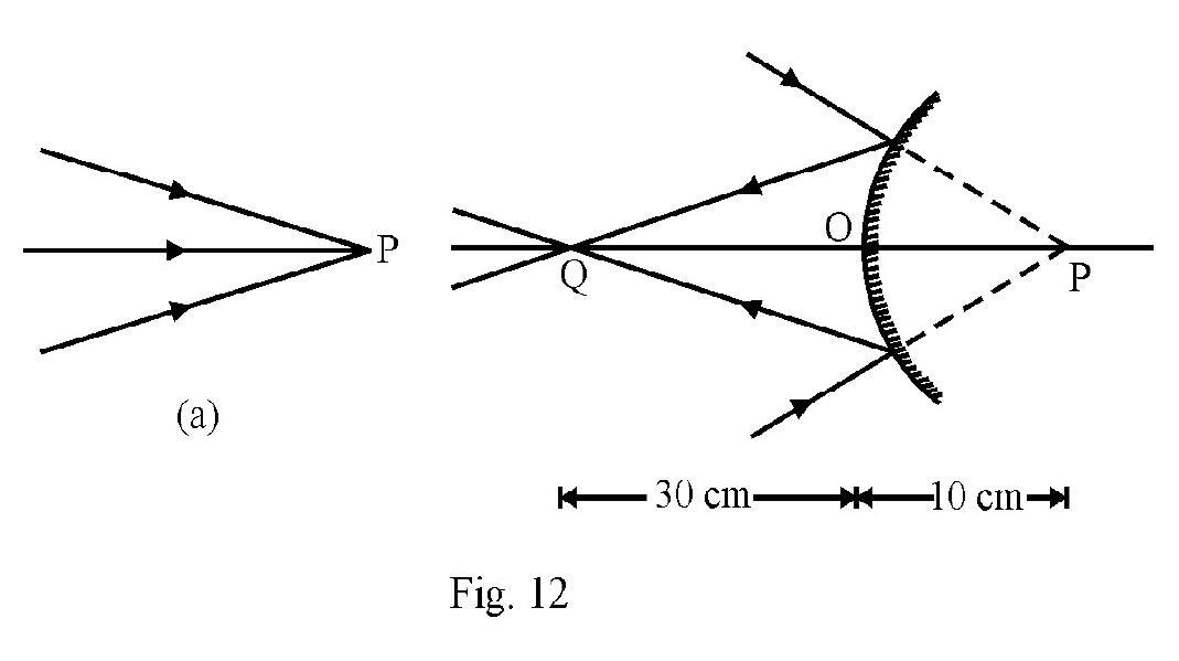
Figure- 12 (a) shows the incident beam converging at point P. Figure- 12 (b) shows convex mirror placed in the path of incident convergent beam. The incident rays meet convex mirror before reaching point . Now acts as a virtual object. Therefore,
Using the mirror formula
The negative sign of indicates a REAL image! This is shown in Figure- 12 (b). The interesting point to be noted specially is that convex mirror can from a real image of an appropriately placed virtual object.
Example-6:
A spherical mirror projects image of an object placed in front on a screen. The length of image is twice that of the object. The distance between object and image is . What is
(i) position of object and image.
(ii) nature and power of the mirror?
Show Answer
Solution:
Let and be the distance of the object and image from the mirror. Since image is projected on screen it is a real and inverted image. Therefore using sign convention
Given distance between object and image is . Therefore
or or and
Let be the focal length of the mirror. Using mirror formula
or
The negative sign of f indicates that the mirror is a concave mirror. The power of mirror
The object is placed in front of the mirror and image is at a distance of from the mirror.
Example-7:
A concave mirror of focal length and a convex mirror of focal length are placed coaxially facing each other and apart. A point object is placed in between the mirrors; on their common axis; from the concave mirror. Find the position and nature of image formed due to first reflection at concave mirror and then convex mirror.
Show Answer
Solution:
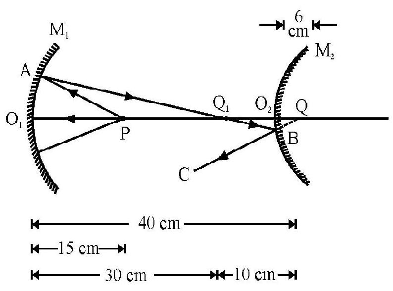
Figure- 13
Figure- 13 shows and as the two mirrors. is object on principal. axis at a distance of from . The incident ray PA on concave mirror is moving from right to left. This is not in accordance with co-ordinate convention of signs. To make consistent use of co-ordinate convention imagine the diagram to be rotated by as far as concave mirror is concerned. Then for concave mirror.
From the mirror formula
The negative sign of indicates real nature of image formed by concave mirror. The incident ray PA and reflected ray , is shown in Figure- 13
acts as a real object for convex mirror. The ray is incident on convex mirror. In Figure- 13 this is in accordance the co-ordinate convention of signs. For convex mirror.
The positive sign of indicates virtual nature of the final image . The incident and reflected rays for convex mirror as shown in Figure- 13.
Example-8:
A thin rod of length is placed along the optic axis of a concave mirror of focal length such that its image which is enlarged, real and just touches the rod. Calculate magnification.
Show Answer
Solution:
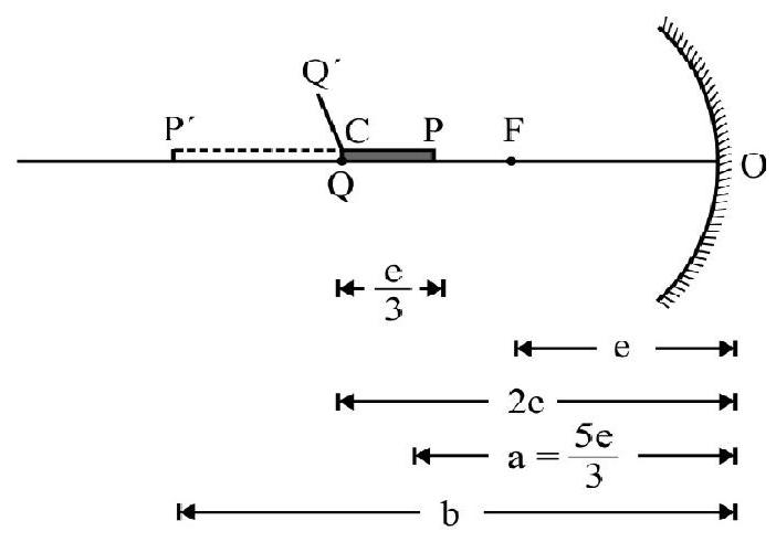
Figure- 14
Let magnitude of focal length of concave mirror. distance of center of curvature from is the length of object placed along principal axis. The image formed is . For end of rod its image coincides with itself, therefore, is at center of curvature, , of mirror. For end
In accordance with co-ordinate convention of signs
Using mirror formula we have
The length of image
The magnitude of axial magnification
Example-9:
Image of an object approaching a convex mirror of curvature along its optical axis is observed to move from to in . What is the average speed of object is ?
Show Answer
Solution:
Let at ; the object be at a distance of meter from convex mirror. The image formed is at a distance from the mirror. Obviously
Given,
Using mirror formula, we have
Similarly is distance of object from mirror at . The image distance . Therefore
Using mirror formula
The distance moved by object in is . Therefore,
The average speed of object
REFRACTION OF LIGHT-SNELL’S LAW
Whenever light goes from one medium to another medium; in general; the light bends either towards or away from the normal at the point of incidence. This is known as refraction of light. Refraction oflight is shown in Figure- 15 (a) and (b).
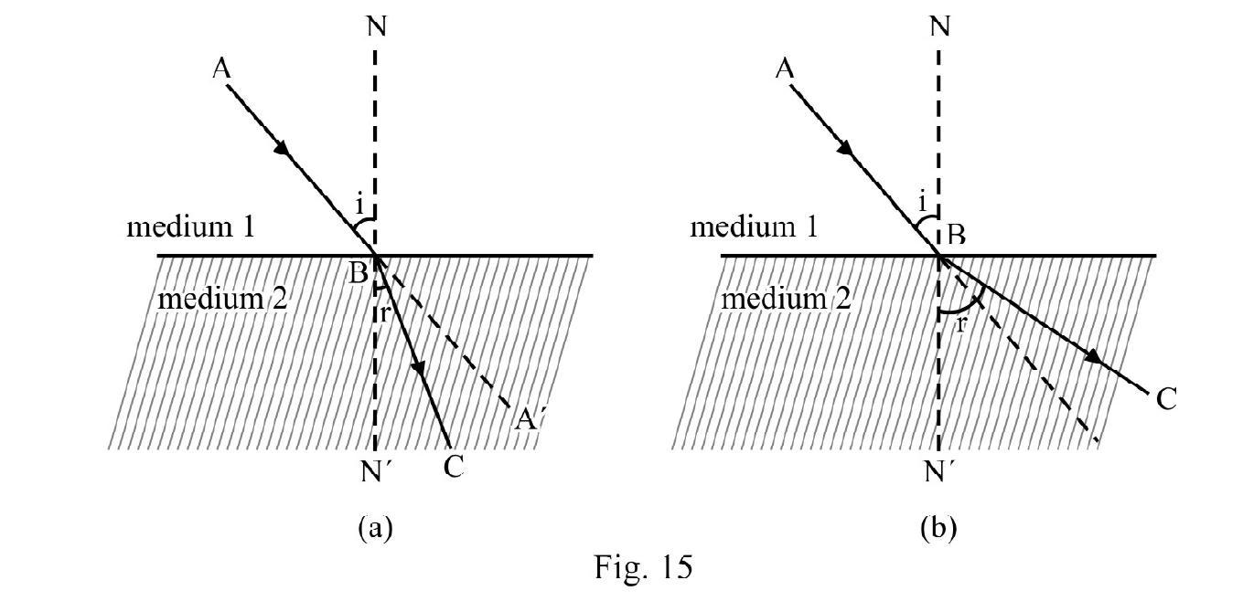
In Figure- 15 (a) we say medium 2 is optically denser than medium 1; whereas in Figure- 15 (b) medium 2 is optically rarer than medium 1.
The optical density of a medium is measured by the absolute refractive index (n) of the medium. By definition
and represent the relative permittivity and the relative permeability of the medium. is always less than hence absolute refractive index can never be less than one.
Refraction of light obey’s Snell’s law. According to Snell’s law.
(1) The incident ray; the refracted ray and normal at point of incidence lie in same plane.
(2) The ratio of sine of angle of incidence (i) and sine of angle of refraction ( ) is a constant. Expressed mathematically
Let be the absolute refractive index of medium 1 known as incident space and the refractive index of medium 2, known as refracted space. According to Snell’s law.
is the relative refractive index of medium 2 with respect to medium 1. In aligned (1), and is speed of light in medium 1 and medium 2 respectively. The relative refractive index can be more or less than one. Obviously
In general aligned (2) can be written as
Refraction of Light at a Parallel Slab
In the Figure- is a parallel slab of thickness , having refractive index is a monochromatic incident ray on face PQ at an angle of incidence, i. Figure- 16 shows refracted, ray BC inside slab and the emergent ray CD. is angle of emergence. Applying Snell’s law at point B and C, we have
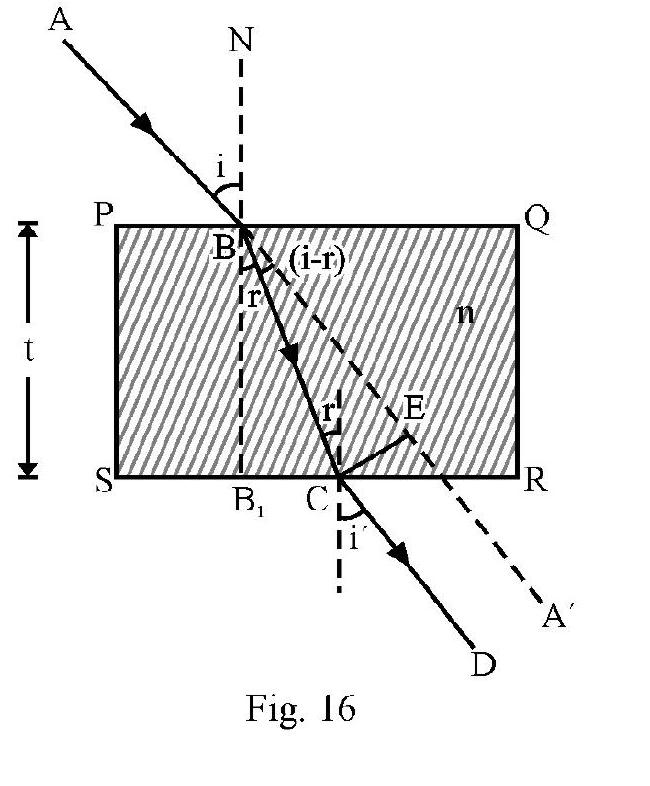
or
The angle of emergence equals angle of incidence. In other words emergent ray is parallel to incident ray . The net deviation due to refraction at both faces of parallel slab is zero. However the incident ray and the emegent ray are not coincident. is the lateral displacement. From Figure- 16 it can be shown that
Refraction Through Multiple Slabs
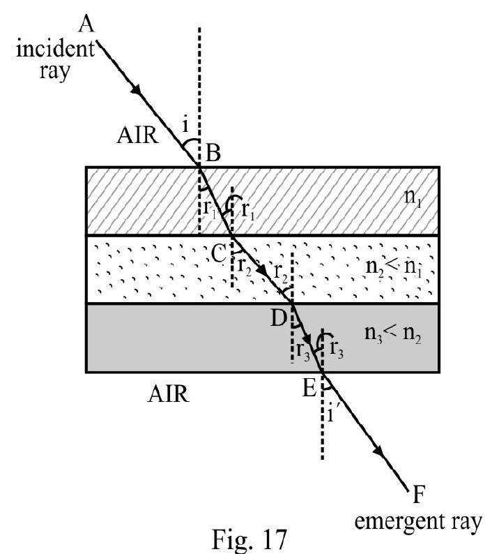
Figure- 17 shows path of incident ray inside parallel slabs of different materials. is angle of incidence and is angle of emergence. Applying Snell’s law repeatedly.
When medium on the upper side and lower side is same [in Figure- 17 it is air]; . If medium above and below is not same, .
Real and Apparent Depth
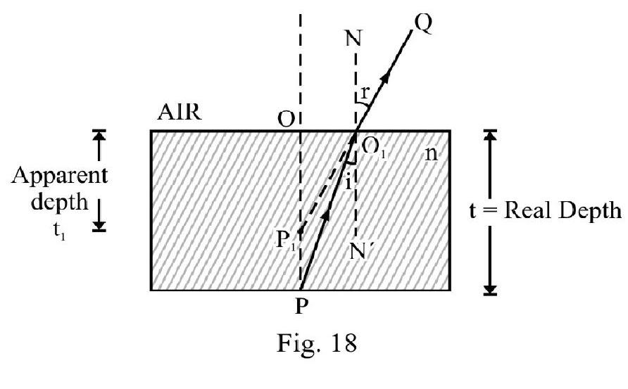
Figure- 18
is a point object at the bottom of a medium of refractive index of real thickness . is an incident ray. The refracted ray bends away from normal, i.e. . The emergent ray appears to come from point is apparent position of as viewed from outside. the apparent depth of . For near normal incidence (i.e. and are small angles; )
For Figure- 18 shown light going from a denser medium to a rarer medium (air) apparent depth viewed from air is less than the actual depth.
In general; if instead of air there is some other medium; the apparent depth may be more or less than the real depth depending to value of refractive indices of media involved. For object at a real depth , inside a medium of refractive index , when viewed from a medium of refractive index ; the apparent depth is
For whereas for .
For a number of media of different thickness and refractive indices as shown in Figure- 19, we have
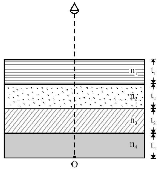
Figure- 19
Total apparent depth
and total apparent shift
is the refractive index of medium of real thickness .
Example-10:
A ray of light in air is incident at angle of on the plane boundary seprating it from a medium. The angle of deviation of refracted ray is . What is refractive index of the medium?
Show Answer
Solution:
Let be refractive index of medium. Incident light goes froma rarer medium(air) to a denser medium. It bends towards normal i.e. . The angle of deviation . Given
From Snell’s law
or
Example-11:
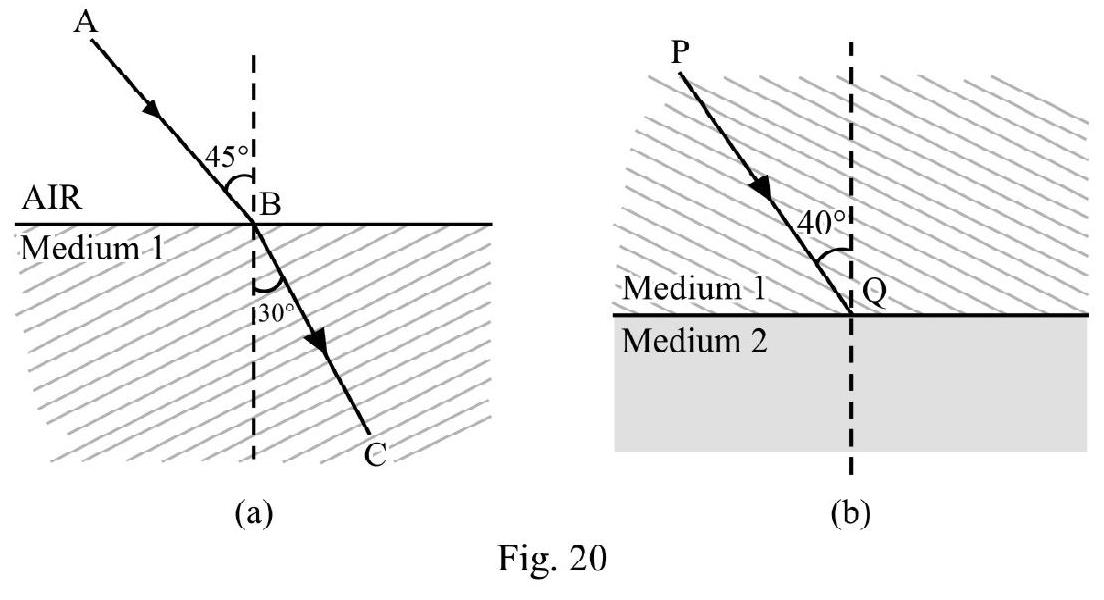
In Figure- 20 (b) the incident ray PQ bends away from normal; suffering a deviatino of . What is speed of light in medium 2? Given .
Show Answer
Solution:
Let be absolute refractive index of medium 1. From Figure- 20 (a); using Snell’s law
In Figure- 20 (b); the angle of refraction . From Snell’s law
The speed of light in medium 2 is
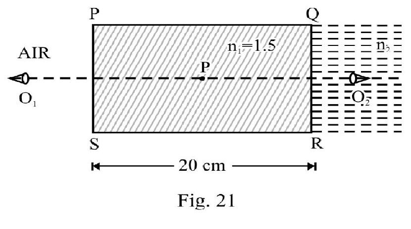
Example-12:
Figure- 21 shows a small bubble, ; trapped insidea glass slab . When viewed from position the bubble appears to be at a distance of from the face through which it is viewed. When viewed from position the bubble appears to be at a distance of from the face of slab nearer the observer. What is ?
Show Answer
Solution:
Let can be the actual distance of bubble from face PS. For observer. ; the apparent distance from PS is . Therefore
The actual distance of bubble from face is . The apparent distance is . Therefore
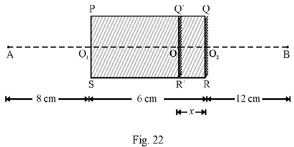
Example-13:
One face of a parallel rectangular slab of a transparent material is silvered. An object is placed at a perpendicular distance of from the unsilvered face of slab. The image of the object is observed at a distance of from the silvered face of slab. What is refractive index of material of slab?
Show Answer
Solution:
Figure- 22 shows slab PQRS. A is object at a distance . The image is formed at a distance . When observed from ; the mirrored face appears to be at . Let be the apparent shift in position of . Now for reflection from ;
Object distance Image distance
From face PS of slab; the real distance of face . The apparent distance . Therefore
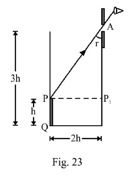
Example-14:
An observer can see through a pin-hole at the top end of a thin glass rod of height placed as shown in Figure- 23. The actual height of beaker is and its radius is . When the beaker is filled with a liquid upto a height of , the observer can see the lower end of the rod. What is of liquid?
(I.I.T 2002)
Show Answer
Solution:
In Figure- 23 QO is incident ray from lower end Q of rod inside liquid. The refracted ray appears to meet rod at end as shown.
angle of incidence at angle of refraction at .
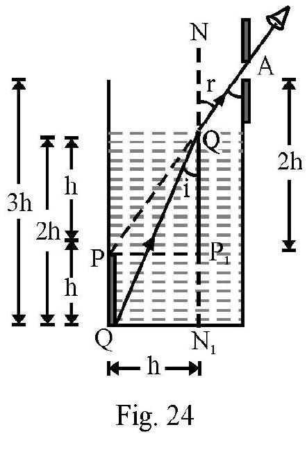
Using Snell’s law
From Figure- 24;
From right angled triangle
From equation (1), (2) and (3) we have
Total Internal Reflection
Figure- 25 shows a monochromatic incident ray going from a denser medium (i.e. medium 1, refractive index ) into a rarer medium(i.e. medium 2 , refractive index ). The refracted ray bends away from
normal i.e. as shown in Figure- 25 (a). On gradually increasing i, also increases. For an angle of incidence ( ) the angle of refraction as shown in Figure- 25 (b). In Figure- 25 (c) ; there is no refracted ray in medium 2 . The entire incident energy is thrown back to medium 1 obeying law of reflection. This is known as total internal reflection (T.I.R). is the critical angle of incidence. Applying Snell’s to Figure- 25 (b); we have
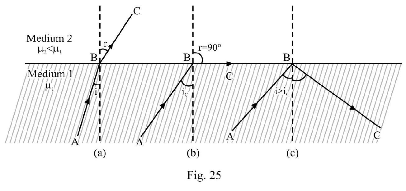
For T.I.R to take place light must go from a denser to a rarer medium.
Total Internal Reflection at Glass - Air Surface
Consider an incident ray going from glass to air. The critical angle of incidence, is
Figure- 26 shows an issoceless right angled glass (refractive index ) prism. is a ray incident normally at face . It goes straight and is incident on face at an angle of incident . Total internal reflection can occur at R. For T.I.R to take place at face AC, i.e. no light emerges out of face . The minimum value of ; should be equal to . Therefore for T.I.R to take place at face
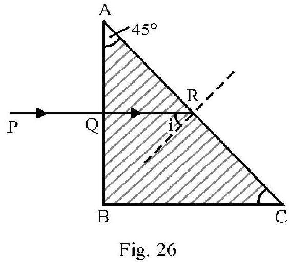
The minimum refractive index of prism is
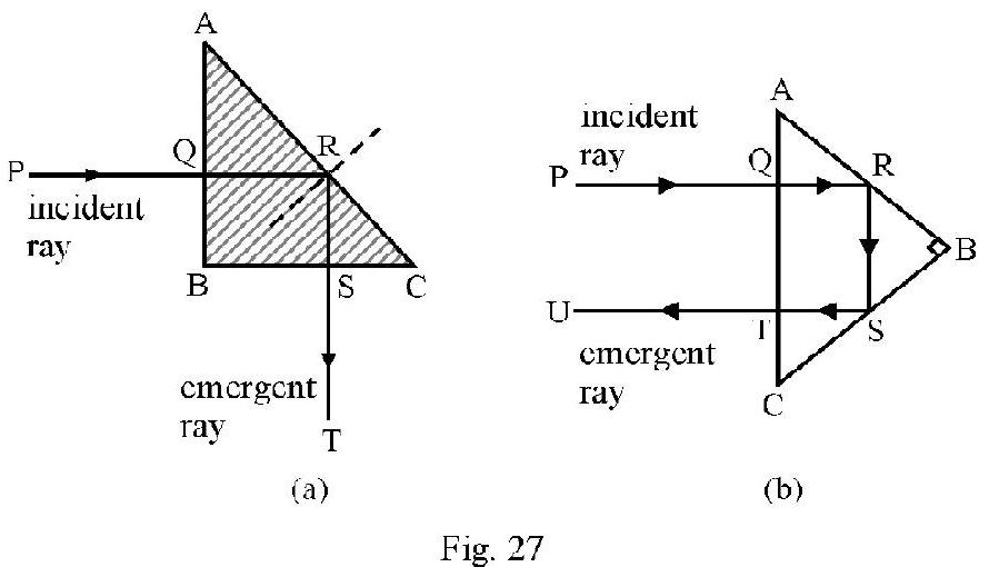
Such a glass issocless prism is known as a totally reflecting prism . Figure- 27 (a) and (b) show how such a prism is used to deviate an incident ray by or .
Total Internal Reflection at Water - Air Surface
Total internal reflection can occur when an incident ray in water goes to air. The critical angle, , is
A fish under water in a pond sees the entire outside world canfired within a cone of angle .
ILLUSTRATIONS OF T.I.R
The optical illusion known as mirage is observed during day time in a hot desert. A thirsty deer, looks around for water. The deer sees a clear inverted image of a distant tree and thinks that the tree is on the bank of a water pond. The deer runs in that direction and on reaching the tree finds no water! The phenomenon of mirage is due to variation of refractive index with temperature. In a ‘hot desert’ during day time the temperature of air layers decreases as one moves upwards from ground. Therefore refractive index of air layers decreases as one moves towards ground. An incident ray from top of a distant tree undergoes refraction from a denser layer to a rarer layer of air and undergoes T.I.R producing a clear inverted image of the tree.
The shinning of diamonds is also due to repeated T.I.R. A ray inside diamond undergoes repeatd T.I.R inside diamond before it emerges out. Take for diamond, the critical angle.
Due to small values of ; repeated T.I.R occures easily inside diamond.
REFRACTION THROUGH A PRISM
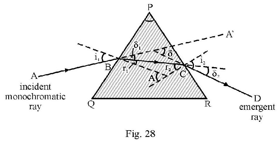
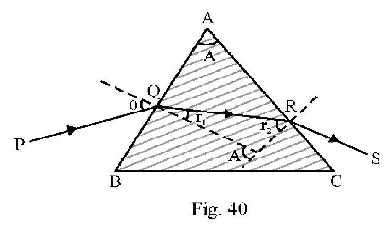
In Figure- is a prism of a material of refractive index is a monochromatic incident ray on face PQ at angle of incidence . Figure- 28 shows refracted ray inside prism and the emergent ray CD. (i.e. angle between the two faces where refraction occurs) is known as the refracting angle, ; of prism. is angle of emergence.
Due to refraction at both faces PQ and PR the incident ray is deviated by an angle .
The angle of total deviation
For a given prism; depends on angle of incidence. Figure- 29 shows vs i graph. From graph we note that there is a particular angle of incidence for which deviation is minimum . It can be shown that for minimum deviated ray.
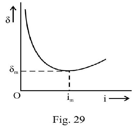
or angle of incident for minimum deviated ray
For minimum deviated ray; the path of ray inside prism is parallel to the base QR of prism as shown in Figure- 30. Applying Snell’s law to the minimum deviated ray; i.e.
and we have
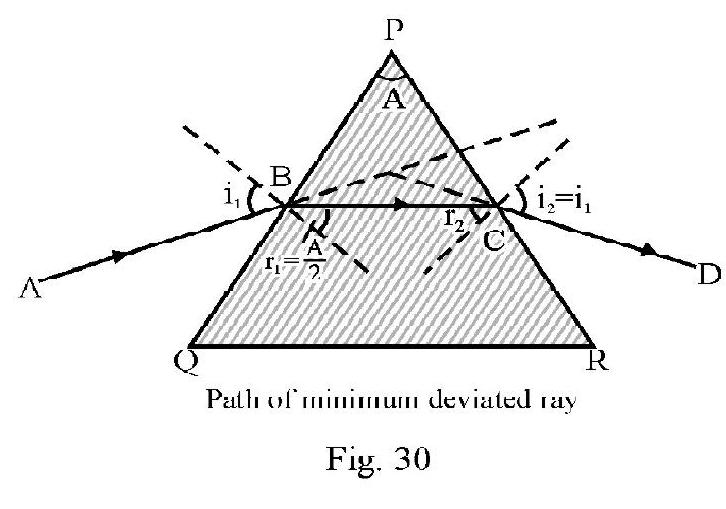
For a small angled prism; and are small. Taking ; aligned (6) reduces to
or
DISPERSION OF LIGHT
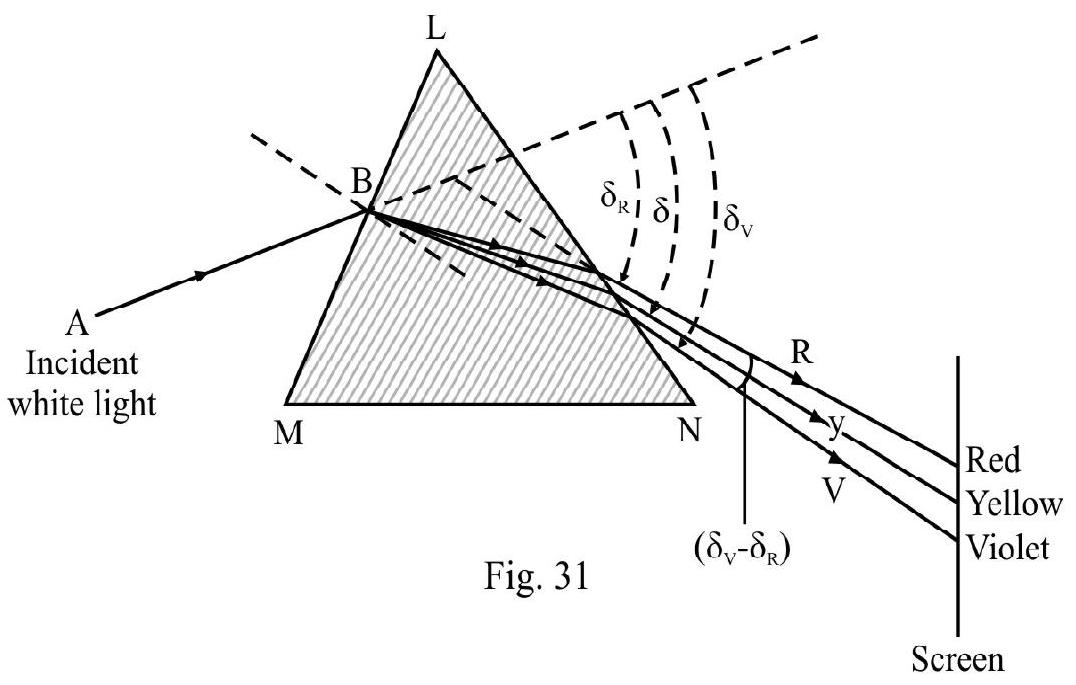
Figure- 31 shows an incident white ray of light, on a prism LMN. In passing through the prism the light breaks up into its constituent colours; VIBGYOR. This is known as dispersion of light. In Figure- 31; and are the angle of deviation for violet; yellow and red colour respectively. is known as angle of mean deviation. Also and , is known as angular dispersion. On the screen we see each constituent colour seperately. We say a spectrum of incident white light is produced on screen.
Cause of Dispersion of Light
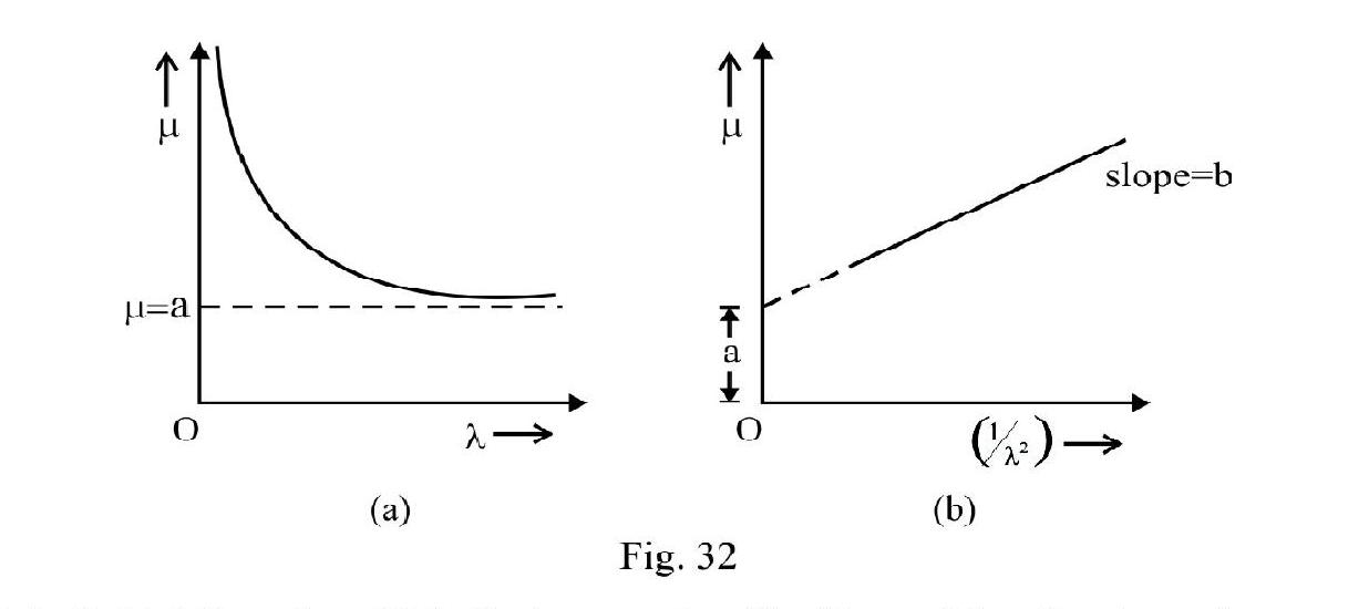
The dispersion of a polychromatic (i.e. white) light due to refraction in a medium occurs due to the variation of refractive index of the material with the wave length of the light. According to Cauchy
where and are constants and is wave length of light. This is known as CAUCHY’S RELATION. According to Equation (8) decreases as increases. For and for . The variation of with is shown graphically in Figure- 32 (a) and Figure- 32 (b) is graph of vs . This is a straight line with slope and intercept on axis equal to .
For incident white light AB on face LM of prism; angle of incidence for all colours is same. Since is different for different colours angle of refraction ( ) is different for different colour. Therefore different colours follow different paths and emerge out of prism in different directions. This is dispersion.
For white light we know that and . Therefore and . For small angled prisms, angle of deviation A therefore violet colour undergoes maximum deviation and deviation is minimum for red. The angle, ; between violet and red, is the angular dispersion produced by the prism, i.e.
Angular dispersion
Dispersive Power
The dispersive power, , of a refracting medium is angular dispersion per unit mean deviation; i.e.
For small angled prism, is a constant for a given medium. Let be the refracting angle of a small angled prism then
Mean deviation
Angular dispersion
The dispersive power
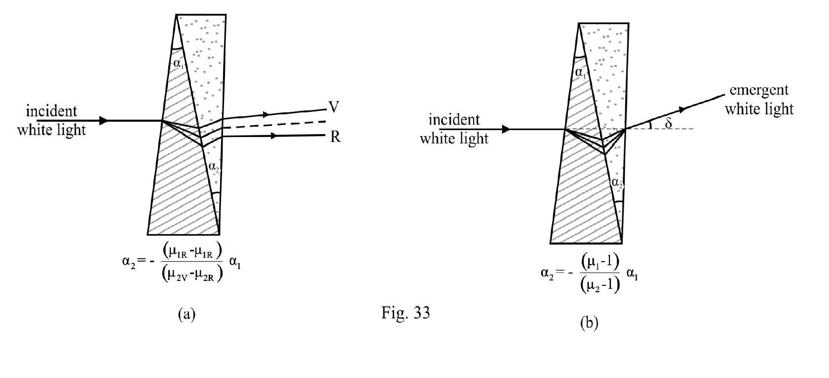
Combination of two small angled prisms
Consider two small angled prisms of angles and having dispersive power and respectively. Let and be the refractive index of prism 1 for violet; red and yellow (mean) colour. The corresponding quantities for prism 2 are and . Then
Let and be the angle of deviation of violet, red and mean colour for prism 1. Corresponding quantities for prism 2 are and respectively. For the combination of the two prisms
By choosing and properly we can have an arrangment causing
(i) Dispersion without deviation, i.e.;
and (ii) Deviation without dispersion, i.e.; and
The two arrangements are shown in Figure- 33 (a) & (b) respectively.
Example-15:
A rectangular glass slab of refractive index is immersed in water of refractive index . A ray of light is incident at surface of the slab as shown in Figure- 34. What is maximum value of angle of incidence on such that the ray imerges out only from the surface ?
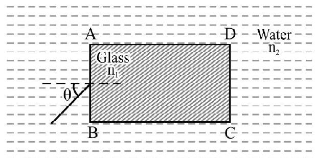
Figure- 34
Show Answer
Solution:
In Figure-35 is incident ray inside medium of refractive index . QR is refracted ray inside slab . Let be angle of refraction. From Snell’s law
The ray is incident on face at angle . It will not emerge out from if it undergoes total internal reflection at . This will be so it
where is critical angle of incidence from glass to water . We know
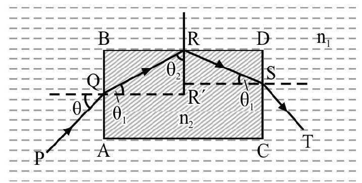
Figure- 35
Also from ‘;
For T.I.R to occur on face BD;
From equation (1); we have
Example-16:
is a right angled issoceless prism of a material of . A plane of refrative index is cemented to diagonal face is an incident ray. The refracted ray passes undeviated through the diagonal face . What is i?

Show Answer
Solution:

is incident ray on face . The refracted ray undergoes no deviation on diagonal face if its incident normally on as shown in Figure- 37. From Figure- angle of refraction on face . From Snell’s law
Example-17:
A ray of light is incident at an angle of one face of a prism of angle . The ray emerging out of the prism makes an angle of with incident ray. Show that the emergent ray is perpendicular to the face through which it emerges and calculate the refractive index of the material of prism.
Show Answer
Solution:
Let and be the angle of incidence and angle of emergence. is the refracting angle of prism. The angle of deviation is
Given and
or
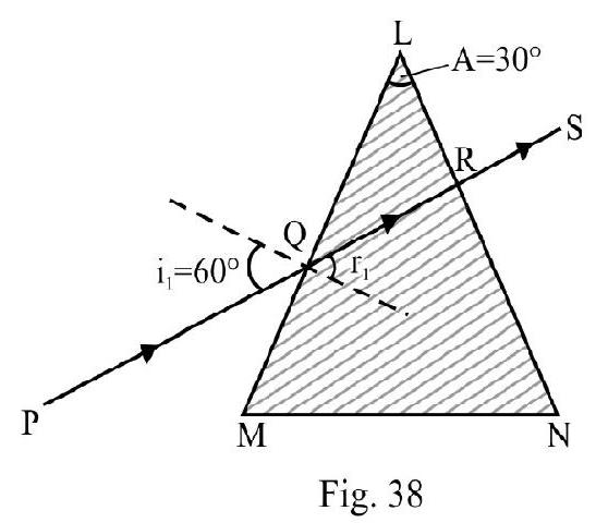
Since angle of emergence is zero; the light is incident normally on the face LN of prism as shown in Figure- 38. The angle of incidence inside prism at point .
Also,
or
Applying Snell’s law at point Q
Example-18:
Monochromatic light is incident on a glass prism of angle . The refractive index of the material of prism is .A ray is incident on one face at angle of incidence as shown in Figure- 39. Show that light will be transmitted through face ; if
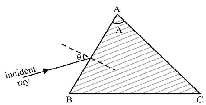
Figure- 39
Show Answer
Solution:
In Figure- is incident ray on face . Let be angle of refraction. From Snell’s law
Let be angle of incidence for ray on face of prism. The ray will emerge out of face if
where is critical angle of incidence inside glass. Also
From Figure- 40; we have
or
From equation (2), (3) and (4) we have
or
or
or
Example-19:
A right angled prism of refractive index is placed inside a rectangular block of refractive index , which is surrounded by a medium of refractive index as shown in Figure- 41. An incident ray enters the rectangular block at normal incidence. Four possible paths (1) (2) (3) and (4) are shown. In each case what is relation between and ?
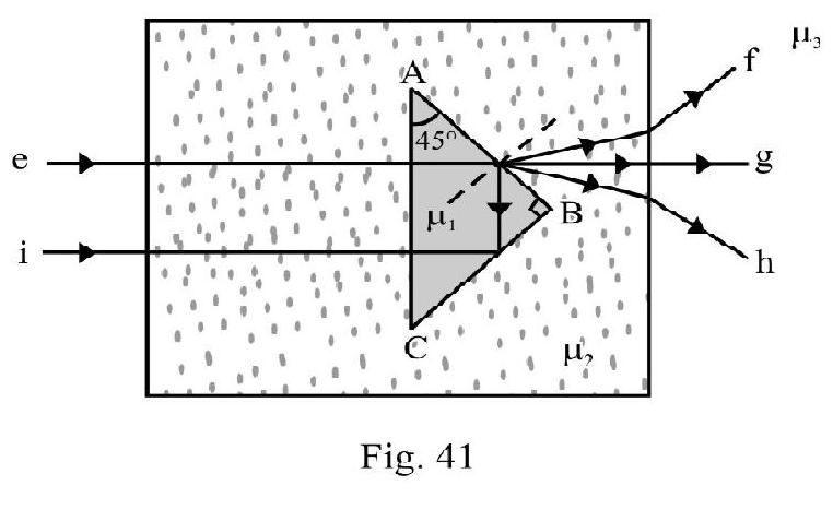
(I.I.T 2013; Adv)
Show Answer
Solution:
Case : The incident ray ’ ’ emerges out as ’ ‘. Total internal reflection occurs at face AB of prism; therefore . The critical angle of incidence from to is less than ie., .
or
Also,
From equation (1) and (2)
Case-II : The ray incident on emerges out and bends towards normal, i.e. . This ray incident on face of slab emerges out and bends away from normal; i.e. . Therefore
Case-III : The ray incident on face of prism as well as the face of rectangular slab emerges out straight i.e. there is no deviation. Therefore,
Case-IV: The incident ray ’e’emergs out as ray ’ ‘; on face of prism the ray undergoes refraction and moves away from normal; therefore
or
For the ray incident on slab; the refracted ray bends away from normal; therefore . Therefore
Example-20:
A ray of light is incident at grazing angle of incidence on one face of a prism of refracting angle A and refractive index . Show that angle of emergence is
Show Answer
Solution:
Figure- 42 shows incident ray grazing face of prism . The angle of incidence at point is . Let be the angle of refraction inside prism. Let be the critical angle of incidence from prism to air. Obviously . Also
Let be angle of imergence at point from face of prism. Applying Snell’s law at R
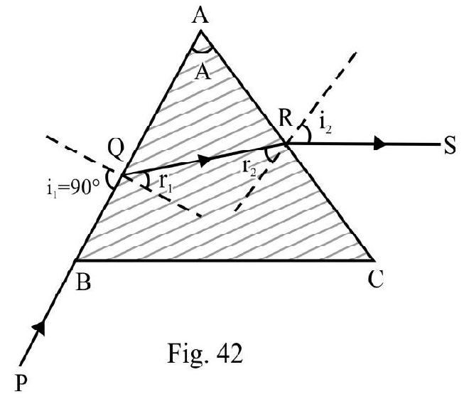
We also know that . Therefore
Example-21:
A prism of refractive index and another prism of refractive index are stuck together with a glue as shown in Figure- 43 . The angles of the prisms are shown in Figure- 43 . and depend on the wave length of light according to the relation
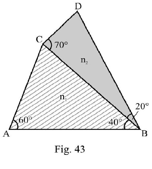
and
where is in .
(a) Calculate the wave length for which rays incident at any angle on the interface BC pass without any bending at that interface.
(b) For light of wave length find the angle of incidence on the face such that the deviation produced by the combination is minimum.
(I.I.T 1998)
Show Answer
Solution:
(a) There will be no deviation at face for any angle of incidence if . Therefore
or
(b) For ; the given arrangement is a part of a prism of angle . Let be angle of incidence of ray on face undergoing minimum deviation. For minimum deviated ray
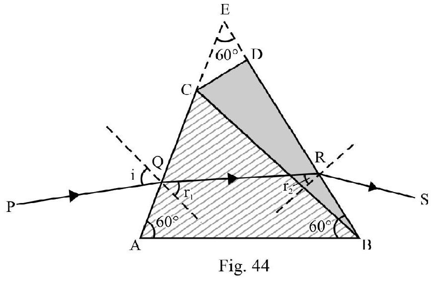
Applying Snell’s law at point Q; we have
Also,
From equation (2) and (3) we have
Example-22:
A crown glass prism has a refracting angle of . A white ray of light is incident on one face at an angle of . What is
(1) mean deviation
and
(2) angular dispersion?
Given and .
Show Answer
Solution:
For RED incident ray
Let be angle of refraction at the first face of prism. Given and . From Snell’s law
Let be angle of incidence on second face of prism. We know
Let be the angle of emergence. Applying Snell’s law
or
Let be angle of deviation for red colour. Then
For Violet Colour
Proceeding exactly in the same way as above, we have
Also, and
or
The mean deviation
The angular dispersion
REFRACTION AT A SPHERICAL SURFACE
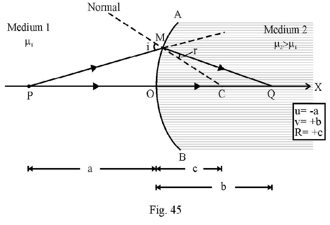
Figure- 45 shows a convex surface AOB seprating two media of refractive index and and . C is the center of curvature of spherical surface. is a point object on principal axis at a distance . The radius of spherical surface. Medium 1 of refractive index is the object space. The refracted ray goes into medium 2 of refractive index . This is the image space Figure- 45 shows incident ray PM and refracted ray MQ. Since we have ; the refracted ray bends towards normal. The refracted ray meets principal axis at . We say is real image of real object . Using co-ordinate convention of signs.
The object position
The image position
The radius of curvature
It can be shown that
aligned (1) is ‘refraction formula for a spherical surface’. The same formula is valid for a concave spherical surface. Figure- 46 shows refraction at a concave surface. Note the image formed is virtual.
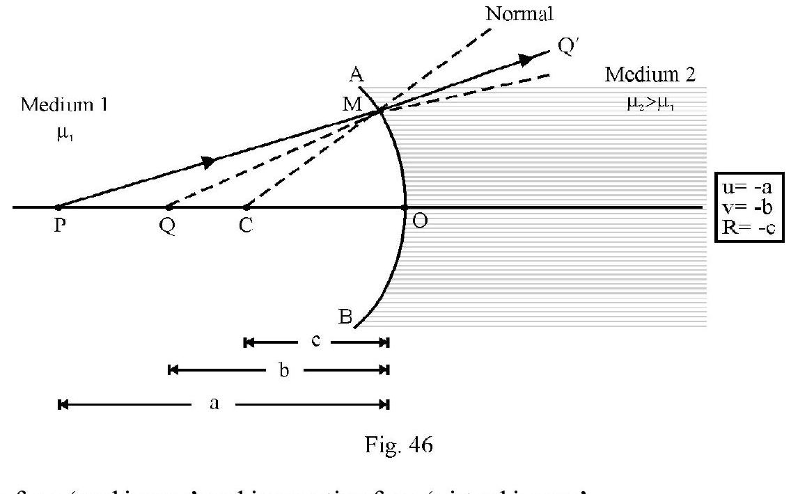
Note is positive for a ‘real image’ and is negative for a ‘virtual image’.
Principal Focus; Focal Length and Focal Plane
Let a parallel beam; parallel to principal axis be incident in medium 1. The refracted rays.
(i) meets principal axis at a point for a convex surface
(ii) appear to meet principal axis at a point for a concave surface
as shown in Figure- 47 (a) and (b); if is known as second principal focus. Its position given the second principal focal length . Expressed mathematically,
From equation (1), we have
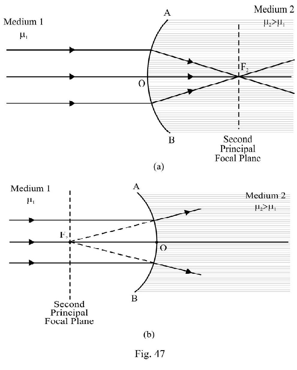
For ; the convex surface behaves as a converging surface and the concave surface as a diverging surface. However it ; the convex surface behaves as a diverging surface and concave surface as converging surface. The converging or diverging nature of a surface depends on value of and .
A plane perpendicular to principal axis through point is the second principal focal plane. A parallel incident beam inclined to principal axis; after refraction meets or appears to meet at a point on the second principal focal plane.
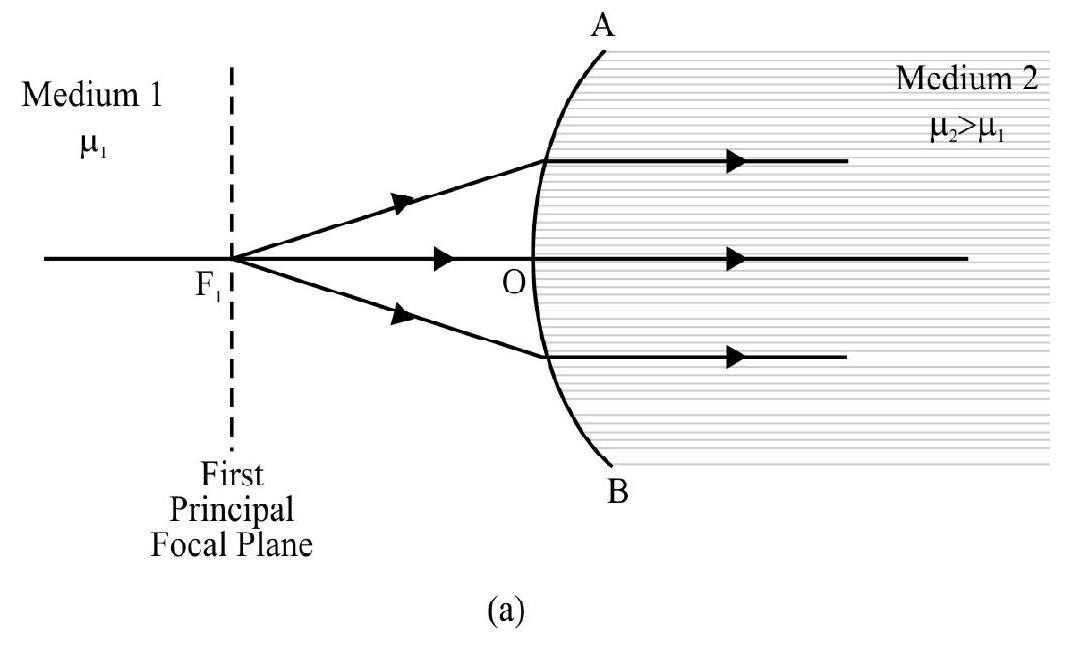
The ‘First Principal Focus’; Focal Length and Focal Plane.
Let , then for a
(1) Convex Surface: is a point on principal axis where if an object is placed the refracted rays are parallel to principal axis as shown in Figure- 48 (a).
(2) Concave Surface: is a point on principal axis where if an object is imagined to be placed (i.e. virtual object) the refracted rays are parallel to principle axis as shown in Figure- 48 (b).
is known as the ‘first principal focus’. Position of gives first principal focal length . Expressed mathematically
From equation (1) we have
Note . Since . In general, the two focii are not equidistant from the spherical surface.
A plane perpendicular to principal axis through is the “first principal focal plane”.
By convention; the focal length of a spherical surface is the position of ; i.e. . From equation (2);
In terms of focal length; ; the refraction formula expressed in aligned (1) can be rewritten as
The Power of a Spherical Surface
The reciprocal of focal length f of the refracting surface expressed in meter; is the power of the surface. SI unit of P is diopter. Expressed mathematically
For is a positive number for a convex refracting surface and is a negative number of a concave surface. However sign of P changes for both surfaces it .
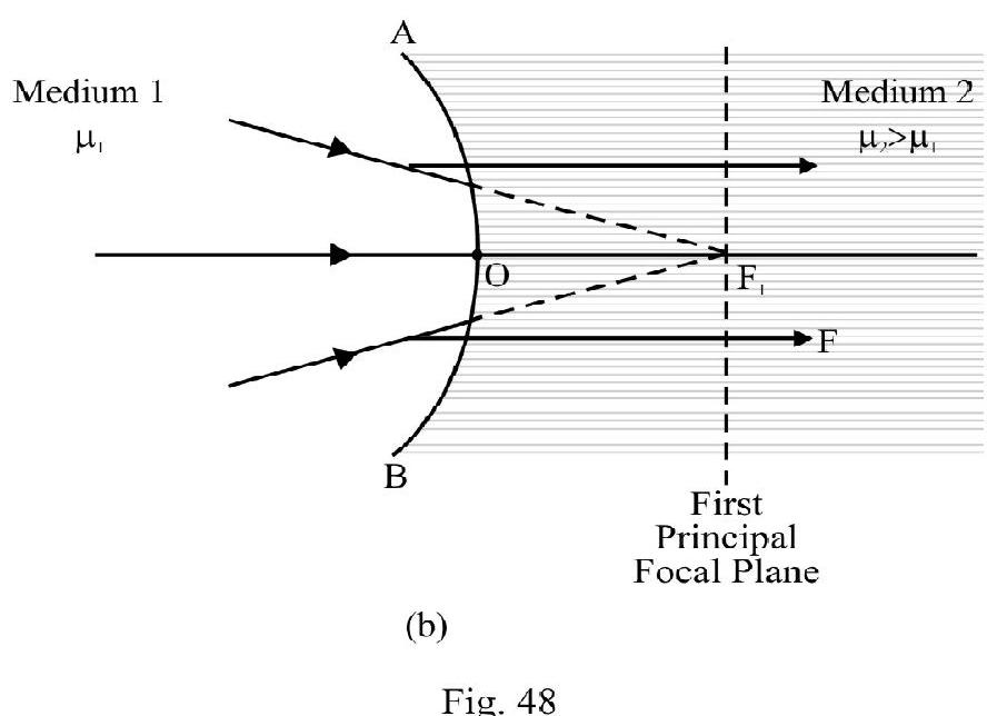
Refraction at Spherical Surface for an Object of Finite Size
Figure- 50 shows an object placed in medium ’ is the real, inverted image formed in medium 2. is length of image formed. In terms of co-ordinate convention of sign
The transverse magnification . It can be shown that
Where reduced image posion and reduced object position.
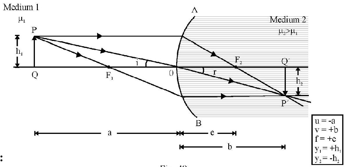
Figure- 49
Important Note:
The following table gives the sign of , , fetc. for refraction at a spherical surface.
| 1. |
(i) Convex Surface
(ii) Concave Surface |
f is + ve for
is - ve for
f is - ve for
is + ve for |
| 2 |
Objecct |
is -ve for a real object
is for a virtual object |
| 3. |
Image |
is for a real image
is for a virtual image |
| 4. |
Magnification |
is + ve for erect image
is for inverted image
, enlarged image
, diminished image |
Example-23:
A point object is placed at a point mid-way between the center and surface of a glass sphere of radius refractive index 1.5 . What is distance of the image as seen from air outside from the side of the sphere to which object is nearer?
Show Answer
Solution:
In Figure- is the point object inside glass. Observer is to the right of point . We have
From refraction formula at a spherical surface
we have
Since is negative the image is virtual, at a distance of from the center of sphere.
Example-24:
A parallel beam of light travelling in water is refracted by a spherical air bubble of radius inside water. Find the position of image due to refraction at both surfaces of bubble.
(I.I.T 1992)
Show Answer
Solution:
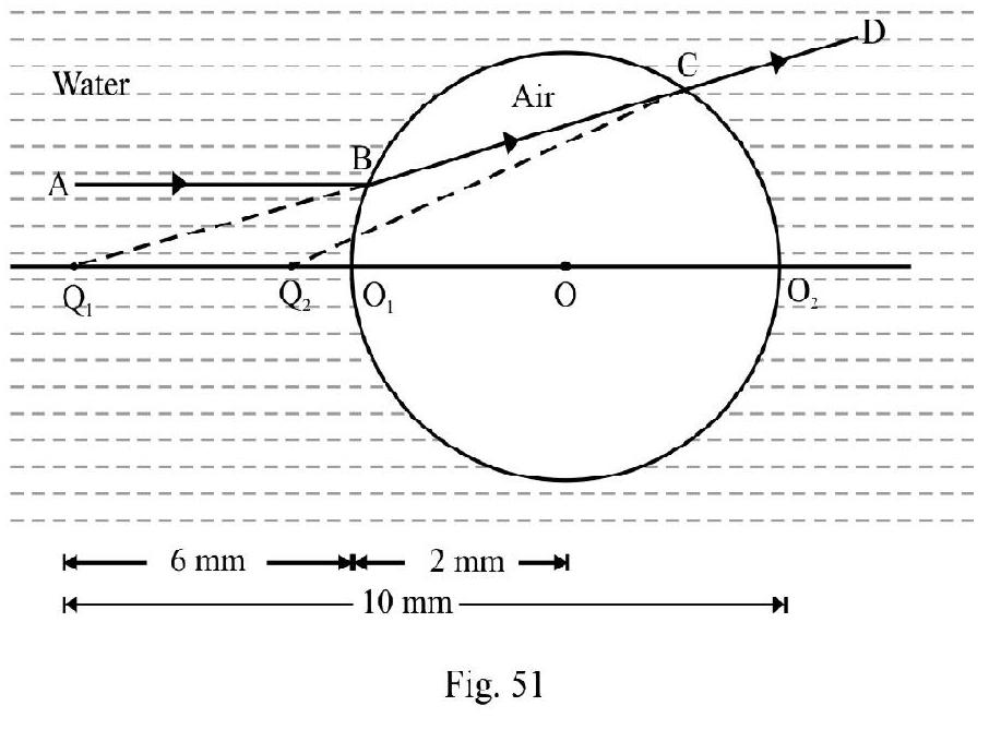
For refraction at first surface
Using refraction formula we have
For refraction at second surface acts as object. The final image is as shown in Figure- 52. For second surface
Using refraction formula; we have
Since is negative the final image is VIRTUAL at a distance of from .
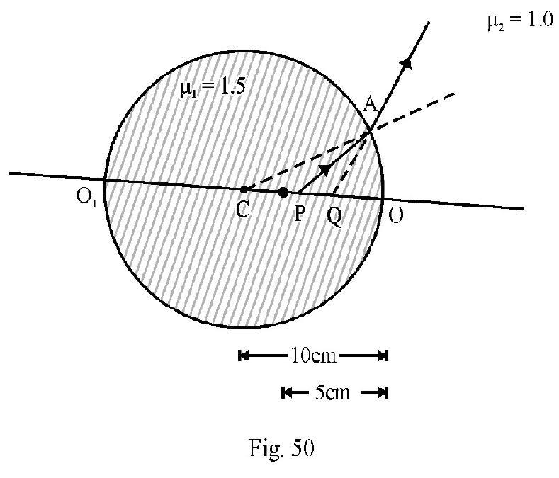
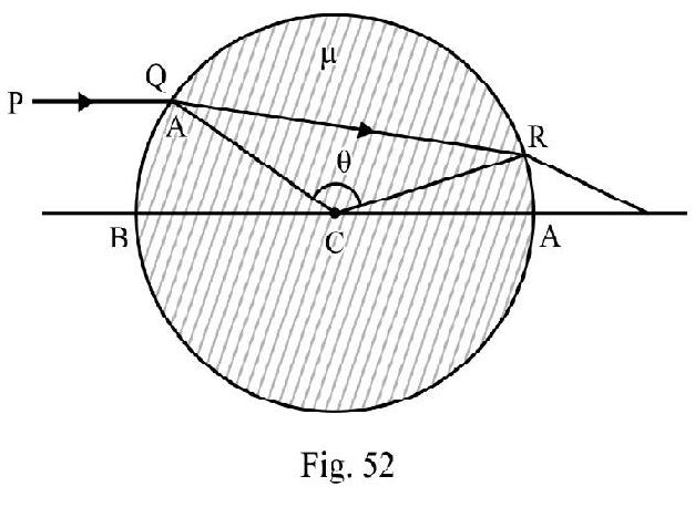
Example-25:
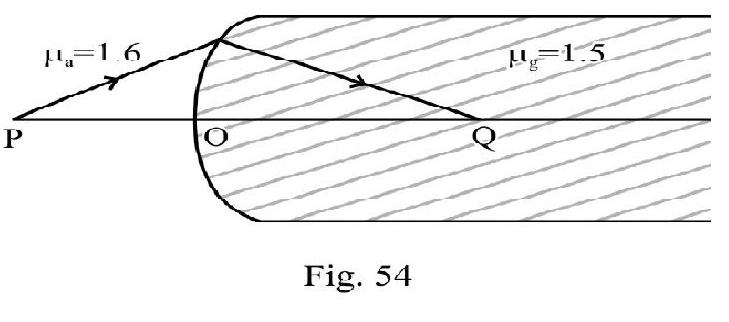
is an incident ray on a sphere of radius and refractive index . It passes through the edge and of two radii inclined to one another at an angle of . The net deviation the ray undergoes in passing through sphere is . What is ?
Show Answer
Solution:
Figure- 54 shows the refraction of ray through the sphere. Let and be angle of incidence and refraction at . From triangle QCR.
The total deviation ; is
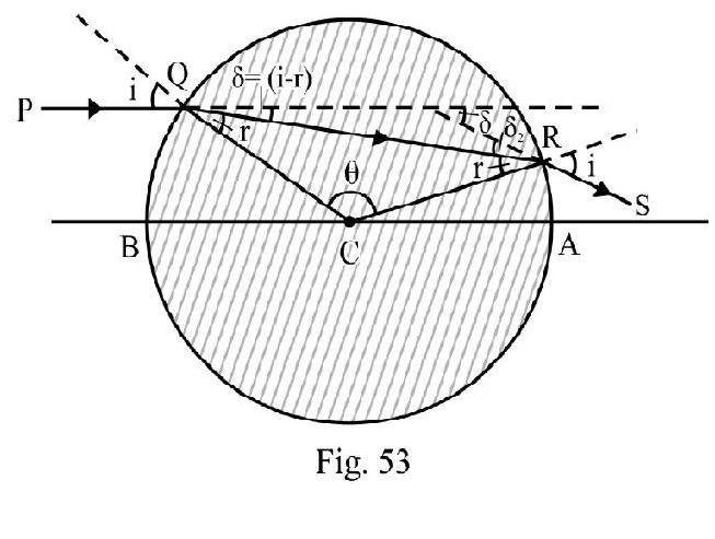
From equation (1) and (2) we have
From equation (1); we have
Applying Snell’s law at point Q
Example-26:
A spherical surfaces of radius of curvature seperates air from glass . The centre of curvature is in glass. A point object placed in air is found to have a real image in the glass. The line cuts the surface at a point and . What is distance ?
Show Answer
Solution:
Let
We have the relation
or
Example-27:
A convex surface of radius seperates water and glass ( . An object of length is placed perpendicular to principal axis, in water; at a distance of . What is position, natural and length of image formed?
Show Answer
Solution:
Given ?
From refraction formula
We have
Negative sign of indicates that image formed is virtual at a distance of from the convex surface. The magnification, ;
The positive sign of m indcates erect image. The length, , of image is
The image formed is virtual, erect at a distance of and has a length of
THIN LENSES
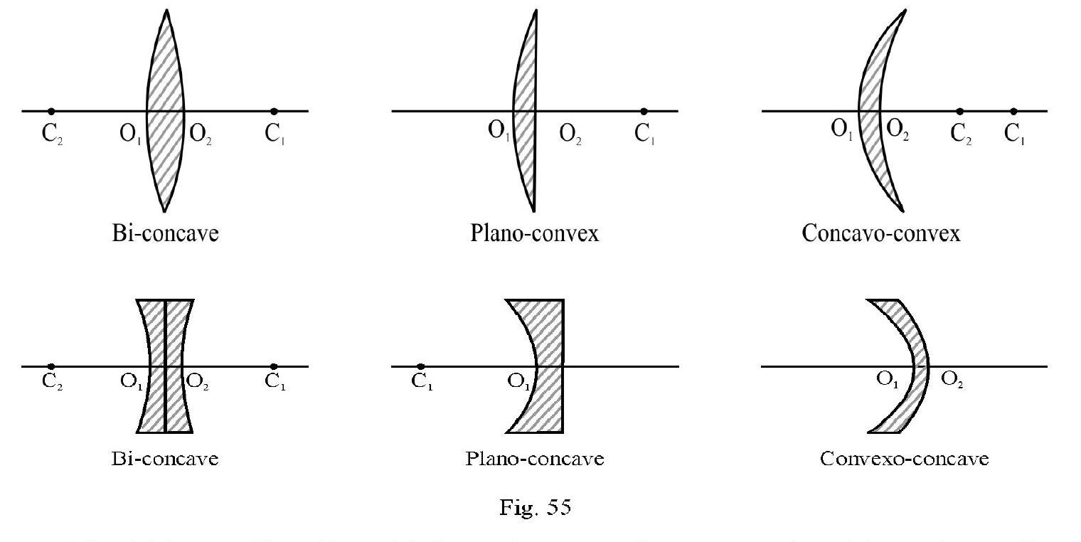
A lens is a refracting medium bound by two spherical surfaces. There are two type of lenses (i) convex lenses and (ii) concave lens. The three variation of each type as shown in Figure- 56.
The thickness of lens. For a thin lense is very small as compared to object or image distance or focal length of lens.
Refraction at a Thin Lens
Figure- 57 shows a convex lens of a material of refractive index . The media on the two sides of the lens have refractive index and respectively. is a point object placed on principal axis in medium 1 known as object space. PA is incident ray on the first surface of lens. Had there been only one surface the refracted ray would have met principal axis at . For refraction at first surface
From refraction formula at a spherical surface
The refracted ray from first surface meets second surface of lens at and the emergent ray meets principal axis at Q. Q is final image formed by lens due to refraction at both surfaces. For refraction at second surface of lens acts as a virtual object forming real image . For refraction at second surface
Adding aligned (1) and (2) we have
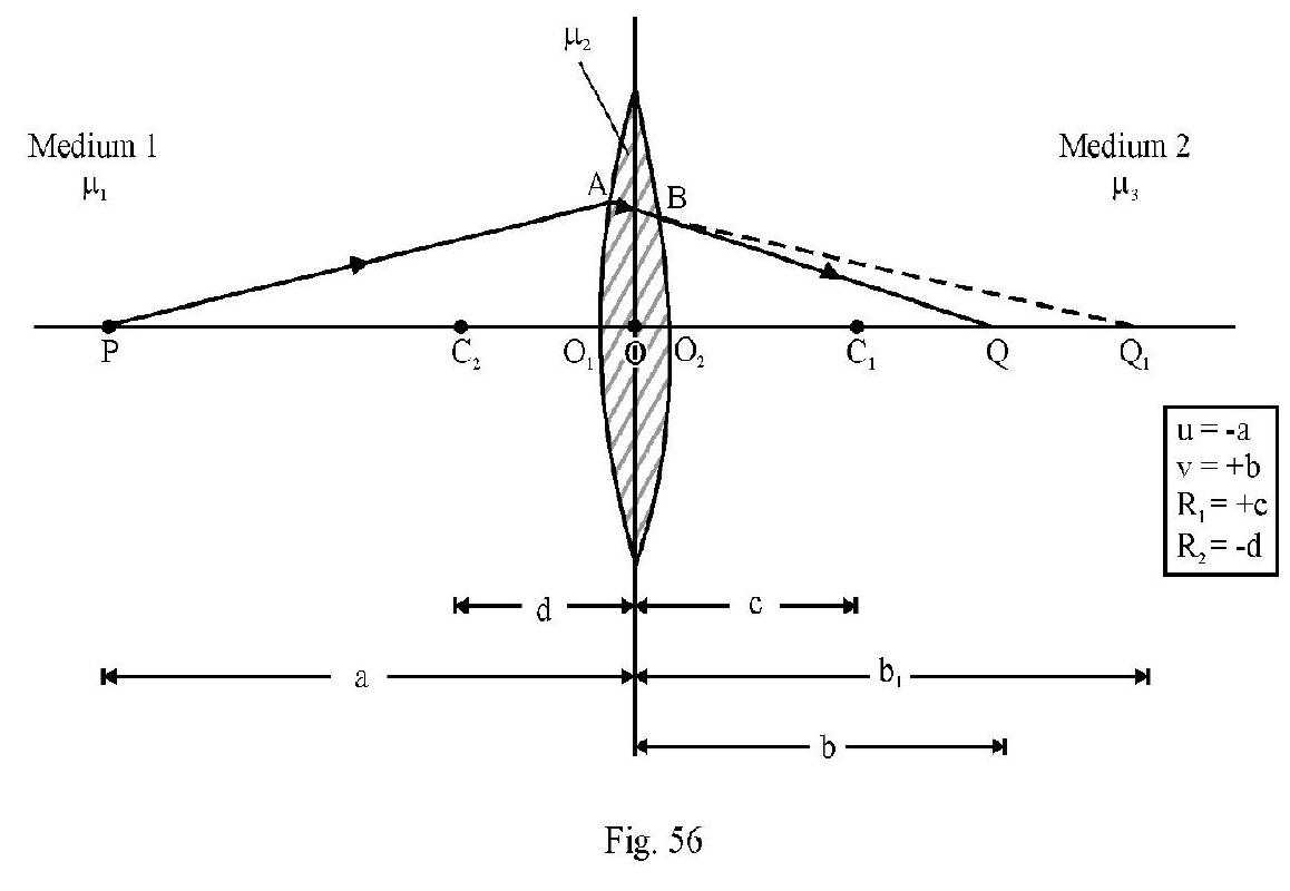
Let and denote the position of object and final image . In terms of co-ordinate convention of signs.
We rewrite aligned (3) as
aligned (4) in the refraction formula for a thin lens. Commonly the media on both sides of lens is same i.e. aligned (4) reduces to
This is refraction formula for a thin lens.
Focii and Focal Length of a Lens
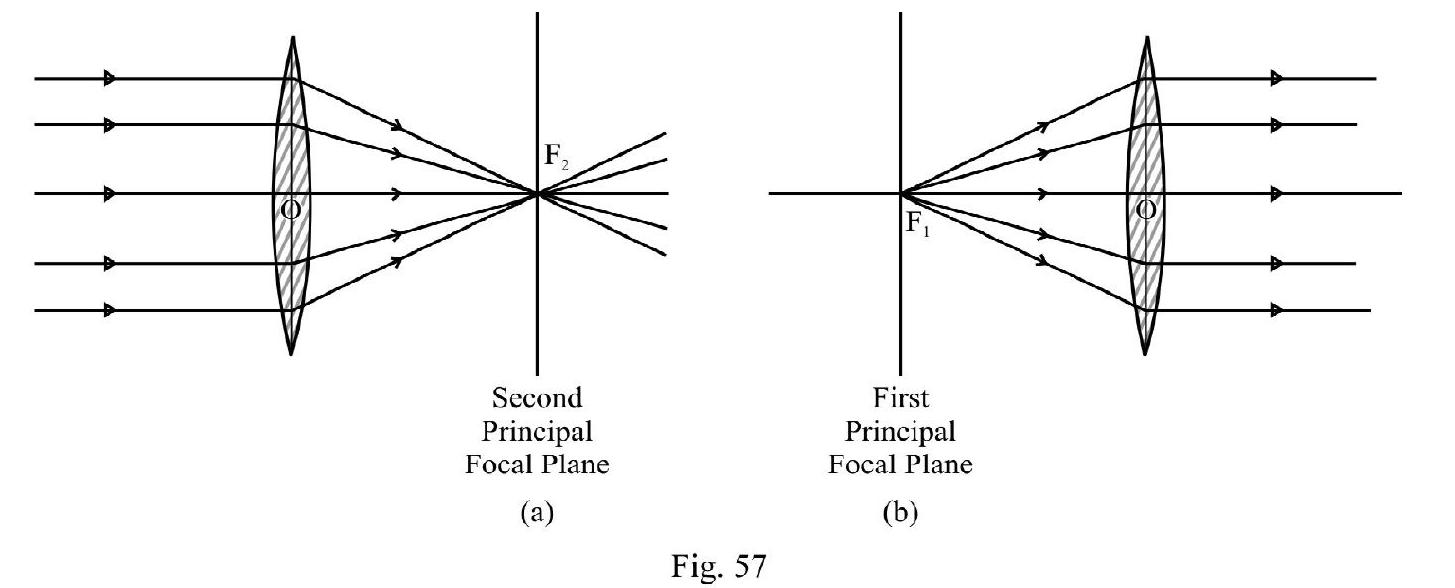
(1) Second Principal Focus,
Consider a parallel beam, parallel to principal axis, incident on lens. The refracted rays meets or appears to meet principal axis at . is the second principal focus of lens. Position of gives
second principal focal length . Expressed mathematically;
From equation (4) we have
(2) First Principal Focus,
is a point on principle axis where if an object is placed or appears to be placed the refracted rays are parallel to principal axis. is known as the first principal focus. Position of gives the first principal focal length of the lens. In language of mathematics
From equation (4) we have
Note in general In words; in general the two focii are not equidistant from lens.
The focal length of lens is the position of second principal focus i.e. . In terms of focal length, ; aligned (4) is rewritten as
This is the genral refraction formula for a thin lens. However commonly ;aligned (6) and (8) reduces to
aligned (9) is known as Lens Maker’s Formula For a lens placed in air, i.e. and the lens maker’s formula reduces to
Nature of a Convex and a Concave Lens
Case-I : Convex Lens
For a convex lens; and d. From equation (9);
(a) Let , i.e. refractive index of lens is more than refractive index of medium in which lens is placed. From equation (11), f is a +ve number. The incident parallel beam on lens, after refraction actually meets principal axis at as shown Figure- 58 (a). Under these conditions convex lens behaves as a converging lens. Figure- 58 (b) shows position of since ; i.e. the two focci are equidistance from lens if medium on both sides of lens is same.
(b) Let . From equation (11) fis a negative number! This means a convex lens behaves as a diverging lens. The converging or diverging nature of lens depends the nature of medium (i.e. ) in which lens is placed.
Case-II : Concave Lens
In accordance with the sign convention, for a concave lens . From equation (9); the focal length, ; of lens is
(a) Let ; fis a negative number. This means a parallel beam, incident on a concave lens appears to meet principal axis at as shown in Figure- 58 (a). The concave lens behaves as a diverging lens. Figure- 58 (b) shows position of .
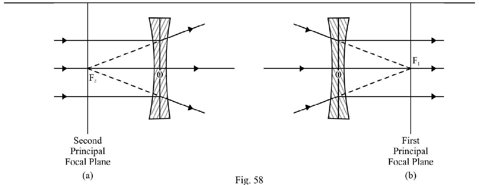
(b) Let ; fis a positive number. The concave lens new behaves as converging lens!
The Power of a Lens
The power, , of a lens describes the ability of the lens to bend incident rays towards or away from principal axis. It is the reciprocal of focal length expressed in meter. S.I unit of power is dropter.
A positive value of P indicates converging behaviour and a negative value the diverging behaviour of the lens.
Object of Finite Size
Case-I : Convex Lens
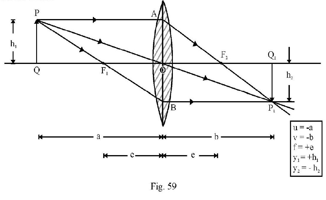
Figure- 60 shows an object placed perpendicular to principal axis at a distance a from the lens. is the real; inverted image formed. The transverse magnification, ; is
It can be shown that
Let be the distance of the object from , and the distance of image from . Then
This is Newton’s Formula
The following table gives the nature, position and magnification of a real object as it moves from infinity, towards convex lens.
| S.No. |
Position of Object |
Image |
|
|
|
Position |
Nature |
| 1. |
At infinity |
Focus |
real, inverted, highly diminished |
| 2. |
In between and |
In between and 2F |
real, inverted, diminished |
| 3. |
At |
At 2F |
real, inverted, same size as object |
| 4. |
In between and |
Beyond |
real, inverted, enlarged |
| 5. |
At |
At infinity |
real, inverted, highly enlarged |
| 6. |
In between and |
Beyond lens |
virtual, erect and enlarged |
Case-II : Concave Lens
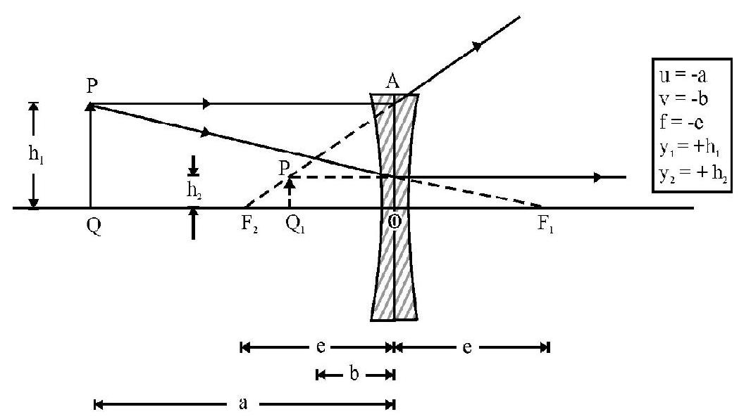
Figure- 60
Figure- 61 shows the virtual, erect and dimished image of a real object PQ. A concave lens forms a virtual, erect; dimished image of a real object irrespective of the position of object.
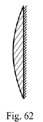
Figure- 62 shows two co-axial thin lenses and of focal length and in contact. Treating the system as a thin lens; the equivalent focal length; ; of the combination is
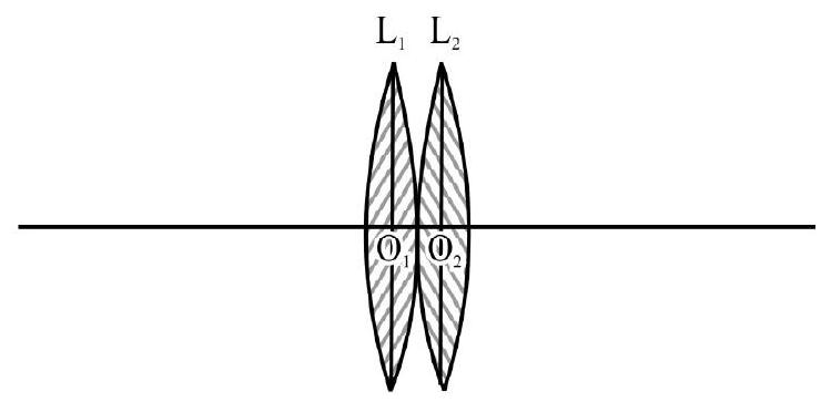
Figure- 61
In terms of power, the above equations is rewritten as
For a number of co-axial thin lenses, in contact, the treating the combinations as a thin lens; we have
When one surface of a thin lens is silvered; the rays are reflected back from the silvered surface. The set up behaves like a spherical mirror. The ’thumb rule’ for the equivalent focal length fof the spherical mirror is
is the focal length of the lens or mirror; to be repeated as many times as reflection or refraction respectively is repeated.
A plano-convex lens silvered at its plane surface as shown in Figure- 63; there are two refractions and one reflection; therefore
is focal length of plano convex lens. Obviously; focal length of mirror
For plano-convex lens silvered at its curved surface, as shown in Figure- 63. We have
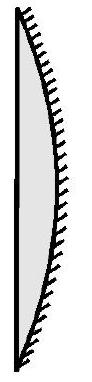
Figure- 63
OPTICAL INSTRUMENTS
Microscope is an optical instrument used to forn an enlarged image of a nearby small sized object.
A simple microscope is a short focal length, ; convex lens. The object to be magnified is placed within focus and optical center of lens. The image formed is virtual; erect and enlarged.
The Compound Microscope
A compound microscope consists of two short focal length co-axial convex lenses a finite distance apart. The object to be magnified is placed in front of lens of focal length and is close to but outside the focus . The -lens forms a real; inverted and enlarged image. This image acts as object for the E-lens of focal length . The final image formed is inverted with respect to the object.
and denote magnification due to - and - lens respectively. For a microscope forming final image at distance of distinct vision;
The length of microscope Distance between and lens
; is distance of image formed by lens from lens.
If microscope is so adjusted that final image is at infinity; the M.P is slightly less than what is given by
aligned (1) and the length is more than given by aligned (2).
The Telescope
Telescope is an optical instrument used to form an enlarged image of a far offlarge sized object.
An astronomical telescope consists of a large aperture, large focal length lens. The eye-lens ( lens) is a co-axial convex lens of small focal length . For an astronomical telescope, in normal, adjustment
Length of telescope Distance between and Lens
Example-28:
An equi-convex lens of radius has a refractive index of 1.5 . The difference in the focal length of the lens when surrounded by water and air is
(a)
(b)
(c)
(d)
Show Answer
Solution:
When lens is immersed completely in water
The difference in focal length oflens in water and air is
Hence option (a) is correct
Example-29:
A hollow double concave lens is made of very thin transparent material. It can be filled with air or either of two liquids and having refractive indices and respectively . The lens will diverge a parallel beam of light if it is filled will
(a) air and placed in air
(b) air and immersed in
(c) and immersed in
(d) and immersed in
Show Answer
Solution:
Let denote the refractive index oflens and the refractive index of medium. From lens maker’s formula
For a double concave lens is negative and is positive. Hence will be negative number. The focal length fof the lens has to be negative if it has to behave as a diverging lens. For this to happen should be positive implying that . Also it is given that and also . considering all this information lens should be filled with and immersed in .
Hence option (d) is correct.
Example-30:
A square of side is placed on principal axis of a lens at a distance of . The lens projects image of area on a screen.
(a) What is distance between object and screen?
(b) What is nature and power of lens?
Show Answer
Solution:
Since the area of image is 16 times that of object; the magnitude of linear magnification . The image is projected on a screen; therefore it is a real image and therefore inverted, i.e.
Also ; therefore
or
The distance of screen from lens is . Obviously distance between screen and object . Let be the focal length of lens. From refraction formula
The positive sign of indicates convex lens. The power, , of lens is
Example-31:
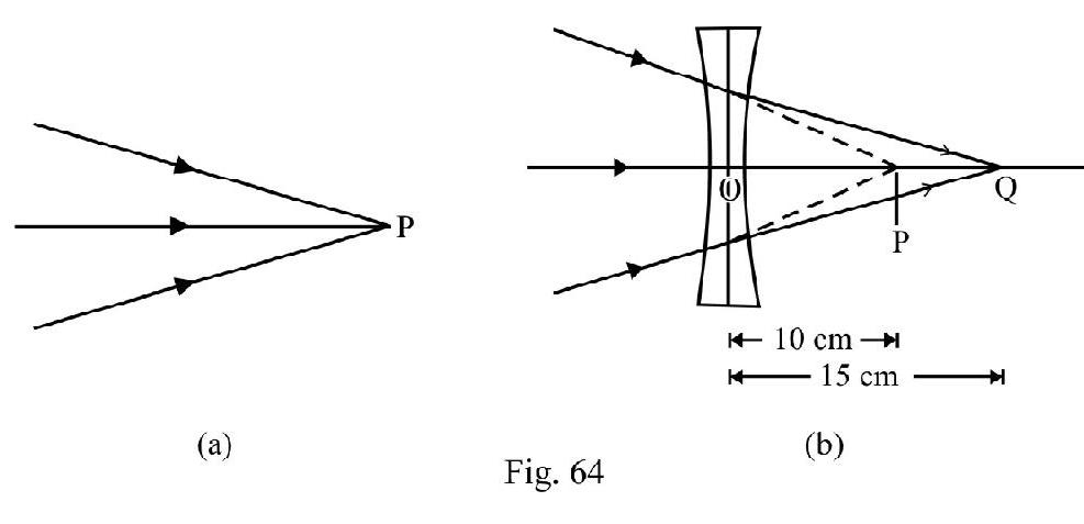
A beam of light converges towards a point as shown in Figure- 64(a). A concave lens is placed 10 in front of . The point where beam now converges moves away by of distance of lens from . What is focal length of the lens? If lens is made of a material of ; assuming that the two faces of lens have same radius of curvature; calculate the radius of convature of each surface of lens.
Show Answer
Solution:
Figure- 64 (a) shows the incident convergent beam. Figure- 64 (b) shows concave lens placed in front ofP. Now acts as a virtual object forming real image . Therefore
From refraction formula; for a lens
Let be magnitude of radius of curvature of each surface of lens. According to co-ordinate convention. . From lens maker’s formula
Example-32:
A concave lens has a focal length . An object is placed at a distance times the focal length of the lens. What is the magnification?
Show Answer
Solution:
Let e be the magnitude of focal length of concave lens. The object is at a distance e in front of lens.
Therefore e.
Let be the position of image formed. Using lens formula we have
The transverse magnification
Since is positive, image formed is erect. Also ; the image formed is diminished.
Example-33:
A short linear object of length lies along the axis of a concave mirror of focal length at a distance a from the pole of the mirror. The size of the image is approximately equal is
(a)
(b)
(c)
(d)
Show Answer
Solution:
In the mirror formula
f is a constant so we have on differentiating
is representing the size of the image and is size of obejct lying along the axis .
From the mirror formula we also have
From Equations (i) and (ii) we have
Size of the image
Hence option (d) is correct.
Example-34:
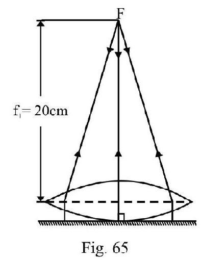
A thin equiconvex lens is placed on a horizontal plane mirror and a pin held above the lens. The system forms an image that coincides in position with the position of the pin. Now the space between the lens and mirror is filled will water and then to coincide the pin with will its own image, the pin has to be raised until its distance from the lens is . What is the radius of curvature of lens?
Show Answer
Solution:
The image of pin coincides with of pin if incident rays from pin after refraction through lens fall normally on plane mirror as shown in Figure- 65. Pin is position of focus of the lens.
Let the focal length of water lens be , then for the combination of the two lens, the equivalent focal length of the combination is . We have
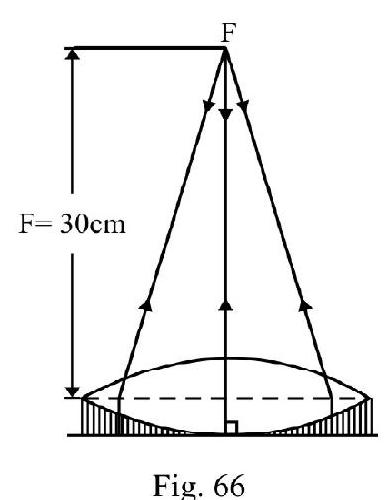
where is refractive index of water. For plano-convex water lens ; therefore
Example-35:
A lens having focal length and aperture of diameter forms an image of intensity . Aperture of diameter in central region of lens is covered by a black paper. Focal length of lens and intensity of image now are
(a) f and
(b) and
(c) f and
(d) and
Show Answer
Solution:
It is evident that by convering the aperature of diameter , focal length of lens does not change. However since the in this process the area is reduced to th of its earlier value, the intensity of the image will be reduced by .
Hence the focal length will remain fand new intensity of the image will be
Hence option (c) is correct.
Example-36:
The focal length of the objective and eye piece of a telescope is and respectively. The telescope is focussed for distinct vision on a scale away from the objective. The seperation between the objective and eye piece is
(a)
(b)
(c)
(d)
Show Answer
Solution:
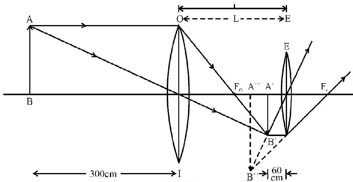
Figure- 67
As shown let be the position of the object and let ’ be the image formed by the objective lens.
Then
This image ’ serves as an object for eye piece. The distance between and the eye piece is
where is the seperation between the two lenses. The final image distance is from the eye piece. Now
Example-37:
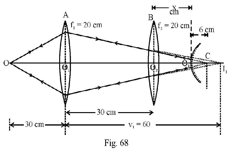
A convex lens of focal length is placed at a distance of to the right of an identical lens A. A point object is placed at a distance of to the left of A. A convex mirror of radius of curvature is to be placed on the common axis of the lens at a distance from lens B such that the final image formed by the arrangement coincides with the object. is
(a)
(b)
(c)
(d)
Show Answer
Solution:
For the lens
Figure- 68
Had there been no lens B lens A would have formed a real image of the object at shown as in Figure- 68. For the lens B, acts as a virtual object. Therefore
From lens formula we have
or
The refracted rays from lens B must fall normally on convex mirror so that rays retrace their path and the final image formed by system coincedes with object . This will be so if ray incident on convex mirror would have met at center of curvature C of mirror. Obviously from Figure- 68.
or
Example-38:
(a) A thin convex and concave lens of power and 2.5 D are placed co-axially in contact with one another. An object of length is placed in front of the combination. What is position and length of image formed?
(b) Keeping object and convex lens in position concave lens is moved away by . What is change in position and length of the image formed now as compared to their earlier values?
Show Answer
Solution:
The power of convex lens The power of concave lens
The power of the combination
The equivalent focal length of the combination
For the combination, given
The magnification
Length of image formed
Figure- 69 shows the arrangment when concave lens is moved away from the convex lens .
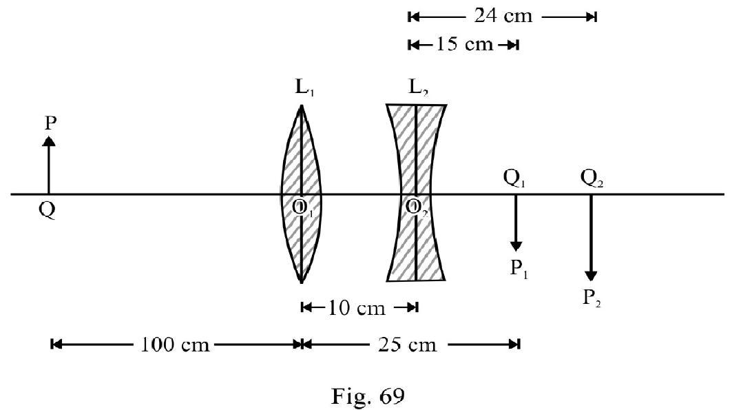
For Convex Lens
The magnification , due to convex lens is
The image formed by convex lens is real, inverted and diminished.
Length of image
For Concave Lens
acts as a virtual object for concave lens. Therefore
or
The final image is real at a distance of from . The magnification due to concave lens is
The image is erect with respect to i.e. inverted with respect to object .
The length of image
The change in position of image
The change in length of image
Example-39:
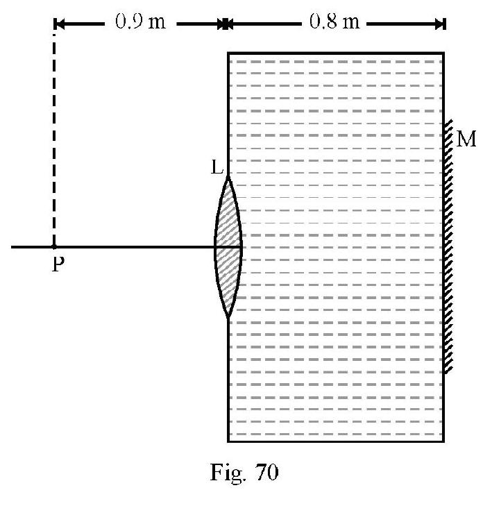
A thin equi-convex lens made of glass of refractive index and focal length in air is sealed into an opening in a tank filled with water . On the wall of tank opposite lens a mirror is placed as shown in Figure- 70. The distance between the lens and the mirror is . A small point object is placed on principal axis at a distance of from the lens. Find the position of the final image with respect to lens, due to the system.
Show Answer
Solution:
Let be the magnitude of radius of curvature of each surface of equiconvex lens of (given). Using lens maker’s formula
First image of P is formed due to refraction at lens L. Let and be refractive index of object space, lens material and image space respectively. and represent the object and image position. Then
For first refraction at lens L
Had there been only lens , the image of would have been real at a distance of from . However the refracted rays undergo reflection at mirror on the opposite wall. For mirror acts as a virtual object at a distance of from . The mirror forms a real image in front of acts as a real object in water and refraction again takes place at lens L. To apply refraction formula at , imagine diagram to be rotated by , so that incident ray on are moving from left to right, in accordance with sign convention. Now
?
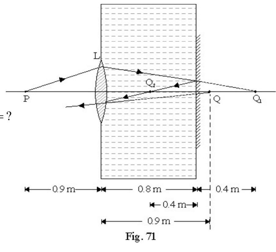
From equation (1), we have
Figure- 71
Negative sign of indicates that final image formed (Q)is virtual at a distance of from lens .
Figure- 73 shows the ray diagram for image formed by the system.
Example-40:
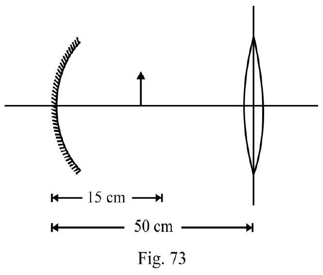
Consider a concave mirror and a convex lens (refractive index 1.5) of focal length each seperated by a distance of in air (refractive index ) as shown in Figure- 73. An object is placed at a distance of from the mirror. Its erect image formed by combination has a magnification .
When the set up in kept in a medium of refractive index the magnification becomes . What is ?
Show Answer
Solution:
Case-I : Arrangement in Air
(a) For Convave Mirror
(b) For Lens
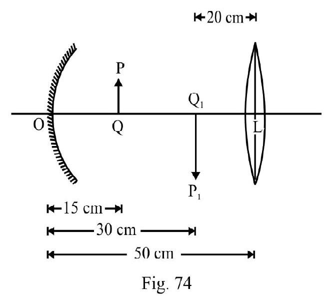
The image acts as object for lens. For lens
Case-II : Arrangement inside medium
For reflection at mirror there is no change. Let be focal length of convex lens inside medium.
For lens
or
Now,
Example-41:
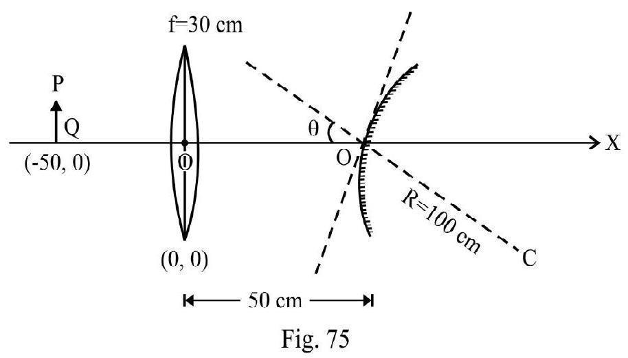
A small object is placed to the left of a thin convex lens of focal length . A convex spherical mirror of radius of curvature is placed to the right of the lens at a distance of . The mirror is tilted such that its axis make an angle of with axis of lens as shown in Figure- 75 If the origin of co-ordinate system is taken to be the center of the lens, the co-ordinates (in ) of the point ) at which is formed are:
(a)
(b)
(c)
(d)
(I.I.T Adv. 2016)
Show Answer
Solution:
For lens . From lens formula

Had there been only lens ; the image would have been at a distance as shown in Figure- 76. For mirror acts as a virtual object. The distance of point from mirror
.
Length of virtual object for mirror.
For mirror
From mirror formula, we have
or
Since is negative, the image formed is real. Distance
The magnification
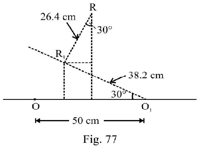
In the figure is final image of point . From Figure- 77 the -co-ordinate of point
From Figure- 77 the -co-ordinate of point
WAVE OPTICS
The study of wave optics involves the study of the phenomenon supporting wave nature of light. The basic phenomenon involved are:
(1) Interfernece
(2) Diffraction
and (3) Polarisation of light.
Wave and Wave-Front
The phenomenon of wave-motion involves the propagation of a disturbance in a medium. The particles of medium execute SHM about their respective mean positions. There is propagation of energy in the direction of wave motion. According to E.M theory light is electromagnetic waves of wave length range 4000-7500 A. This is the visible part of electromagnetic spectrum. In E.M waves the electric and magnetic fields executes SHM in mutually perpendicular direction. Both the directions are also perpendicular to the direction of wave motion.
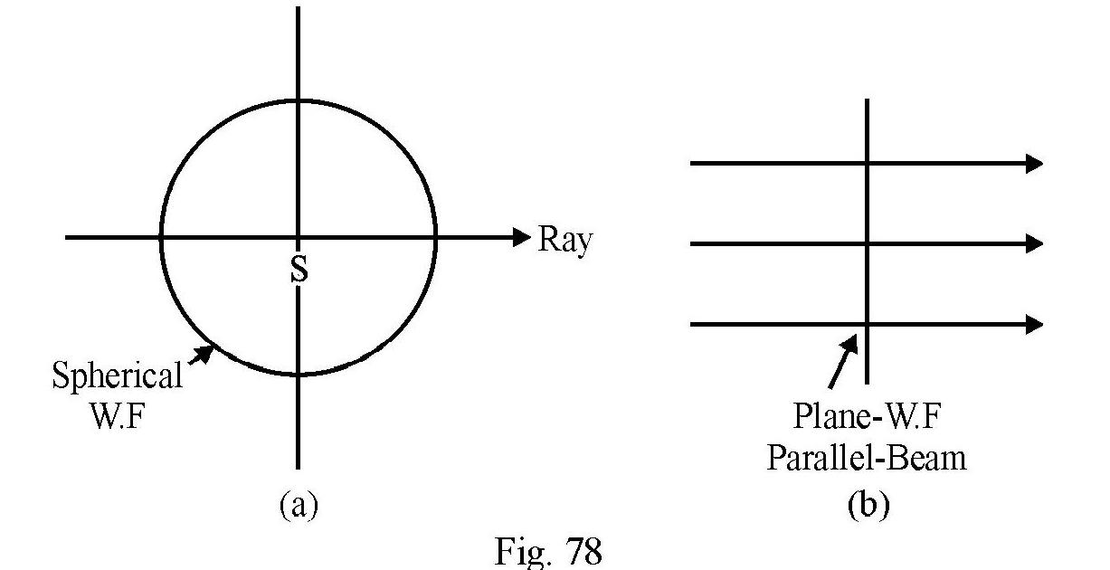
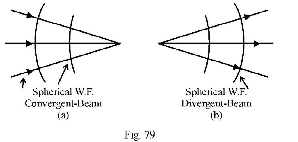
The concept of wave front is a ‘geometrical’ idea used to visulise propagation of waves. The wave-front, at any time , is the locus of all those points of medium that are in phase. For a point source ; the wave front is a sphere of radius with as center shown in Fig 78(a). V is speed of waves in medium. The direction of the ray at any point on wave front is in the direction of normal to wave front at the point considred. Figure- 78 (b) and Fig 79(a) and (b); show wave front of a (i) a parallel beam; (ii) convergent beam and (iii) divergent beam.
Huyghen’s Principal of Secondary Wave-Lets
Huyghen’s principal is a ‘geometrical way’ to describe propagation of waves via wave front in a medium. Given a wave front say at ; the position and shape of W.F at is obtained using Huyghen’s principle. According to this principle:
(1) Regard every point on given W.F as an imaginary point source. The disturbance in medium due to this imaginary point source is known as a secondary wavelet.
(2) The speed of secondary wavelets depend on the nature of medium in which the wavelets propagate.
(3) The amplitude of secondary wavelets in a direction making an angle with the forward direction of wave motion, is proportional to .
(4) The new W.F at ; is the tangential plane or envelope of all secondary wavelets.
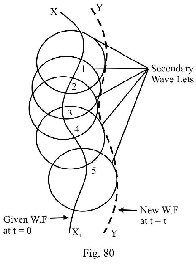
Figure- 80 shows a given wave front at . The new-wave front at is obtained using Huyghen’s principal. In a homogeneous, isotropic medium shape ofW.F remains same. When light undergoes reflection or refraction in general; the shape and orientation ofW.F changes.
INTERFERENCE OF WAVES
Consider two or more than two waves arriving at the same point of a medium simultaneously. The resultant disturbance at this point is the resultant of the disturbance due to each individual wave, in accordance with the principle of superposition of waves. This results in a modification (or redistribution) of energy (or intensity) in the medium. This is known as interference of waves. Interference is easily observed with (i) sound (ii) water waves etc.
Figure- 81 shows two identical source of waves and . The disturbance from the two arrives at a point on screen travelling path and respectively. The “path difference” between the two disturbances at . If the two disturbances arrive IN PHASE at ; they add up. The resultant disturbance is more. We say constructive interference has occured at . Expressed mathematically
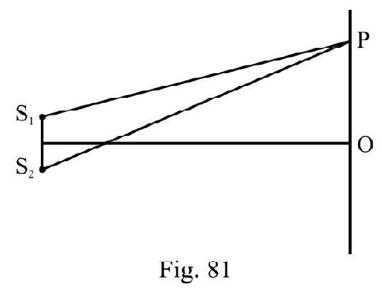
Figure- 81
If the two disturbances arrive OUT OF PHASE at they substract from one another. The resultant disturbance is less than due to each individual wave. We say destructive interference has occured. Condition for destructive interference is
In terms of phase difference, ; the conditions of constructive and destructive interference is
In writting aligned (1), (2) and (3) we have assumed there is no intial path or phase difference between and . In general if is the initial path difference (or is the initial phase difference) between and ; aligned (3) is rewritten as
Interference between Two Sources of Light - Coherent Sources
The interference effect at any point is to be observed by the eye. Due to persistence of vision eye cannot detect rapid changes in intensity. To observe interference, we want the effect at any point to remains same at all times. This will be so if does not depend on time. For a given set up; for a particular point is time independent; therefore will not depend on time if remains same at all times. Any two sources of light having same phase difference at all times are known as coherent sources. To observe
interference with light we must have coherent sources.
Independent; idential sources of light are not coherent sources. Their phase difference changes times in one second. With such sources the interference pattern changes times in one second. The eye cannot follow such rapids changes. The interference produced is, therefore, not observed. To observe interference with light we have to produce coherent sources from an incohorent source. This can be achieved by using
(i) reflection
(ii) refraction
(iii) multiple reflection and refraction of light
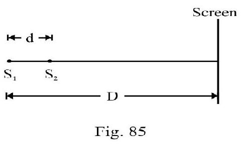
Young’s Double Slit Experiment
Figure- 82 shows standard Y.D.S experimental setup. and are two very fine slits distance apart in an opaque screen. is a monochromatic source emitting light of wave length . A screen is placed at a distance ) from and . is an incoherent source. Since ; the disturbance from reaches and simultaneously. Though phase of and changes with time; their phase difference is zero at all times. and behave as two coherent sources is any point on screen at a distance from centeral point . It can be shown that
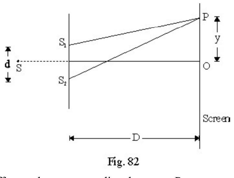
The path difference between two disturbances at
For constructive interference
or
aligned (2) gives location of points of constructive interference.
For destructive interference
aligned (3) gives location of points of distructive interference on screen.
The distance between any two consecutive bright or dark fringes is
is known as fringe width. is same for bright or dark fringes. We say fringes, in interference, are equispaced. The angular width, ; of a fringe is
Note that is directly proportional to ; however is independent of .
Let and be the intensity of interferring sources and . and is amplitude of oscillations due to and . Then
The resultant intensity; ; at point where the two disturbances arrive having a phase difference is
At points of constructive interference; or
At points ofdesturctive interference; or
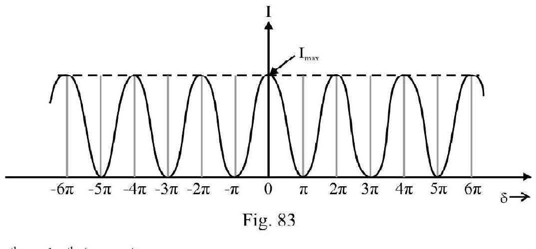
In standard Y.D.S, experiment; . aligned (6) is reduced to
where
There is no violation of law of conservation of energy in interference. There is only redistruction of energy. Average energy between one and
Figure- 83 shows I vs graph. Note all bright fringes are equibright.
Distance between and
(i) bright fringes , (ii) dark fringes
Distance between dark and bright fringe
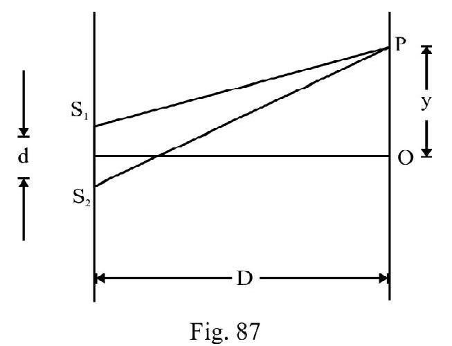
Modified Y.D.S Experiment
Figure- 84 shows a modified Y.D.S experimental set up. Here is not symmetrically placed with respect to and . Due to this there is an intial path difference between and .
We can also say there is an initial phase difference between and . Obviously . The total path
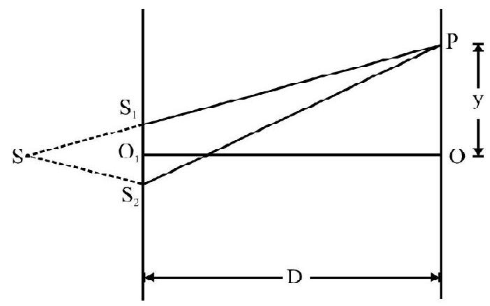
Figure- 84 difference at any point on screen is
The condition for constructive and distructive interference is Constructive interference
Destructive interference
The centeral maximum is not located at . Let be the position of central maximum. Putting ; From equation (1) we have
or
The negative sign shows that centeral fringe is below point . If in the modified set up the centeral fringe shifts above point . The fringe width , however remains same.
Let a thin film of thickness ; refractive index be introduced is the path of one of the two interferring beams; say ; in standard Young’s double slit experiment. The path difference, , between the two disturbances at point is
A thickness of film is equivalent to a path in air. Therefore,
This a change in the path difference. Due to this the fringe pattern shifts but remains same. For constructive interference
The centeral fringe shift from by a distance is obtained by putting in aligned (5). Therefore
Let be the fringe shift. Then
White Light Fringes
Replace monochromatic source by a white source of light in Y.D.S experiment. We observe
(1) Centeral fringe is white.
(2) Coloured fringes of each of the constituent wave lengths of white source are produced simultaneously on screen.
(3) is minimum for violet and maximum for red colour. Moving away from centeral fringe for a particular order of interferring (i.e. a particular value of ); the first coloured fringe is violet and the last is red.
(4) Due to superposition of different coloured fringe patterns; the number of fringes (coloured) observed clearly is small ( to 8 ) only.
Example-42:
Two coherent sources and seperated by a small distance are shown in Figure- 85. The fringes obtained on screen are:
(a) points
(b) straight lines
(c) semi-circle
(d) coincenteric circles
Show Answer
Solution:
is any point on screen. With as center draw a circle of radius meeting at .
The condition for say maximum is
For a particular value of fringe is locii of all point having same value of . The fringes therefore are circular with center .
Example-43:
Y.D.S experiment is carried out by using green; red and blue light; one colour at a time. The fringe widths recorded are and respectively. Then
(a)
(b)
(c)
(d)
Show Answer
Solution:
In Y.D.S experiment fringe width is directly proportional to . We know . Hence . The correct choice is (d).
Example-44:
In a Young’s double slit experiment 12 fringes are observed to be formed on a certain segment of the screen when light of is used. If the wave length of light is changed to , number offringes observed in the same segment of the screen is
(a) 12
(b) 18
(c) 24
(d) 30
Show Answer
Solution:
Let be the length of the segment of screen considered. Let and be the fringe width for and respectively. Let and be the number of fringes of and observed. Obviously
Correct choice is (b)
Example-45:
In Young’s double slit experiment . The distance of 10th dark fringe from centeral fringe is . What is of light used?
Show Answer
Solution:
The distance of dark fringe from the centeral fringe (zero order bright fringe)
where is fringe width of fringes observed.
or
Now and ; therefore
Example-46:
In a Y.D.S experiment . At a point on screen distant from the centeral point the intensity is of intensity of a bright fringe. What is wave length of light used?
Show Answer
Solution:
In Y.D.S experiment the intensity I at a point distant y from the central point is
Given ; therefore
or
or
Example-47:
White light is used to illuminate the two slits in Young’s double slit experiment. The separation between the two slits is and the screen is at a distance from the slits. At a point on screen directly opposite one of the slits certain waves lengths are missing. Some of the missing
wave lengths are:
(a)
(b)
(c)
(d)
Show Answer
Solution:
The wave lengths that are missing at the point , considered, are the ones undergoing destructive interference. The path difference, ; between the two interferring beams at is
For destructive interferrence
or
For different allowed values of is
The missing wave length is given by (a) and (c).
Example-48:
In Y.D.S experiment the two slits act as coherent sources of amplitude and wave length . In an another experiment with the same set up the two slit sources of equal amplitude and wave length , but are incoherent. What is the ratio of intensity of light at mid-point of screen in the first and the second case?
Show Answer
Solution:
In first case the interferring sources are coherent, constructive interference takes place at mid-point . The resultant intensity.
In second the sources are incoherent no interferring is observed at mid-point . The resultant intensity is
Example-49:
In a Y.D.S experiment the intensity of each interferring source is . The intensity of one of the two sources is reduced by . Express the change in the intensity of maximum and minimum now observed as a fraction of maximum intensity observed earlier.
Show Answer
Solution:
Let and be the intensity of maximum and minimum observed initially. Then
In second case. Now
Let be the intensity of maximum now observed.
Let be the intensity of the minimum observed now.
Example-50:
In Y.D.S experimental set up two wave length of and are used. What is the minimum distance from the centeral maximum where their maximas coincide? Take .
Show Answer
Solution:
In Figure- 87, is point where maximas of and coincide for first time after centeral maximum. Let and be fringe width for wave length and . Obviously . Let there be bright fringes of in distance . There will be bright fringes of . Obviously , .
or
or
This means bright fringe of . Coincides with bright fringes of . Therefore
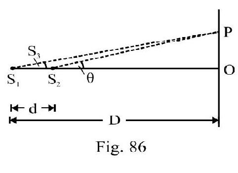
Example-51:
In Y.D.S experimental set up shown in Figure- 88; the distance between slits and is is wavelength of light. A parallel beam is incident making an angle with plane of and . For point on screen; the condition of (i) constructive (ii) destructive interference is
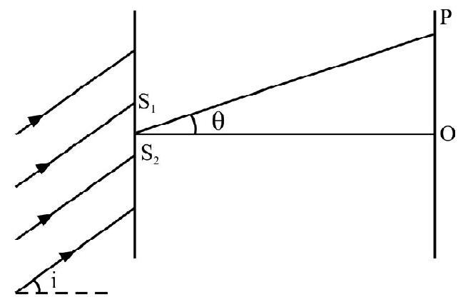
Figure- 88
(a) dsini .
(b) .
(c) .
(d) .
Show Answer
Solution:
There is on initial path difference between and . From right angled triangle shown in Fig 89.
or
At point on screen the two disturbances arrived having a path difference, . From right angled triangle
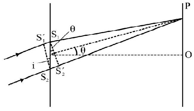
The total path difference between the two disturbance at is
Figure- 89
For constructive interference
and for distructive interference
The correct choice is (d)
Example-52:
A Young’s double slit experiment is performed using monochromatic light of wave length .
Express intensity on a point where two waves arrive having a path difference as a percentage of maximum intensity.
Show Answer
Solution:
In Y.D.S experiment the intensity I at any point on a screen where the two waves arrive having a phase difference is
Given ; therefore
Example-53:
A glass plate of refractive index 1.5 is coated with a layer of thickness and refractive index 1.8. Light of wave length travelling in air is incident normally on the layer. It is partly reflected at the upper and the lower surface of the layer and the two reflected rays interfere. Write the condition of constructive interferece. It ; obtain the least value at for which rays interfere constructively.
Show Answer
Solution:
In Figure- is film of thickness ; refractive index . DCEF is glass plate . PQ is a ray incident nearly normally on upper face . QR is reflected ray. TU is ray produced ray due to reflection at lower face of the film. Interference occurs between and TU. For nomal incidence path difference . The reflection at upper face is from boundary of a denser medium. There is an
additional path difference between the two interferring beams.
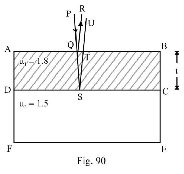
The total path differences
For constructive interference
or
For minimum value of . Therefore
DIFFRACTION
The bending of waves arround the edge of an obstacle in their path and their penetration into the region of ‘geometrical shadow’ is known as diffraction. All type of waves undergo diffraction. Diffraction is easily observed with
(1) sound waves
(2) waves on surface of water
However apparently light does not exhibet differaction. This is due to very small wave length of visible light. To observe diffraction size of obstacle must be comparable to wave length of waves used. For observing differaction of light the size of obstacle used must be very small (comparable to ). When this is done differaction of light is also easily observed.
Diffraction at a Single Slit
Figure- 91 shows the single slit experimental set up. (of the order of a fraction of a m.m) is a slit in an opaque screen illuminated with a monochromatic parallel beam. The incident W.F on slit is a plane wave front. The screen is placed at a distance from the slit. If light travels in straight line the part of screen should be uniformly bright. The screen above and below should be completely dark. This is not observed. The intensity on screen varies. The intensity variation is shown in Figure- 91.
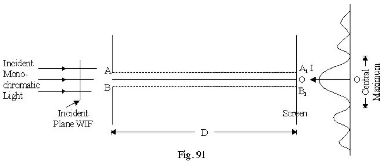
The central point is maximum bright. It is sourrounded by alternate maximas and minimas. The intensity of subsidary maximas observed decreases as shown in Figure- 91 . The observed intensity pattern is known as
diffraction pattern due to a single slit. The intensity pattern is observed due to bending of light around the edges of the slit i.e. due to diffraction of light.
The observed diffraction pattern is due to interference between secondary wavelets originating from plane of slit. We can say diffraction is interference between different parts of the same wave front. It can be shown that for secondary wavelets in a direction with the direction of incident light; if
is condition of minimum; and
is the condition of subsidary maxima. gives the principle maximum.
Let be the radius of the principle maximum observed i.e. the centeral maximum. It can be shown that
The half-angular width of principal maximum is; nearly
Diffraction of Light and Rectilinear Propagation of Light
We know light does not travel in straight line but bends around on appropriate obstacle in its path i.e. undergoes diffraction. Does this mean that “ray-otpics” is wrong! Strickly speaking ray optics is an approximation. However it is a very-very good approximation. When size of obstacle is large (of the order of a few cm or more) the diffraction effects are negligible.
Resolving Power
Two nearby objects or spectral lines are resolved if they appear as two images or two spectral lines. Normal human eye can see two objects seprate if they subtend a minimum angle of 1 " of arc on eye.
The sepration of close objects is termed as resolution and the ability of an optical instrument to produce seperate image of two such objects is known as resolving power of the instrument. Two neighbouring point objects are resolved by the lens system such as telescope or microscope is known as Geometrical resolution. When two close spectral lines (i.e. wave lengths) are resolved with the help of a prism; grating etc. we have spectral resolution.
Rayleigh’s Criterion
When two nearby objects are viewed by any optical instrument; due to wave nature of light (i.e. diffraction) we obtain two nearby diffraction patterns keeping one object fixed the other is moved nearer to the first the two diffraction patterns come nearer and start overlapping.
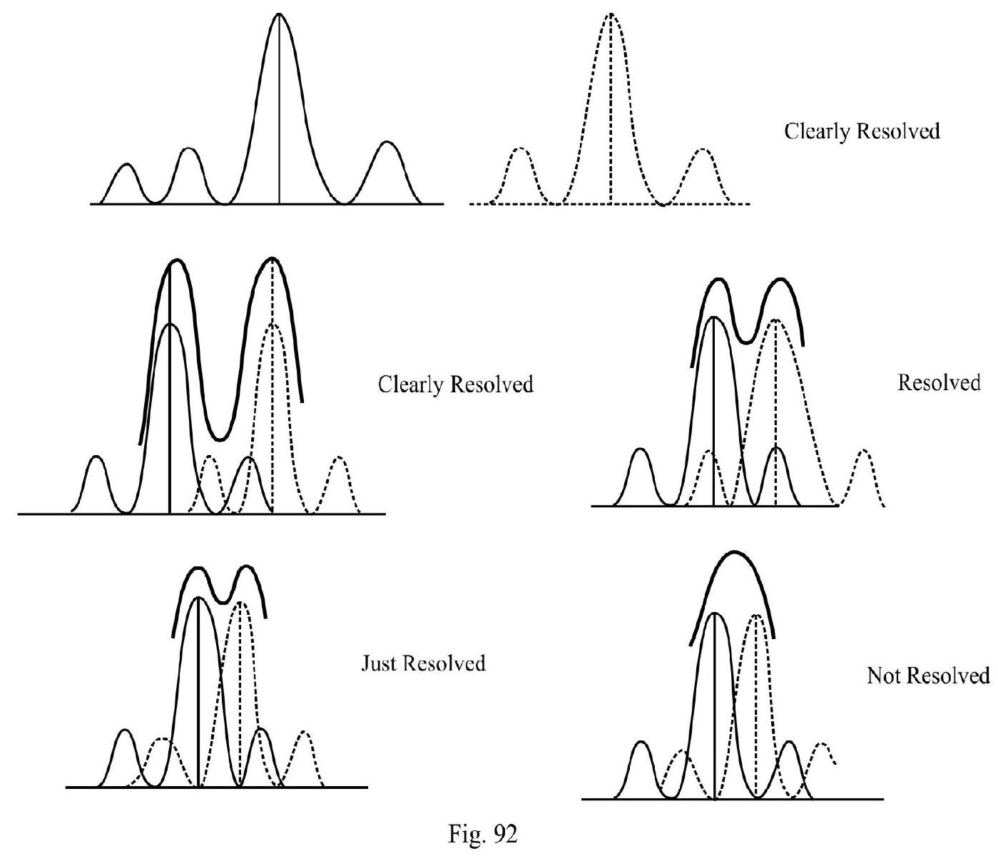
According to Lord Rayleight two objects or spectral lines are just resolved if the angular sepraction between the principle maxima in the diffraction pattern due to the two equals half the angular width of the principal maximum of the either of the two. Let be this minimum distance between the two point objects; the geometrical R.P . Let and be two spectral lines just resolved, the spectral resolving power .
Resolving Power of a Telescope
Let be the angular sepration between two objects just resolved according to Rayleigh’s criterion; the
R.P. of telescope
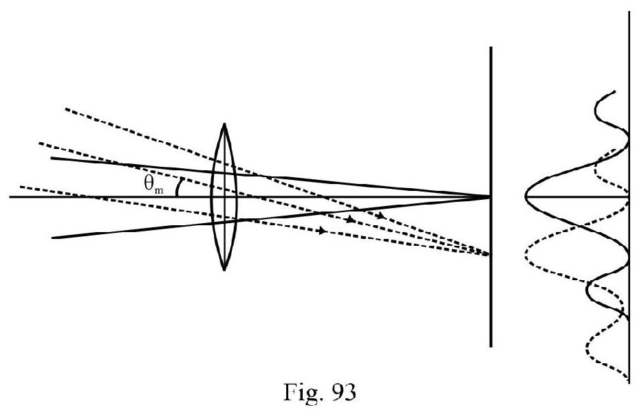
Let be the diameter of lens of telescope (i.e. aperture of telescope) and the wave length of light. Half angular width of principal maximum of diffraction pattern due to any one star (say the object being viewed)
R.P
More precise calculation show that
The magnifying power of a telescope; the resolving power are related to one another by the relation;
M.P of telescope R.P of telescope R.P of the eye.
Resolving Power of a Microscope
In Figure- is minimum distance between the two nearby objects forming diffraction pattern shown. The objects are just resolved. It can be shown that
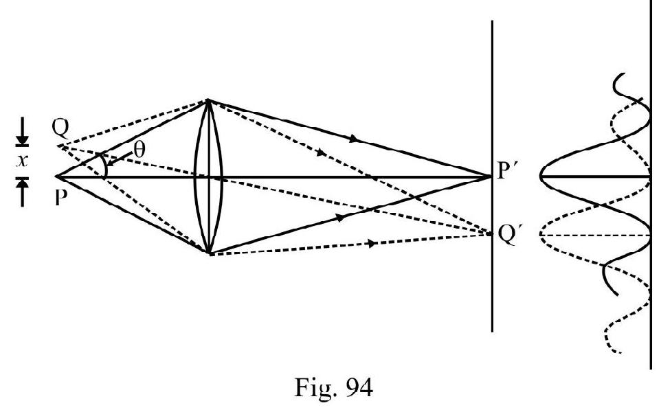
R.P . Lesser is value of more is resolving power. If the object and objective lens both are immersed in a liquid of refractive index ; the minimum values of for resolution works out to be known as the numerical aperature. Obviously is less if is more. This is the reason an oil immersion microscope has a higher R.P. Also if is less R.P is more. Therefore an ultra-microscope has a higher R.P. It can be shown that
Minimum M.P of microscope
Example-54
A single slit of width ’ ’ is illuminated with light of . The diffraction pattern is observed on a screen at a distance of from the slit. The diameter of principal maximum observed is . What is
(a) (i) d (ii) angular width of principal maximum.
(b) The wave length of light is increased by and is reduced by , what is percentage change in angular width of principal maximum.
(c) What is percentage change in distance of screen if angular width is to be restored to its earlier value. What is change in diameter of principal maximum observed now?
Show Answer
Solution:
(a) Given
radius of principal maximum
The distance of screen from slit
We know ; therefore
(b) Given
The angular width of principal maximum
where The angular width of principal maximum earlier.
Percentage change in angular width
(c) To get same angular width can change by any amount. The angular width does not depend on . However diameter of principal is directly proportional to ; therefore
Example-(55)
A single slit diffraction pattern is observed. What is the ratio of the intensity of different maxima’s observed? What is ratio of radii of different subsidary maxima’s observed.
Show Answer
Solution:
Let . be the intensity of centeral maximum, first, second,……. subsidary maxima’s observed. Very approximately
This because at centeral maximum all secondary wavelets from plane of slit undergo constructive interference. At first subsidary maximum nearly of secondary wavelets donot undergo distructive interference. At second maximum nearly of secondary wavelets from plane of slit donot undergo destructive interference with one another and so on.
The radii of subsidary maxima’s are given by
Example-(56)
Angular width of centeral maximum in a Fraunhoffer diffraction pattern of a slit is measured. The slit is illuminated with light of . When the slit is illuminated with another wave length the angular width decreases by . Calculate of light used. The same decrease in angular width of centeral maximum is obtained when the original apparats is immersed in a liquid. Find the refractive index of the liquid.
Show Answer
Solution:
Let be the angular width of centeral maximum when light of wave length is used. Then
width of the slit. Let be the angular width when light of is used. Then
Given
or
or
Let be refractive index of liquid in which original setup is immersed. The wave length of light inside liquid
is . Since change in angular width is same;
or
Example-(57)
A slit of width is placed in front of a lens of focal length and is illuminated normally with light of . The diameter of centeral maximum observed is . What is ?
Show Answer
Solution:
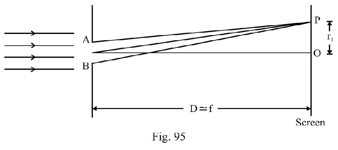
Figure- 95 shows slit ; illuminated with parallel beam of . The convex lens focus diffracted beam on screen. Therefore
distance between slit and screen
Let be radius of centeral maximum. We know . Given
Example-(58)
In Y.D.S experimental set up one of the slits is covered with an opaque paper. What change; if any, is observed in the pattern obtained on screen?
Show Answer
Solution:
In Y.D.S experiment interference pattern is observed. When one slit is blocked we obtain diffraction pattern on screen. The difference between the two are:
(1) Earlier fringes observed are equibright and equispaced. Now centeral maximum is most intense. The intensity of other maxima’s observed decreases. The fringes observed are not equispaced.
(2) The number of fringes observed in Y.S. D is quite large ( 20-30). The number of fringes observed clearly in diffraction is small .
Example-(59)
A telescope has an objective lens of aperture focal length . What is resolving power of telescope?
Show Answer
Solution:
The aparture of lens of telescope is the size of opening, i.e. . Let be the minimum angular separation between two stars that are just resolved. According to Rayleigh’s Criterion; equals half angular width of centeral maximum due to diffraction at lens; i.e.
R.P of telescope
POLARISATION
The phenomenon of polarisation is the preferrential selection of a particular direction of vibration from the various possible directions of vibrations.
In longitudinal waves there is only one direction of vibration, which is the direction of wave propagation, there is no possibility of any perferrential selection of direction of vibration. Therefore longitudinal waves cannot be polarised.
However in transverse waves vibrations can take place in any direction in a plane perpendicular to direction of wave motion. When there is no selection of a preferred direction of vibration i.e. no selection of preferred direction of vibration we say waves are unpolarised. However, if somehow, a particular direction of vibrations is selected and all other direction of vibrations are blocked we have plane polarised waves. The device used for this selection is known as a polariser. It is only transverse waves that can be polarised.
In case of light; in accordance with the E.M. theory we discuss about the vibration of electric field. Ordinary light is unpolarised, i.e. the oscillations of take place in all directions perpendicular to direction of wave propagation. A calcite or a tourmaline crystal, has the property of allowing oscillations of parallel to its axis to pass through and blocking all other direction of oscillations. It is used to convert ordinary (unpolarised) light from any source to plane polarised light. This crystal acts as a polariser.
In unpolarised light vibrations occur is all allowed directions of vibration. This is equivalent to two equal mutually perpendicular oscillations. A polariser allows all vibrations parallel to its axis to pass through and blocks the perpendicular component. If is intensity of unpolarised light incident on a polariser, the intensity
of plane polarised light emerging out of polarised is . It remains same irrespective of orientation of polariser. In other words when a polariser is rotated through are full circle about direction of propagation as axis; there is no change in intensity of light transmitted by the polariser. Figure- 96 shows symbolic representation of unpolarised and plane polarised light.
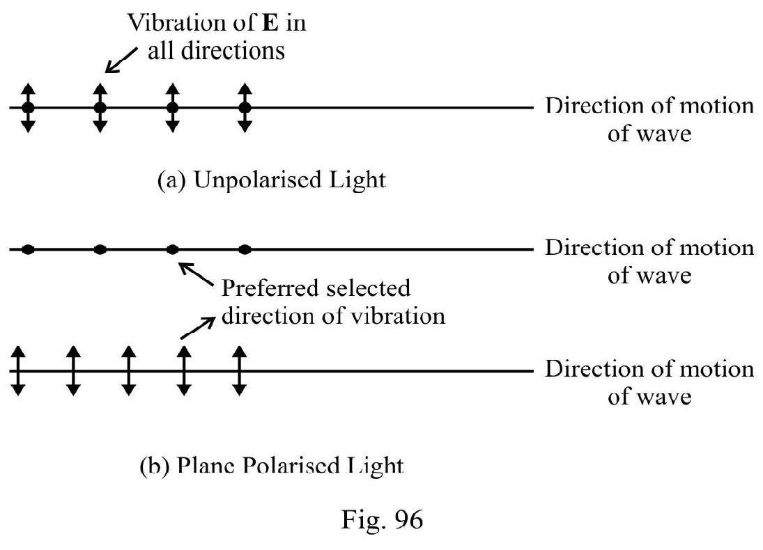
The plane in which vibration of are confined is known as plane of vibration. A plane perpendicular to plane of vibration is known as plane of polarisation.
Detection of Plane Polarised Light the Analyser
Our eye cannot detect whether light used is unpolarised or plane polarised. To do this we use another tourmaline or calcite crystal. This is known as analyser.
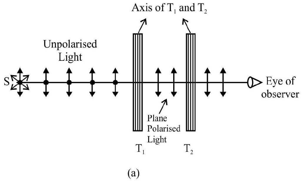
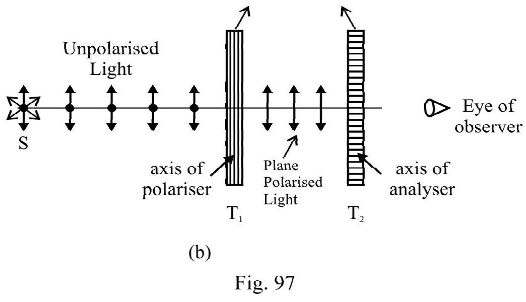
In Figure- 97 (a) and (b) is ordinary source of light emitting unpolarised light. is polariser and is analyser. In Figure- 97 (a) axis of polariser and analyer are parallel; the vibrations passing through also pass through . The eye observes light passing through . Keeping fixed is rotated about direction of propagation of light as axis. The intensity of light passing through starts decreasing. In Figure- 97 (b); has accquired an orientation when its axis has rotated by . The vibrations incident on are blocked. The intensity of light transmitted is zero. In one full rotation of ; there are
(1) two positions when intensity of light transmitted is maximum (i.e. axis of and are parallel or antiparallel).
(2) two positions when intensity of light transmitted by is zero. This is when axis of make on angle of or with axis of .
We summarise by concluding:
(1) When unpolarised light passes through an analyser; intensity of transmitted light is of incident intensity. However on rotating analyser about direction of propagation as axis there is no variation in intensity oflight passing through.
(2) When plane polarised light passes through analyser and analyswer is rotated through one full circle; there is a variation in intensity of light passing through and intensity is zero twice in one full rotation.
Brewster’s Law
When unpolarised incident light undergoes reflection from a medium of refractive index ; there is one angle of incidence such that the reflected light is plane polarised. is known as the polarising angle of incidence. According to Brewster’s law.
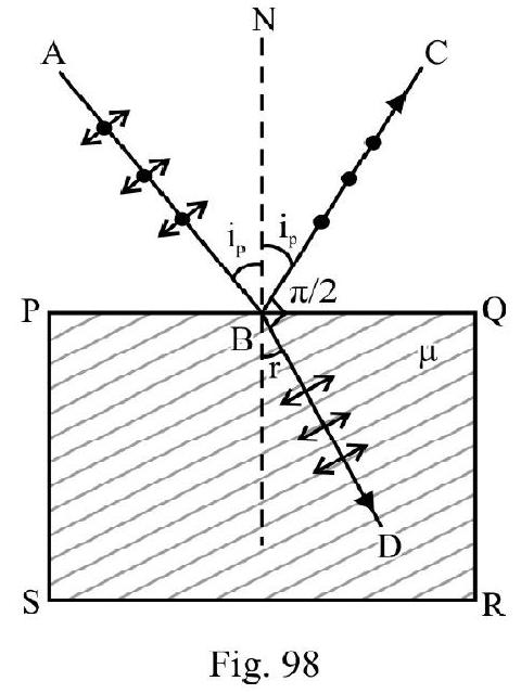
Figure- 98 shows a block PQRS of a medium of refractive index . AB is an incident unpolarised ray; incident at polarising angle of incidence and are reflected in mutually perpendicular planes. The reflected are refracted ray make an angle of with one another; i.e.
.
The Malus Law
A plane polarised beam of intensity is incident on an analyser. is angle between axis of anglyser and polariser. I is intensity of light transmitted by analyser. According to Malus law
Uses of Polaroids
(1) Sun glasses fitted with polaroid sheets reduce glare of sun.
(2) The glare of head lights of a car; during night driving; is reduced using wind shields made of polariod sheets.
(3) Polariods used in projection and viewing of three dimensional motion pictures.
(4) Polaroids are used to improve colour contrast in old paintings.
(5) Optical stress analyser makes use of polaroids.
Example-60:
Light is reflected from a material in which speed of light is . What is polarising angle of incidence? Does this angle depend on wave length of light used?
Show Answer
Solution:
The refractive index of reflector
Let be the polarising angle of incidence. From Brewster’s law
or
The value of depends on wave length of incident light; therefore also depends on . For visible light is maximum for violet and minimum for red colour. Therefore is also maximum for violet and minimum for red colour.
Example-61:
(a) Figure- 99 shows a source and are two polaroids. is intensity of light incident on . Axis of and are inclined to one another at . What is ratio of intensity of light observed by and .
(b) Keeping fixed is rotated through one full circle about incident ray as axis. Draw a graph figure- 99 showing variation of intensity observed by and .
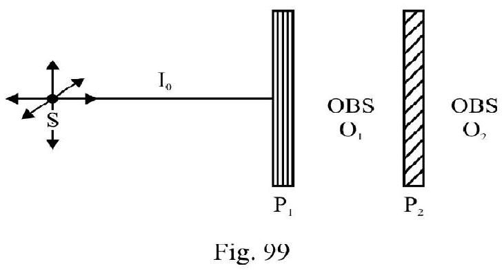
Show Answer
Solution:
(a) The incident light from is unpolarised. acts as a polariser.
Intensity of light observed by
has plane polarised light incident on it. Initially;
Angle between axis of analyser and polariser (Given)
Let be intensity of light observed by . From Malus law
(b) On rotating ; there is no change in intensity of light observed by . It remains same, having intensity as shown in Fig 100.
Let be the angle through which axis of has been rotated. The instantaneous angle between axis of and is
Therefore ; instantaneous intensity of light, observed by is
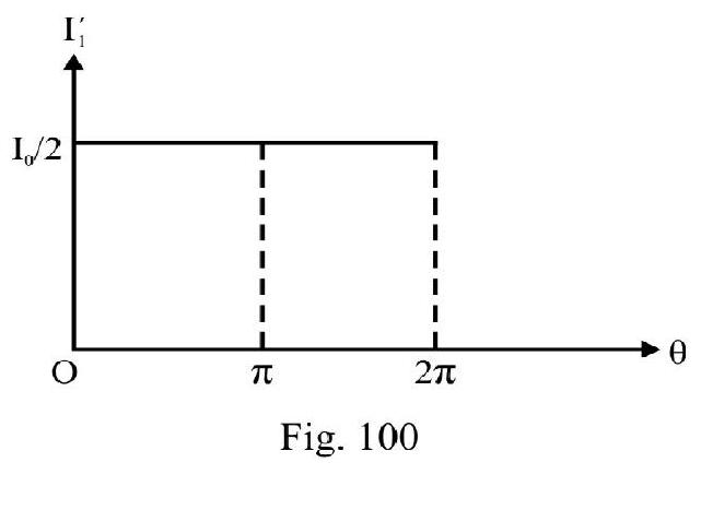
is zero if or
or
is maximum if . Therefore
or or
The variation of with is shown in Figure- 101.
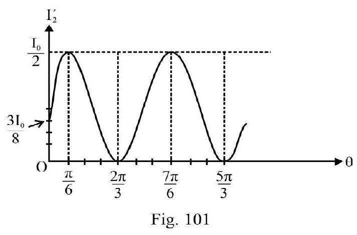
PROBLEMS FOR PRACTICE
1. An object high is placed at a distance of from a (i) concave mirror (ii) convex mirror of focal lenth . In each case what is position, nature and length of image formed?
Show Answer
[Answer: (i) Real; inverted; (ii) Virtual erect; ]
2. A concave mirror forms an image of length of an object of length at a distance of from the mirror. What is radius of curvature and power of mirror?
Show Answer
[Answer: ]
3. What is distance of an object from a concave mirror of power so as to obtain an image twice the length of the object?
Show Answer
[Answer: or ]
4. A concave mirror produces an image on a screen of an object at a distance of . The image is twice the length of object. What is change in position of object so that image formed is three times the length of the object?
Show Answer
[Answer: to towards mirror]
5. An object is placed in front of a convex mirror. A plane mirror is placed in between convex mirror and object at a distance of from the convex mirror. There is no parallex between the image formed by the two mirrors. What is focal length of convex mirror?
Show Answer
[Answer: ]
6. A plane mirror is placed in front of a concave mirror of radius of curvature . An object is placed in between the two mirros so that the first image formed by both mirror coincide. What is distance of object from plane mirror?
Show Answer
[Answer: ]
7. Two objects and placed one by one in front of a concave mirror of power form image of same size. Length of is three times that of M. Distance of from the mirror is . What is position of M?
Show Answer
[Answer: ]
8. Sun subtends an angle of of arc on earth. A concave mirror forms an image of Sun of diameter on a screen. What is focal length and power of the mirror?
Show Answer
[Answer: ]
9. A concave mirror of radius of curvature and convex mirror of power are placed coaxially facing one another apart. A point object is placed on the common axis at a distance of from the convex mirror. What is position, nature of the image formed by the system; due to successive reflections first at concave and then convex mirror?
Show Answer
[Answer: Virtual; behind the convex mirror]
10. An object is moved towards a concave mirror; the real image formed moves from to . What is focal length of mirror?
Show Answer
[Answer: ]
11. Speed of light in glass is . What is absolute refractive index of glass? Is refractive index of glass same for violet and yellow colour?
Show Answer
[Answer: No. is more for violet than yellow colour]
12. A ray of light is incident on a plane boundary from a medium of refractive index . The refractive index of second medium is . The ray is partially reflected and partially refracted. The reflected and the refracted rays are mutually perpendicular. What is angle of incidence?
Show Answer
13. A glass slab of thickness contains same number of waves as are there in of water for monochromatic light of same . What is ?
Show Answer
[Answer: 1.67]
14. A ray of light is incident at angle with a rectangular plate of thickness and refractive index . What is net deviation and lateral displacement as the ray emerges out of slab?
Show Answer
15. Abeaker is filled with water of refractive index 1.33 up to . Alayer thick of an immisible oil of refractive index 1.4 is formed above water. When viewed from above what is
(i) apparent depth of a point on the inner bottom of beaker.
(ii) equivalent refractive index of the arrangment?
Show Answer
[Answer: (i) (ii) 1.37 ]
16. A glass beaker has a base thick . The beaker has two immisible liquids I and II poured into it upto to a total height of . The depth of liquid is and its refractive index is 1.40 . A point on the outer bottom of beaker appears raised by when viewed directly from above. What is refractive index of liquid II?
Show Answer
[Answer: 1.30]
17. A point object is placed in front of a plane mirror. A glass slab ( ) of thickness is placed in between plane mirror and point object. What is distance between the object and its image formed by the plane mirror?
Show Answer
[Answer: ]
18. A point object is placed in front of concave mirror of power . A glass slab of thickness is placed with its nearer edge at a distance of from concave mirror; in betwwen the mirror and object. What is position of image formed?
Show Answer
[Answer: ]
19. A rectangular glass slab is placed on a horizontal printed page. What is minimum value of of glass so that the letters on the page are not visible from any of the vertical face of slab?
Show Answer
[Answer:
20. A point source is placed at the bottom of a vessel containing a liquid of refractive index .A person is viewing the source from above the surface. There is an opaque disc of radius floating on the surface. The center of disc is vertically above . The liquid in vassel is gradually drained out through a tap. What is maximum height of the liquid for which the source cannot be seen at all from above?
Show Answer
[Answer: ]
21. A prism of a material of has a refracting angle A. A ray of light incident on one face emerges out from the other face. What is maximum possible value of A?
Show Answer
[Answer: ]
22. A prism produces a minimum deviation of . The prism produces same deviation of for angle of incidence of either or . What is
(i) refracting angle
(ii) refractive index of prism
Show Answer
[Answer: (i) (ii) 1.648 ]
23. An equilateral glass prism has a monchromatic ray incident at an angle of . What is the angle of
(i) emergence
(ii) deviation?
(iii) Is the incident ray undergoing minimum deviation?
Show Answer
[Answer: (i) (ii) (iii) yes]
24. The refractive index of the material of prism of refracting angle is 1.6 for some monochromatic ray. What would be the minimum angle of incidence of this ray on the prism so that no total internal reflection takes place as rays emerge out of the prism?
Show Answer
[Answer:
25. Figure- 102 shows an equilateral prism LMN. The path of an incident ray is as shown in Figure- 102. Angle . What is of the material of prism?
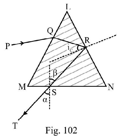
Show Answer
[Answer: 1.66
Figure- 102
26. For “crown glass” . For quartz glass. .
A quartz prism of angle is in contact with a crown glass prism of angle ; such that there is no net deviation. What is ? What is angular dispersion due to the arrangment?
Show Answer
[Answer: ]
27. A very thin glass hollow sphere of radius is filled with water . A mark on surface is viewed from the diamaterically opposite end. What is the position and nature of image viewed?
Show Answer
[Answer: away from the end of sphere from the side of new; virtual]
28. Two concave glass refracting surfaces each of radius ; refractive index are facing one another a distance 2 apart. A point Object is placed on the common axis at a distance of from on surface. What is distance between the images of formed by each refracting surface?
Show Answer
[Answer: ]
29. A concave lens made of glass ( has a power of . The lens is immersed completely in (i) Water ( ) (ii) carbon-bisuphide . In each case what is focal length and nature of lens?
Show Answer
[Answer: (i) concave; , (ii) convex; ]
30. A convex lens of glass has a focal length of . The lens is immersed completely in a liquid. The change in power of lens is . What is refractive index of liquid?
Show Answer
[Answer: 1.33]
31. A lens forms an image of a square of side placed at a distance of on a screen. The area enclosed by the image formed is .
(i) What is distance between object and screen?
(ii) What is focal length of lens?
Show Answer
[Answer: (i) (ii) ]
32. An object and its real image are at a distance of and respectively from the two focii of lens. What is
(i) focal length of lens
(ii) magnification?
Show Answer
[Answer: (i) (ii) -1.27 ]
33. A lamp and screen are apart. A convex lens placed in between projects the image of lamp on screen in two positions apart.
(i) What is focal length of lens.
(ii) What is magnification in each position of lens?
Show Answer
34. An equi-convex lens has a power of . The lens is placed with its lower surface in contact with water . A parallel of beam light parallel to principle axis of lens is incident in air. What is the distance of image formed in water from the lens? What is change in position of image if the entire system is immersed completely in water?
Show Answer
[Answer: , increases by ]
35. Two thin co-axial lenses and are in contact. An object is placed at a distance of from the combination. The image formed on a screen has a size three times that of object. B is concave lens of power ; what is focal length and power of A?
Show Answer
[Answer: ]
36. A plano-convex lens of focal length is fixed on one face of a hollow box with convex surface facing the object. An object high is placed in front oflens. What is size of image formed when box is (a) empty (b) filled with a liquid of refractive index 1.33? Refractive index of material of lens .
Show Answer
[Answer: (a) (b) ]
37. A plano-convex lens of radius of curvature acts like a concave mirror of radius of curvature when its plane surface is silvered. What is of the material of lens?
Show Answer
[Answer: 1.5 ]
38. A convex lens placed in between an object and screen projects image having a size twice that of the object. On moving the lens by away again a sharp image is projected on screen. What is focal leng length of lens?
Show Answer
[Answer: ]
39. A convex lens of power has an object placed in front. The lens projects image on a screen. A concave lens is placed in between convex lens and screen at a distance of from convex lens. The screen has to be moved away by so that again a sharp image is projected on it. What is focal length of concave lens?
Show Answer
[Answer: ]
40. A convex lens of focal length is placed in front of a convex mirror, co-axially at a distance of . An object at a distance of fron the lens, has no parallex with its image formed by the system. What is radius of curvature of convex mirror?
Show Answer
[Answer: ]
41. In Y.D.S experiment the two slits are a distance apart. Interference fringes are observed on a screen away from interferring sources. 20 fringes are observed in a distance of from centeral fringe. What is ? What is percentage change in fringe width if distance of the screen is doubled and seperation between slits is halved?
Show Answer
[Answer: (increases)]
42. Monochromatic light of wave length is used in Y.D.S experiment. .
(a) Distance between 8 th bright fringe and centeral fringe is .
(b) Distance of dark fringe from centeral fringe is .
In each case what is ?
Show Answer
43. A beam of light has two wave lengths and is used to observe interference inYoung’s double slit experiment and . What is minimum distance on screen from centeral fringe where bright fringes of the two wave lengths coincide?
Show Answer
[Answer: ]
44. In an interference experiment the two interferring sources have intensities respectively. At a point the two disturbances arrive having a path difference of ; whereas at point , the path
difference is . What is ratio of resultant intensity at and ?
Show Answer
[Answer: 1.527
45. In a Y.D.S. experiment interference is observed using monochromatic light of . . Express intensity at a point distance from centeral point as a percentage of intensity of centeral fringe.
Show Answer
[Answer: ]
46. In an interference experiment a sheet of thickness of a material in which speed of light is ; is introduced in the path of one of the two inteferring sources. The centeral fringe shifts to a point where originally bright fringe was located. . What is ?
Show Answer
[Answer: ]
47. In a Y.D.S experiment using monochromatic light, the fringe pattern shifts by a certain distance when a mica sheet of thickness 1.964 microns; is placed in the path of one of the two waves. The mica sheet is removed and the distance between the slits and screen is doubled. It is observed that the distance between successive maxima and minima now observed is same as the fringe shift observed upon introduction of mica sheet. Calculate of light used.
Show Answer
[Answer: ]
48. Two coherent sources of intensity ratio are used in an interference experiment. What is in the interference pattern observed?
Show Answer
[Answer: 49:9]
49. Two glass plates A and B are kept near one another as shown in Figure- 103. A monochromatic beam of intensity I is incident on as shown. Each plate reflects of light incident on it. What is due to interference between incident light reflected by A and B?
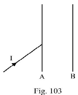
Show Answer
[Answer: 49.1]
50. Light of is incident normally on a single slit. The distance between the first minimum on either side of centeral maximum is . The screen is at a distance of from slit.
(i) What is width of slit?
(ii) What is half-angular width of centeral maximum?
(iii) What is ratio of radii of centeral maximum and second subsidary maximum?
Show Answer
[Answer: (i) (ii) 2.27×10⁻⁴ radian (iii) 5:1]
51. A plane wave-front falls on a slit wide. A convex lens of focal length placed behind the slit focuses diffracted beam on a screen. What is linear distance of
(i) first minima
(ii) second maxima from the centeral maxima?
Show Answer
[Answer: (i) (ii) ]
52. A telescope has an aperture of and focal length of O-lens is . Light of from two distant stars enters the telescope. What is seperation (angular) between the two stars if they just appear resolved?
Show Answer
[Answer: radian]
53. Two polarising sheets are placed with their axis parallel. The intensity of transmitted light is I. Through what angle one of the two sheets be rotatted so that intensity of light transmitted is of I?
Show Answer
[Answer: or ]
54. An unpolarised beam of intensity is incident on a polariser. The axis of analyser is at an angle of with axis of polariser. What is intensity of light transmitted by the analyser?
Show Answer
[Answer: ]
55. Unpolarised beam of light is incident on a reflector such that the reflected beam is plane polarised. The speed of light in reflected is . What is angle of incidence?
Show Answer
[Answer:
Question Bank
Key Learning Points
1. Ray optics is study of light using rectilinear propagation of light in an isotropic homogeneous medium.
2. A smooth surface throws back, in same medium light incident on it. This is reflection of light. The law of reflection states:
Angle of incidence angle of reflection
3. A spherical mirror is a part of a hollow sphere. The mirror is convex or concave denpending on the polished side of mirror. The principal axis of mirror is a line joining the pole and the center of curvature.
4. For simplicity of analysis we consider paraxial incident rays. These are rays making small angle with principal axis, such that .
5. The distance of an object; image center of curvature etc. is a pure number. However position of object; image; center of curvature etc. is an appropriate distance with a + or - sign prefixed according to co-ordinate convention of signs.
6. In co-ordinate convention, (i) the pole of reflecting surface or optical center of refracting surface is origin of co-ordinates (ii) incident rays proceed from left to right (iii) principal axis, in direction of incident ray is direction of positive -axis. (iv) y axis above principal axis is the positive direction (v) clockwise angles are positive.
etc. are co-ordinates of object, image, center of curvature etc.
7. The reflection formula for a spherical mirror is
object position, image position; position of center of curvature etc. When using reflection formula proper sign of known parameters must be prefixed before the appropriate distance.
8. Incident parallel beam, parallel to principle.axis after reflection meets or appears to meet principle. axis at a point F. F is the focus of spherical mirror. Position of gives focal length ( ). Also .
9. The transverse magnification
10. A concave mirror is a converging mirror and convex mirror is a diverging mirror. The power of the mirror is
11. The signs and their interpretation of u, v, R, fetc. are summarised below.
|
|
|
|
| 1. |
Mirror |
1) Concave
2) Convex |
and are negative
and are positive |
| 2. |
Object |
1) Real
2) Virtual |
is negative
is positive |
| 3. |
Image |
1) Real
2) Virtual |
is negative
is positive |
| 4. |
Magnification |
1) Positive
2) Negative
3)
4) |
Image is erect
Image is inverted
Image is enlarged
Image is diminished |
12. For a real object a concave mirror;
(i) can form virtual or real image depending on position of object.
(ii) real image formed is always inverted.
(iii) real image formed can be diminished or enlarged depending on position of object.
(iv) virtual image formed is erect and enlarged.
(v) when object moves towards mirror the image moves away from the mirror.
13. For a convex mirror, the image of a real object is always virtual, erect and diminished irrespective of position of object.
14. Whenever light goes from one medium to another; in general, it either bends towards or away from normal at point of incidence. This is refraction of light.
15. The absolute refractive index n of a medium is
and denote relative permittivity and relative permeability of medium. can never be less than one.
16. The relative refractive index of medium 1 with respect to medium 2 is
The relative refractive index may be greater or less than one. Also
17. Snell’s law is the law of refraction of light. Let ibe angle of incidence of light in a medium of refractive index . Let be angle of refraction in second medium of refractive index . According to Snell’s law
18. When a monochromatic incident ray undergoes refraction through a parallel slab of thickness, ; refractive index n;
(i) The emergent ray is parallel to incident ray i.e. net deviation is zero.
(ii) The lateral displacement, ; depends on (1) angle of incidence (i), (2) thickness (t) and (3) refractive index (n) of the slab.
19. An object in a medium of refractive index is viewed, nearly normally, from above, say in air; the apparent depth is less than real depth . Also
The apparent shift
20. For a number of media of different thickness and refractive index
is real thickness and refractive index of slab.
21. Whenever light goes from a denser to a rarer medium; it bends away from normal i.e. . There is particular angle of incidence for which angle of refraction is . For there is no refracted ray in second medium. The entire incident energy is reflected back obeying law of reflection. This is known as total internal reflection. is known as critical angle of incidence. For light going from a medium of refractive index to a medium of refractive index ; the critical angle of
incidence, , is
22. A ray of light incident in water at air-water interface undergoes T.I.R if angle of incidence is more than .
23. For an incident ray going from glass to air, the critical angle of incidence is . A right angled issoceless prism of is known as totally reflecting prism.
24. The phenomenon of mirage is due to T.I.R. Diamonds shine because a ray inside diamond undergoes repeated T.I.R before at can emerge out.
25. A monochromatic incident ray in passing through a prism; undergoes a net deviation . The angle of deviation, ; where and denote the angle of incidence and angle of emergence. is refracting angle of prism.
26. For a given prism, (i.e. and A are constant) the angle of deviation ( ) varies with angle of incidence (i). For a particular angle of incidence the deviation is minimum. For minimum deviated ray; its path inside prism is parallel to the base of prism. Also
Therefore, refractive index of prism is
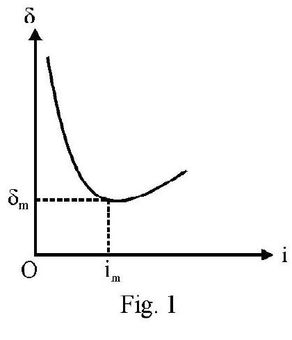
27. A white incident ray in passing through a prism breaks up into its consituent colours. This is known as despersion of light.
28. Dispersion takes place in a prism due to the variation of refractive index of the prism with wave length of incident light. According to Cauchy
and are constants, known as Cauchy’s constants.
29. When white light passes through a prism in undergoes:
(i) mean deviation
(ii) angular dispersion
and is deviation of violet and red colours respectively.
30. For a small angled prism of angle ; let and be refractive index for violet, mean (yellow) and red colour respectively. Then
31. For a prism, angular dispersion per unit mean deviation is known as dispersive power ( ) of material of prism. For small angled prisms is a constant for a particular material.
32. Consider a spherical surface seperating two media of refractive index and . For incident rays in medium , the relation between the object position (in medium ), the image position (in medium ) and radius of curvature ( ) of spherical surface is
This is known as refraction formula for a spherical surface.
33. Incident parallel beam, parallel to principal axis in medium ; after refraction meets or appears to meet principal axis at a point is the second principle focus. Position of gives second principal focal length . Also the focal length of spherical surface.
34. A point on principal axis where an object is placed or appears to be placed so that the refracted rays are parallel to principal axis. is known as a first principal focus. Position of gives the first principal focal length of spherical surface. Also
35. In terms of focal length, ; the refraction formula, at a spherical surface is
The magnification, ; is
36. A thin lens is a refracting medium, in general, bound by two spherical surfaces. The lens is either concave or convex. Each type has three varities.
37. Let a thin lens have refractive index and surfaces of radii of curvature and is refractive index of medium having object placed in it (i.e. incident rays are in medium 1). is the refractive index of the medium on the other side of lens. is the medium having refracted rays. For a thin lens;
and denote the object position and the image position respectively. This is refraction formula for a thin lens. Commonly . The above aligned reduces to
38. For a lens; the second principal focus is a piont on principal axis where incident rays parallel to principal axis, meet or appear to meet after refraction. Position of gives second principal focal lengthf.
The first principal focus is a point on principal axis where if an object is placed or appears to be placed; the refracted rays are parallel to principal axis. Position of gives first principal focal length of lens. In general
i.e. . The focal length of a lens is .
39. The focal length, ; of a lens if medium on the two sides of the lens is same and has a refractive index ; is
This is known as Lens Maker’s Formula.
40. A convex lens: If ; behaves as a converging lens. However if convex lens behaves as a diverging lens.
41. A concave lens: If behaves as a diverging lens. However if , concave lens behaves as a converging lens.
42. The power, , of a lens is
43. For ; the refraction formula, for a thin lens reduces to
The transverse magnification, ; is
44. Let denote the distance of object from and the distance of image from respectively. Then
This is Newton’s formula
45. A convex lens can form a real or virtual image of a real object depending on position of object. The real image formed is always inverted. The virtual image of real object is erect and enlarged.
46. A concave lens always forms a virtual, erect and diminished image of a real object.
47. Two co-axial thin lens in contact; of focal length and respectively; behaves like a thin lens of equivalent focal lenth ; such that
In terms of powers
48. Microscope is an optical instrument used to form an enlarged image of a nearby small sized object.
49. A compound microscope consists of two co-axial, short focal length convex lens a finite distance apart. The object to be magnified is placed at a distance slightly more than the focal length of lens. is focal length of -lens. For microscope forming final image at distance of distinct vision (D);
is distance of image formed by O-lens from the O-lens.
50. A telescope is an instrument used to form an enlarged image of a large sized, far - off object.
51. An astronomical telescope is made up of an -lens of large aperture and large focal length . The -lens is a convex lens of small focal length . In normal adjustment
Length of telescope .
52. Wave-optics is that branch of physics involving wave nature of light. We use concept of wave-front in describing waves. Huyghen’s principle of secondary wavelets is a geometrical way of describing propagation of waves in a medium.
53. Whenever there are two exactly identical source of waves producing waves simultaneously; there is a redistribution of energy in the medium. This is known as interference of waves.
At those points of the medium where the two disturbances arrive in phase, the resultant disturbance is more; we say constructive interference has occured. Let and denote the path difference and phase difference of the two disturbances at the point considered. For constructive interference.
At those points of the medium where the two disturbances arrive out of phase; the resultant is minimum. We say destructive interference has occured at these points. For destructive interference
54. To observe interference of light; the two interferring sources must be coherent. Any two sources having same phase difference at all times are known as coherent sources.
55. Two exactly identical, independent point sources of light are not coherent sources. No interference pattern is observed due to them. To observe interference coherent sources are derived from an incoherent source.
56.
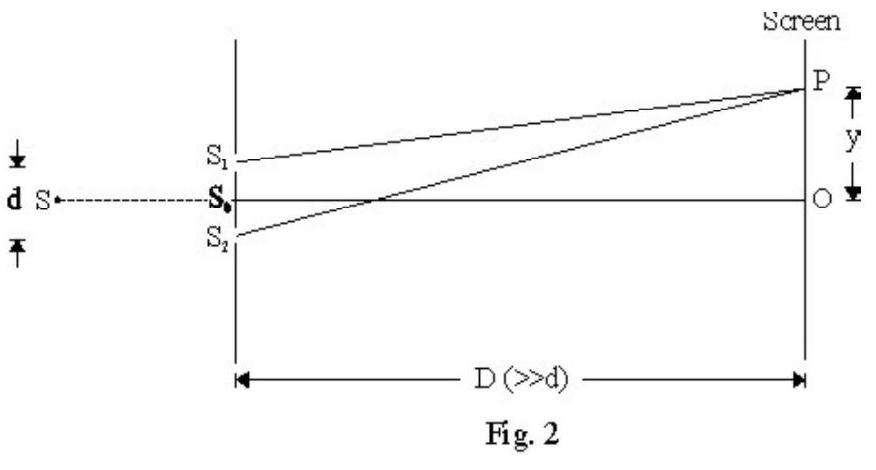
Figure- 2 shows Y.D.S experiment. is an incoherent monochromatic source. and are two identical slits placed symmetrically with respect to d. The screen is at a distance . For a point on screen.
The path of difference between the two waves at point
For constructive interference
For destructive interference
The fringe width ; is distance between any two consecutive bright or dark fringes.
is same for bright or dark fringes. does not depend on value of . All fringes are equispaced.
A program to give wings to girls students
The resultant intensity, ; at point is
is intensity of either or is the intensity of any bright fringe. All bright fringes are equi-bright and all dark fringes are equidark. There is no violation of law of conservation in interference. Energy is only redistributed.
57. In a modified Y.D.S experiment . Let be the initial path difference between the two interferring beams. For constructive interference
For destructive interference
The centeral fringe is not obtained at . The centeral fringe moves above or below depending on value of . However fringe width, , remains same.
58. When a thin film of thickness ; refractive index is introduced in the path of one of the two interferring beams; the extra path difference introduced . Let be the observed fringe shift.Then
59. Diffraction is phemomenon of bending of waves around an obstacle in their path and the penetration of waves into the region of geometrical shadow. Diffraction is easily observed with sound or water waves. Since of light is very small; to observe diffraction of light the size of obstacle should be also very small i.e. comparable to wave length of waves. All type of waves undergo diffraction.
60. In a single-slit diffraction experiment a parallel monochromatic beam is incident on a slit of widthd a fraction of ). The diffraction pattern is observed on a screen at a large distance (of the order of a meter) from the slit. The half angular width of centeral maxium, , is
The radius of centeral maximum is
61. In a diffraction pattern centeral maximum is most intense. Intensity of subsidary maxima’s decreases rapidly. The fringes observed are not equi-spaced. The number of fringes observed is small ( to 10).
62. Polarisation is the process of selecting a preferred direction of vibration and blocking all other vibrations. Only transverse waves can be polarised. Longitudinal waves cannot be polarised.
63. Light coming of a source has oscillating in all directions perpendicular to direction of wave propagation. Such waves are unpolarised. Light from sun, sodium lamp; fluroscent tube etc. is unpolarised.
64. A calcite or tourmaline crystal has the property of allowing oscillation of parallel to its axis to pass through and stop vibration of in all other directions. It is used to polariser an unpolarised beam. It is known as a polarsier. The vibration of of light emerging out of polariser are only in a direction parallel to axis of polariser. Such a beam is known as plane polarised.
65. An analyser is a quartz crystal used to find out whether light incident on it is unpolarised or plane polarised.
66. For unpolarised incident light, there is no variation in intensity of light transmitted by analyser when it (analyser) is rotated through are full circle about direction of propagation of light as axis.
67. For an incident plane polarised light; when analyser is rotated through one full circle about direction of propagation of light as axis; the intensity of transmitted light varies. In one full rotation there are two position in which intensity of transmitted light is zero.
68. An unpolarised ray of light can be polarised due to reflection. If angle of incidence equals a particular value, , the reflected beam is plane polarised. is known as polarising angle of incident. According to Brewster’s law
is refractive index of reflector.
69. Consider a plane polarised beam of intensity incident on an analyser. Let be the angle between the axis of analyser and polariser.
The intensity of light transmitted by the analyser
This is Malus law.
Average
Reflection of Light
1. A ray of light propagating along the direction is incident on a plane mirror. After reflection it moves along the direction . The angle of incident is
(1)
(2)
(3)
(4)
Show Answer
Correct answer: (1)
Solution:
Let and be angle of incidence and reflection in plane. From law of reflection, . For incident ray
For reflected ray
Difficult
Reflection of Light
2. In an experiment to determine the focal length (f) of a concave mirror, “by the u-v method”, a student places an object pin on the principal axis at a distance from the pole of the mirror. The student looks at the pin and its inverted image from a distance keeping his / her eye in line with PA. When student shifts his/her eye towards left the image appears to move to right of the object pins. This implies that
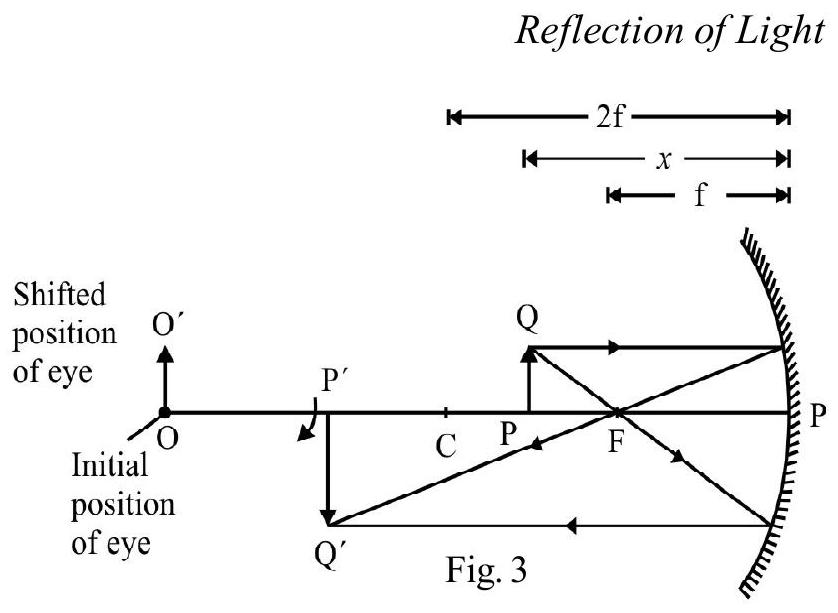
(1)
(2)
(3)
(4)
Show Answer
Correct answer: (2)
Solution:
Figure- 3 show image ’ of object lying in between and . is initial position of eye of student. is shifted position of eye. The arrow , shows the apparent direction of motion of image. These movements are in accordance with the statement of question. Hence obejct lies between F and C, i.e.
Average
Spherical Mirror
3. For the mirror formula,
Which of the following statements is correct?
(1) Formula is valid for mirros of large aperature for all position of object
(2) Formula is valid for mirrors of large aperature and small focal length
(3) Formula is valid for mirror of small aperature and objects placed at large distances in comparison to focal length
(4) Formula is valid for mirror of small aperature and object placed close to mirror
Show Answer
Correct answer: (2)
Solution:
Statement (3) is restatment of “paraxial ray assumption” used is deriving the mirror formula.
Difficult
Reflection
4. A real object is at a distance a from the focus of a convex mirror of power . The distance of the image from the mirror is
(1)
(2)
(3)
(4)
Show Answer
Correct answer: (4)
Solution:
Figure- 4 shows object , and its virtual image, ‘, formed by the convex mirror. The image lies between and . The magnitude of focal length of mirror, ; is
Let and the distance of object and image ( ) from focus of the mirror. From Newton’s formula
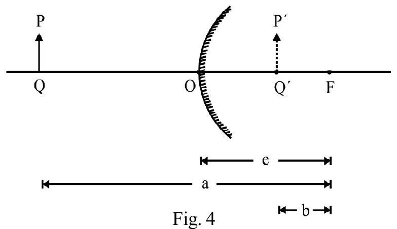
The distance of image from mirror
Average Reflection and Refraction
5. A concave mirror is placed on a horizontal table with its axis directed vertically upwards. Let be the pole and the center of curvature of mirror. A point object is placed at . The mirror forms its real image, also located at . The mirror is now filled completely with water. The image, now, would be
(1) real and remains at
(2) real and located between and
(3) virtual and located at a point between and
(4) real and located between and
Show Answer
Correct answer: (4)
Solution:
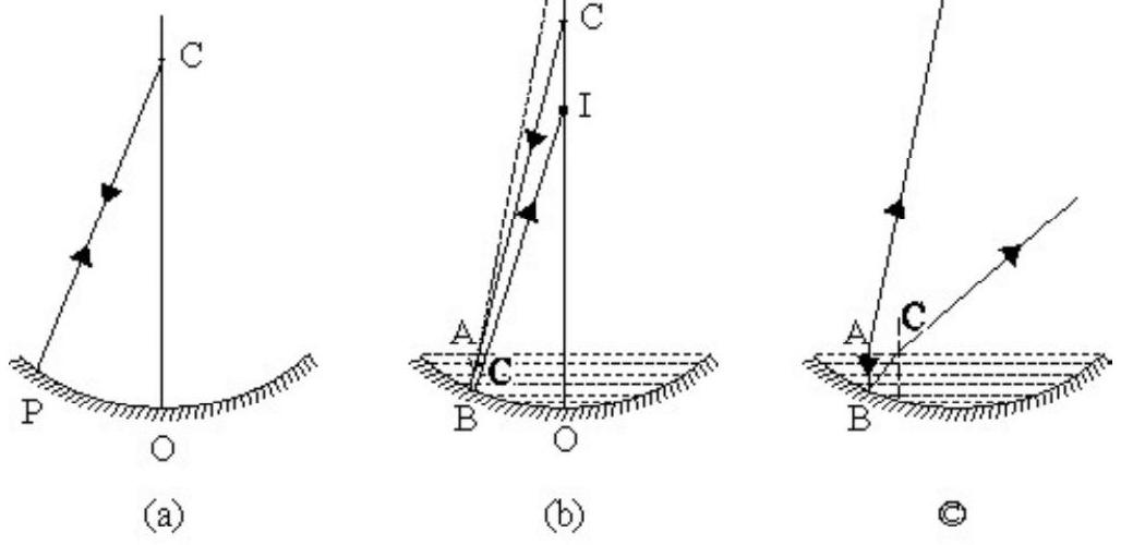
Figure- 5 (a) shows image at due to reflection from concave mirror. The ray , is, therefore, incident normally on mirror.
When mirror is filled with water; the incident ray CA first undergoes refraction at water. The refracted ray is incident on mirror. This ray is not incident normally. It undergoes reflection obeying law of reflection. The reflected ray again undergoes refraction at water surface forming its real image I that lies between and .
Difficult
Refraction of Light
6. The plane is the boundary between two transparent media. Medium 1 , with , has a
refractive index and medium 2 , with , has a refractive index . A ray of light, incident in medium 1 , given by
is incident on the plane of seperation. Its angle of incidence (i) and the angle of refraction (r), would be
(1)
(2)
(3)
(4)
Show Answer
Correct answer: (1)
Solution:
The angle of incidence (i) is given by “the direction cosine” of with the -axis; the normal to the plane of incidence. Hence is given by
Applying Snell’s law,
Difficult
Refraction
7. Speed of light , in a medium; in accordance with e.m. theory, is given by
Here and represent the relative permittivity and relative permeability of the medium.
For commonly occuring materials, and are positive numbers. Aritifically prepared materials, known as ‘meta materials’, have a negative, value of refractive index . For a ‘meta material’, the correct version of the above statement and the Figure- showing refraction, is the one given in option
(1) speed of light in meta material
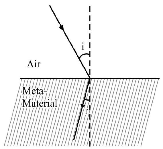
(2) speed of light in meta material
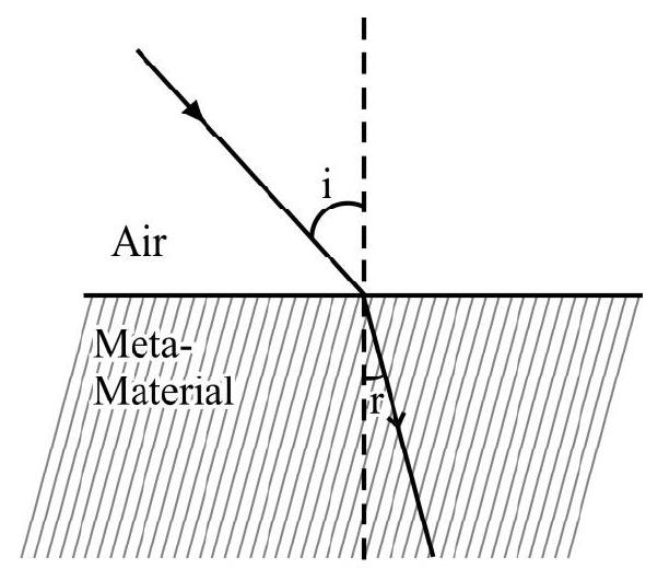
(3) V speed of light in meta material
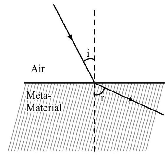
(4) speed of light in meta material
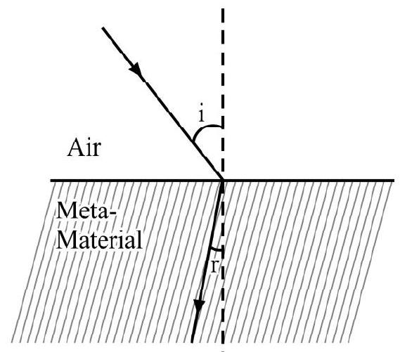
(Based on I.I.T, 2012)
Show Answer
Correct answer: (1)
Solution:
For normal materials
Here speed of light in medium. For a ‘meta-material’ since in is a negative number, would become a negative number. Therefore, we take
For a ‘meta material’, the refracted ray is on the same side of normal as the incident-ray is. Hence the figure, given in option (1) correctly shows the refraction of an incident ray, in such a material.
Easy
Refraction of Light
8. A divergent beam of light from a point source , (having a divergence angle ), falls symmetrically on a glass slab as shown in Figure- 6. The angle of incidence of the two extreme rays are equal. It the thickness of glass slab is and its refractive index is , the divergence angle of emergent beam, would be
(1) zero
(2)
(3)
(4)
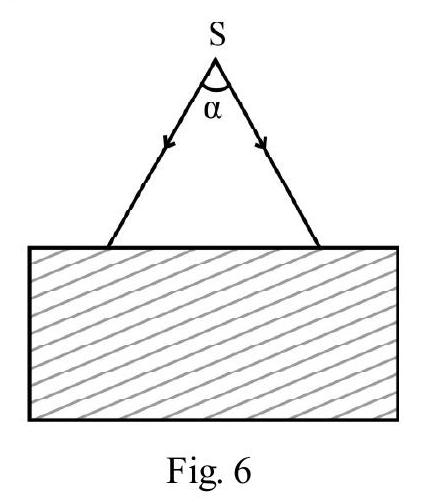
Show Answer
Correct answer: (2)
Solution:
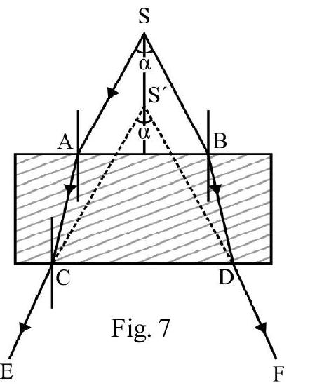
Figure- 7 show refraction, through the glass slab, for incident rays and SB. The emergent ray is parallel to and the emergent ray is parallel to SB. The emergent rays appear to diverge from point . However the angle of divergence also equals .
Difficult
Refraction of Light
9. A parallel glass slab, of thickness , has been made from a glass of refractive index . A ray of light is incident on one face at an angle of incidence of . The lateral shift of the ray, due to refraction, through the slab, is (nearly)
(1)
(2)
(3)
(4)
Show Answer
Correct answer: (2)
Solution:
Figure- 8 shows incident ray undergoing refraction through glass slab.
is the emergent ray. The lateral displacement (say).
From right angled
From right angled
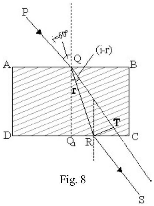
Applying Snell’s law at point Q,
or
Given . From equation (1) we have
Average
Refraction of Light
10. A ray of light is incident, from the ‘glass side’, at the glass-water interface, at an angle i. It emerges out parallel tothe surface of water as shown in the Figure- 9. The refractive index, , of glass, is

(1)
(2)
(3)
(4) 1
Show Answer
Correct answer: (2)
Solution:
Let and denote the refractive indices of glass and water, respectivly. Let rbe angle of refraction in water, for ray incident in glass at angle i. From Snell’s law,
For refraction at water-air interface; using Snell’s law, we get
From equation (1) and (2) we have
Average
Refraction of Light
11. A light beam is propagating, from region I to region IV [refer to Figure-10. The refractive indices of region I, II, III and IV are ( , and respectively. The angle of incidence, , in region , for which the beam would just miss entering region IV, is
(1)
(2)
(3)
(4)

Show Answer
Correct answer: (2)
Solution:
Figure- 11 shows the ray incident, from region , at an angle of incident . Since the incident ray at , i.e, region III just fails to enter region IV, the angle of incidence at , must equal the critical angle of incidence between regions III and IV. Hence
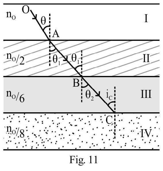
Using Snell’s law at point A and B, we have
and
Average
Refraction
12. A ray of light passes through four transparent media (with refractive indices and ) as shown in the Figure- 12. The surfaces of all media are parallel. If the emergent ray CD is parallel to the incident ray ; we must have
(1)
(2)
(3)
(4)
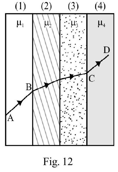
Show Answer
Correct answer: (4)
Solution:
Let be angle of incidence of ray in medium of refractive index . Let, be angle of refraction in medium 2. From Snell’s law
The angle of incidence, in medium is . Let angle of refraction, in medium 3 be . Then
The angle of incidence in is and angle of emergence of ray CD in medium is (because CD is parallel to ). Therefore
From equation (1), (2) and (3) we have
Difficult
Refraction of Light
13. A parallel glass slab, of thickness , has a uniformly varynig refractive index. The media, on the two sides of slab, have ref ractive indices and , respectively. A ray, in medium of refractive index , enters the slab, at an angle of incidence . After passing through the slab, it emerges out in the medium of refractive index . The angle of emergence is . Which of the following statements is incorrect?
(1) ; if ; irrespective of the nature of variation of the refractive index of the slab.
(2) depends on the nature of variation of refractive index of slab
(3)
(4) is more than if
Show Answer
Correct answer: (2)
Solution:
Let and be the refractive index of the glass layers, and , respectively. We can put
( constant rate of change of refractive index)
For refraction at layer
For adjacent layers, we would have
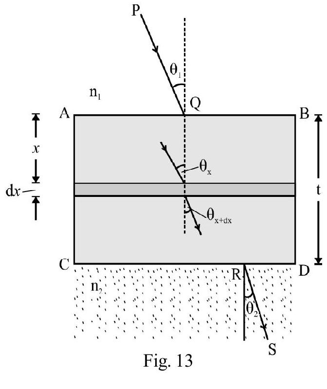
For refraction, at the layer , into medium of refractive index , we have
From these equations, we get
and, therefore,
Hence and depend on , and not on the (uniform) nature of variation of the refractive index of the slab.
Thus, out of the given statements, only statement (2) is incorrect.
Difficult
Refraction
14. A transparent slab of thickness has a refractive index that increases with . Here is the vertical (depth) distance inside slab; measured from top. The slab is placed between two media having uniform refractive index, and respectively. A ray of light is incident, at an angle , from medium 1 , and emerges out, in medium 2; with refraction angle , and with a later displacement . Which of the following statements is incorrect?
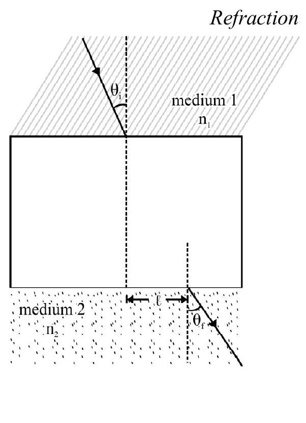
(1) independent of
(2)
(3)
(4) depends on
Show Answer
Correct answer: (2)
Solution:
The lateral displacement depends on (i) and (ii) but is indepdent of (z). The only incorrect statement is
Difficult
Total Internal Reflection
15. A glass slab, of thickness , has a refractive index . A point source is kept at the bottom of the slab. The fraction of light, emitted by , that emerges out of the upper face of slab, is
(1) 0.5
(2)
(3)
(4) 0.25
Show Answer
Correct answer: (3)
Solution:
Figure- 15 shows that only those incident rays from , that lie within the cone , emerge out of the upper surface of glass. Also
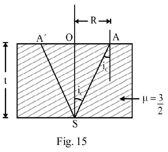
The area S; from which light emerges out is
The total light, emitted by , gets spread over the surface of a sphere of radius R, i.e., . Therefore Fraction of total light (emitted by the source ) that passes out of the slab, is
Average
Real and Apparent Depth / Height
16. A ball is dropped, from a height of , above the surface of water in a lake. The refractive index of water is . A fish inside the lake; in the line of fall of the ball, is looking at the ball. At the instant when the ball is above the surface, the fish would observe the speed of the ball as
(1)
(2)
(3)
(4)
Show Answer
Correct answer: (3)
Solution:
In the Figure- 16, B is the actual instantaneous position of the ball when it is at a height y above the surface of water. is the apparent position of the ball, as seen by the fish. The instantaneous apparent height . Let be the refractive index of water. We know that
The apparent instantaneous speed of ball
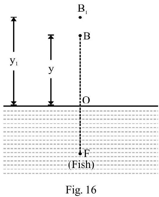
Difficult
Reflection and Refraction
17. A container is filled with water up to a height of . A concave mirror is placed above the surface of water, as shown in the Figure- 17. The image, of an object , at the bottom gets formed at below the water level. The focal length of the mirror is (approximately)
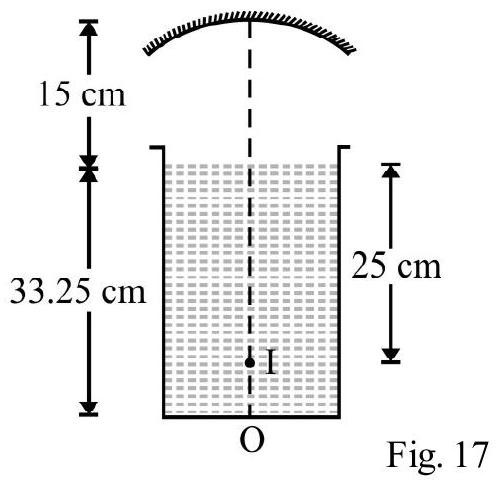
(1)
(2)
(3)
(4)
Show Answer
Correct answer: (3)
Solution:
Due to refraction at water, the object, at , appears to be at a distance of , below the top level of water. Hence the object distance for mirror
For concave mirror
However, the reflected rays again undergoes refraction at surface of water. The apparent depth of the image, below the water level in tank, is and is given to be . Therefore,
Using mirror formula, we now get
Focal length of the mirror
East
Refraction
18. White light is incident on the interface of glass-air, as shown in the Figure- 18. If green light is just totally internally reflected, then the emerging rays, in air would have in them, the colours
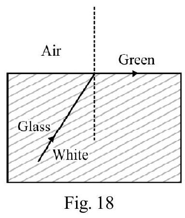
(1) yellow, orange, red
(2) violet, indigo, blue
(3) all seven colours of white light
(4) all the other six colours of white light (exept green)
(I.I.T 2004)
Show Answer
Correct answer: (1)
Solution:
Let be the refractive index of glass for light of wave length . We know . Also,
where is a constant
The angle of incidence, for green colour, equals the critical angle. For light of more than that of the green colour, the critical angle would be more than that for green. Only these colours would not undergo T.I.R and would emerge out. Therefore, yellow, orange and red (having ) would emerge out.
Average
Refraction of Light
19. A ray of light, travelling in water, is incident on its surface open to air. The angle of incidence is less than the critical angle of incidence. Then there will be
(1) only a reflected ray and no refracted ray
(2) only a refracted ray and no reflected ray
(3) a reflected and a refracted ray and the angle, between them, is less than
(4) a reflected and a refracted ray and the angle, between them, is greater than 2 )
Show Answer
Correct answer: (3)
Solution:
Since angle of incidence is less than critical angle, we will have both reflected and refracted rays. In Figure- 19, AO is the incident ray. and are the reflected and refracted rays. The angle of refraction
.
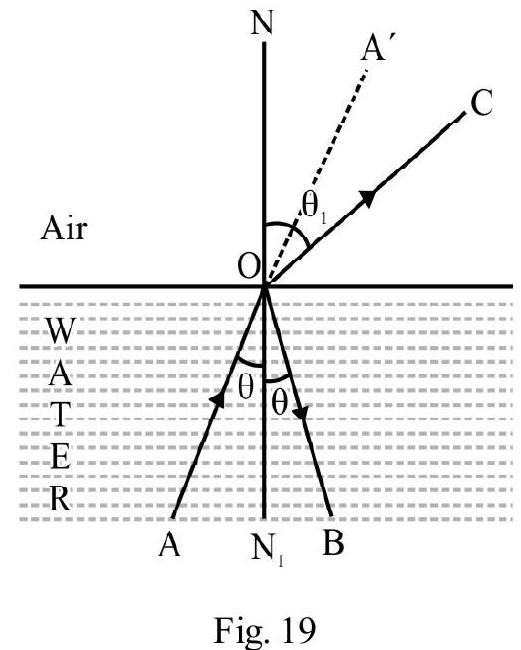
[Because light is going from a denser to a rarer medium]. Also
The angle between reflected and refracted ray
As is less than .
Average
Refraction Through a Prism
20. In an experiment to determine the refractive index of glass of a prism; the (i) vs. ( ) graph is plotted. It was found that a ray incident, at an angle of , suffers a deviation of and it emerges at an angle of . Which is the closest possible value of ?
(1) 1.5
(2) 1.6
(3) 1.7
(4) 1.8
Show Answer
Correct answer: (1)
Solution:
For a prism of refracting angle ; a ray incident at an angle ; emerges out at angle . The deviation, , is
Given
or
The refractive index of prism is given by
Assuming that incident ray has undergone minimum deviation we have
The deviation, for the given incident ray, may not be the minimum value of deviation. We can, therefore, only say that is close to 1.5 .
Easy
Refraction Through a Prism
21. A ray of light is incident normally on one face of a prism of refracting angle and refractive index . The angle of deviation is
(1)
(2)
(3)
(4) zero
Show Answer
Correct answer: (3)
Solution:
Figure- 20 shows prism . Ray is incident normally on its face PQ. It passes straight into the prism. The ray BC, inside the prism, is incident on face PR at an angle of incidence . Let be the angle of refraction. From Snell’s law:
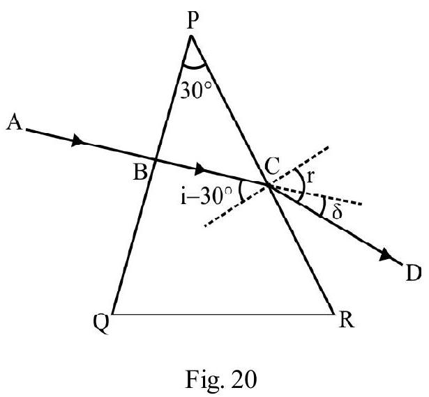
The angle of deviation
Easy
Refraction Through a Prism
22. The graph between angle of deviation ( ) an angle of incidence (i) for a triangular prism is
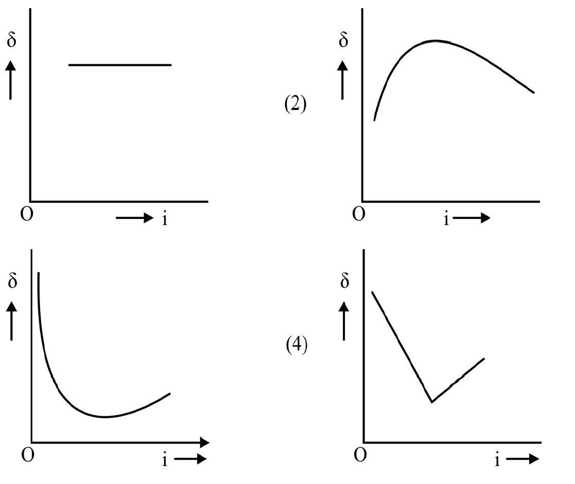
Show Answer
Correct answer: (3)
Solution:
Angle of deviation ( ) for a given prism depends on angle of incidence (i). Starting from small values of , decreases as i increases. It accquires a minimum value for a particular angle of incidence; after that it starts increasing as i increases further. This is shown correctly in option 3 .
Average
Refraction Through a Prism
23. Beams of red and violet colour, are made to pass through a prism of angle , one by one and are the angles of refraction, when and are the angles of minimum deviation, in the two caess. Then
(1)
(2)
(3)
(4)
Show Answer
Correct answer: (4)
Solution:
Under minimum deviation conditions
Therefore, for both red and violet rays when they are undergoing minimum deviation. The refractive index of prism is
We know that ; therefore angle of minimum deviotion for violet colour is more than for red colour i.e., .
Average
Total Internal Reflection
24. A ray of green light is incident from water to air; (at the air-water interface) at the critical angle of incidence. Select the correct statement:
(1) The entire spectrum of visible light will come out at an angle of to the normal
(2) The part of the spectrum of visible light, for which the frequency in less that of green light, will come out in air
(3) The spectrum of visible light, whose frequency is more than that of green light will come out in air.
(4) The entire spectrum of visible light will come out of water at different angles to the normal
Show Answer
Correct answer: (2)
Solution:
Let be critical angle of incidence for green light at the water air interface. Then
For . Refractive index decreases as increases. From for ; critical angle of incidence increases. These rays would not undergo total internal reflection at . These colours would, therefore, emerge out of the water-air, interface, into the air.
Average
Refraction Through a Prism
25. is an isoceless prism of angle and has a refractive index of 1.44. Two parallel rays and undergo refraction through this prism. The rays, emerging from the opposite face
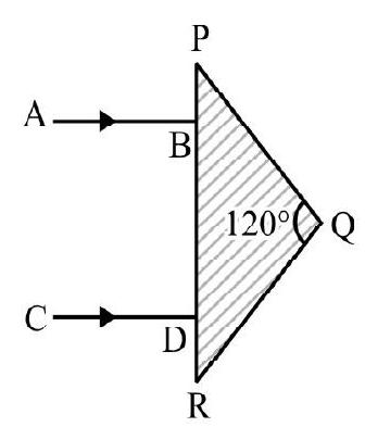
(1) are parallel to one another
(2) are diverging
(3) make an angle of with each other
(4) make as angle of with each other
Show Answer
Correct answer: (3)
Solution:
Figure- 23 shows the refraction of rays and through prism.
Applying Snell’s law at point E.
The angle of deviation at is
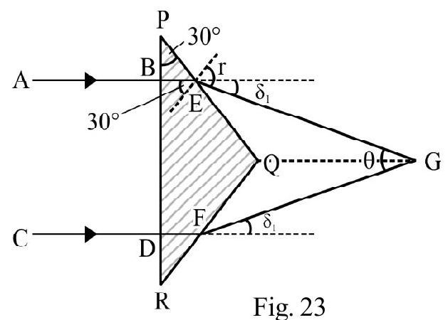
Similarly, the ray , also gets deviated through an angle , at the point
The angle between the two emergent rays is
Average
Total Internal Reflection
26. A parallel beam of light is incident, from air, at an angle , on the side of a right angled prism of refractive index . Light undergoes total internal reflection in the prism, at the face , when has a minimum value of . The angle, , of the prism is
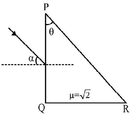
Figure- 24
(1)
(2)
(3)
(4)
Show Answer
Correct answer: (1)
Solution:
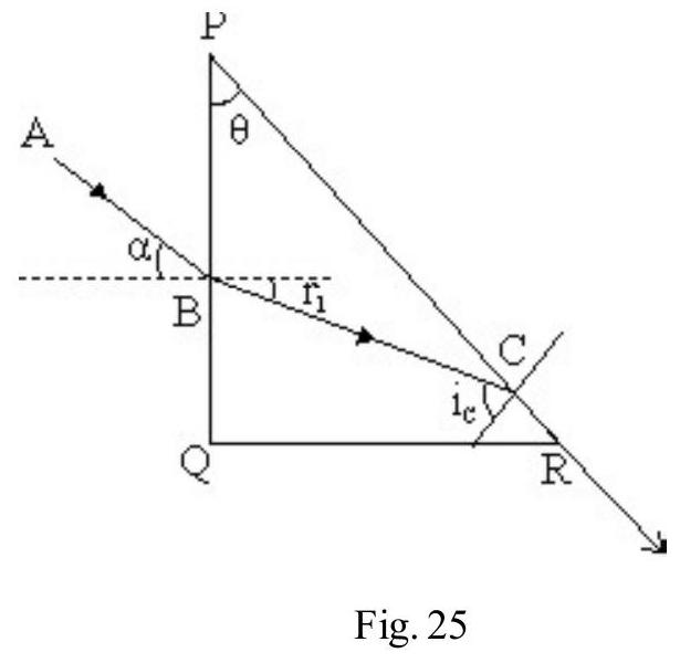
Figure- 25 shows total internal reflection occuring at the face PR. Applying Snell’s law at B
Given ; therefore
or
Let be the critical angle of incidence inside glass. Then
From ; we have
Difficult
Refraction Through a Prism
27. is a prims of refracting angle and refractive index . The face is coated with a film of a transparent material of refractive index 2.2. An incident ray undergoes refraction inside the prism, but does not undergo any deviation at the film. If the net deviation is , the angle of incidence, , is
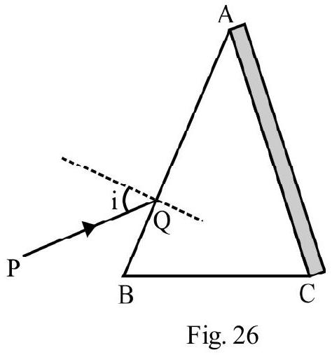
(1)
(2)
(3)
(4)
Show Answer
Correct answer: (3)
Solution:
Figure- 27 shows the path of the incident ray PQ. QR falls normally on the film on face AC. There is no deviation due to film. The deviation is only due to refraction on face of prism . Given
Applying Snell’s law, at point Q, we get
This relation is satisfied if .
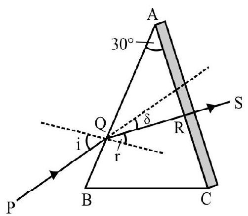
Average
Total Internal Reflection
28. A right angled prism is to be made by selecting an appropriate material and angles and as shown in the Figure- 28. A ray , incident normally on face , is to emerge parallel to itself, after two internal reflections, as ray RS. The minimum value of of material, for this requirement, is
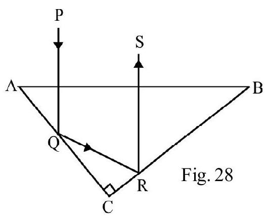
(1)
(2)
(3)
(4)
Show Answer
Correct answer: (1)
Solution:
Total internal reflection must take place at points Q and R as shown in Figure- 29. Angle of incidence, at Q, equals angle and angle of incidence, at , equals angle . Let be the critical angle of incidence. Then
Also, (given)
It follows that, , for the material of prism is minimum if and this is also the value of the critical angle. Hence
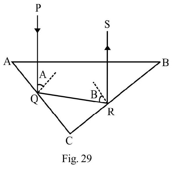
Average
Total Internal Reflection
29. A right angle prism is made of a material of refractive index 1.67. AB is ray incident normally on face as shown in Figure- 30. Which of the following statements is correct?
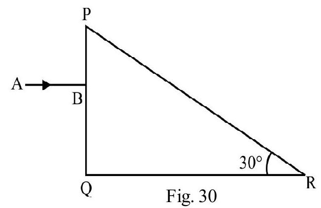
(1) AB emerges out of face PR of prism
(2) AB undergoes a deviation of on face PR of prism
(3) Ray , emerges out of face at an angle of emergence of
(4) Ray emerges out of face QR normally
Show Answer
Correct answer: (2)
Solution:
The critical angle of incidence, , inside the prism is given by
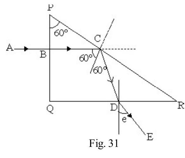
The angle of incidence on face PR is . This is more than ; hence T.I.R occurs at face PR.
The angle of deviation
The totally reflected ray , is incident at , at point , on face . The angle emergence, , is given by is
Hence statements (3) and (4) are seen to be incorrect. It is only statement (2) that is correct.
Difficult
Refraction Through a Prism
30. A monochromatic light is incident on a glass prism of angle . The refractive index of the material of the prism is . A ray is incident at an angle on the face of the prism. It can emerges out of the face of prism provided
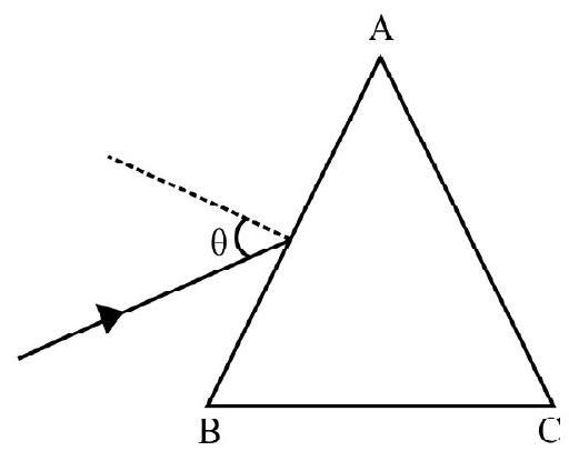
(1)
(2)
(3)
(4)
(I.I.T Main 2015)
Show Answer
Correct answer: (4)
Solution:
Figure- 33 shows the ray incident on face of the prism. Let be angle of refraction at . From Snell’s law
The refracted ray is incident on face at an angle . The ray would emerge out of face if where is the critical angle of incidence (from glass to air). Also
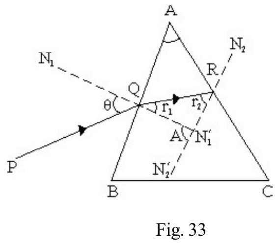
Now.
For ray to emerge out, we must have
Difficult
Total Internal Reflection
31. A light ray, travelling in glass medium, is incident on the glass-air interface at an angle . The reflected (R) and the transmitted (T) intensities, are both plotted, as functions of . The correct graph is the graph labelled as
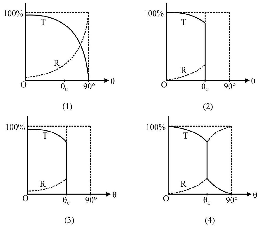
(I.I.T 2011)
Show Answer
Correct answer: (3)
Solution:
At . However, is not zero and is not 1 . As increases, from to the critical angle ; decreases and increases. For , upto ; there is no transmitted beam; therefore, . Over this range, due to T.I.R, of incident light is reflected back, i.e., .
These variation are correctly shown only in graph (3).
Average
Refraction Through a Prism
32. and are two prisms joined togetheras shown in Figure- and are the refractive indices of the material of the two prisms. Given:
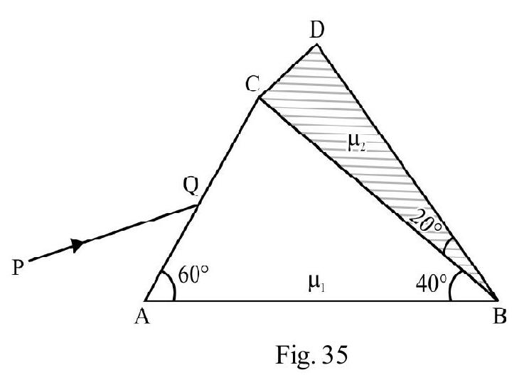
where is in . is an incident ray, incident on face . There is no bending of ray inside the prisms, on the face , the common face of the two prisms. The wavlength, , of the incident ray, , must be
(1)
(2)
(3)
(4)
Show Answer
Correct answer: (3)
Solution:
For no deviation of ray incident on ; (irrespective of the angle of incidence on ), we must have . Therefore
This gives
Average
Refraction Through a Prism
33. Three prisms, made from materials of, refractive indices and , are arranged as shown in Figure- 36. An incident ray, AB, emerges out as EF, following the path shown in the figure. Then the rays undergo minimum deviation in
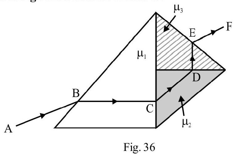
(1) prism, , only
(2) prism and prism but not in prism
(3) prism only
(4) in all the three prims
Show Answer
Correct answer: (4)
Solution:
The path of rays and , inside the respective prisms, are parallel to the base of prism considered. Hence minimum deviation occurs inside all the three prisms.
Average
Refraction and T.I.R
34. PQR is a right angled issoceless prism of a material of refractive index . It is placed inside a parallel slab, made of two parts, having refractive indices and , as shown in Figure- 37. An incident ray AB follows the path shown. We must then have
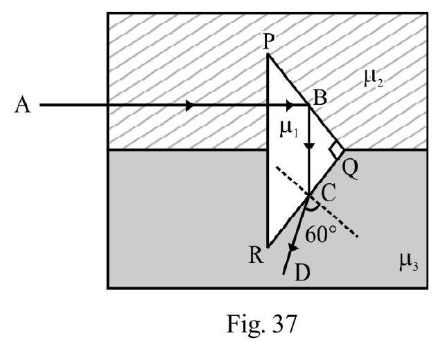
(1)
(2)
(3)
(4)
Show Answer
Correct answer: (1)
Solution:
Total internal reflection occurs at point B. Therefore and . Hence . Therefore,
The ray is incident on face at an angle of . It emerges out at an angle of refraction of . Therefore,
Average
Total Internal Reflection
35. A point source is placed at the bottom of a transparent block, of height , and refractive index 2.72. It is immersed in a liquid of lower refractive index as shown in Figure- 38. It is found that the light, emerging from block to liquid, forms a circular bright spot of diameter on top of the block. The refractive index of the liquid, is
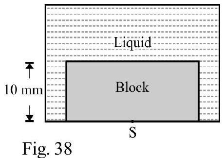
(1) 1.21
(2) 1.30
(3) 1.36
(4) 1.42
Show Answer
Correct answer: (3)
Solution:
In Figure- is the diameter of bright circular spot. For incident ray ; total internal reflection occurs at . The angle of incidence . We are given that . Let be the refractive index of the liquid. From Snell’s law, we have
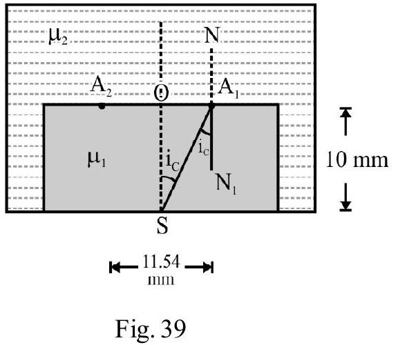
Average
Refraction Through a Prism
36. Three identical equilateral prisms and are arranged as shown in Figure- 40. An incident ray passes through all three and undergoes deviations and respectively, in each of the three prisms. is the net deviation, due to the whole arrangement. Then
(1) say) and
(2) say) and
(3)
(4)
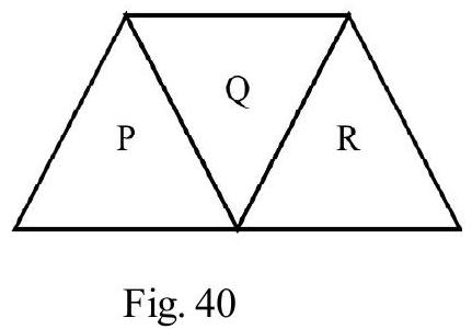
Show Answer
Correct answer: (2)
Solution:
Since the three prisms are equilateral and identical; we would have
However is in a direction opposite to . Hence the net deviation.
Difficult
Passing of Light Through a Prism
37. A ray of light is incident on an equilateral prism of refarctive index . It passes through the prism as shown in Figure- 41. CDE is a second prism exactly identical to prism . The emergent ray, from prism , is required undergo minimum deviation in prism CDE. For this the prism CDE should be rotated through
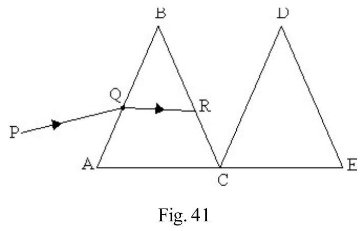
(1) , clockwise
(2) , clockwise
(3) , anticlockwise
(4) , anticlockwise
Show Answer
Correct answer: (3)
Solution:
The path, , of ray inside prism , is parallel to base of prism. The incident ray is therefore, undergoing minimum deviation in this prism. Let and denote angle of incidence and refraction, at the face on . For minimum deviation,
From Snell’s law
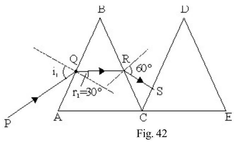
The ray emerges out of prism from face ; at angle of emergence . It is, therefore, incident normally, on face , of prism CDE. If this ray is to undergo minimum deviation inside CDE, angle of incidence of RS, on CD, should be again . This will be so if prism CDE is rotated, through , in the anticlockwise direction.
Average
Total Internal Reflection
38. PQR is a prism of angle . The refractive index, , of the prism is given by
is wave - length of incident light.
is a ray of while ray has . The two rays are incident as shown in Figure- 43. Which of the following statements is correct?
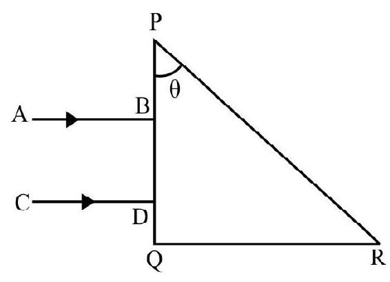
(1) Both rays and , emerge out of face
(2) Ray AB does not emerge out, but ray CD emerges out, from face PR
(3) Ray AB emerges out, but ray CD does not emerge out of face PR
(4) Neither ray AB nor ray CD, emerges out of face PR
Show Answer
Correct answer: (3)
Solution:
Let and the, respective, refractive indices of the prism for rays and . Then
The angle of incidence of both rays on face PR is . The critical angle, and , for wavelengths and , are
Therefore, ray undergoes T.I. R on face and does not emerge out. For ray , angle of incidence is less than the critical angle . This ray emerges out of race .
Average
Refraction Through Prism
39. is an isoceless right angled prism, made from a material of refractive index . It is placed inside a block made from a material of refractive index . The block itself is inside a material of refractive index . Figure- 44 shows the path of an incident ray through the arrangement. Then
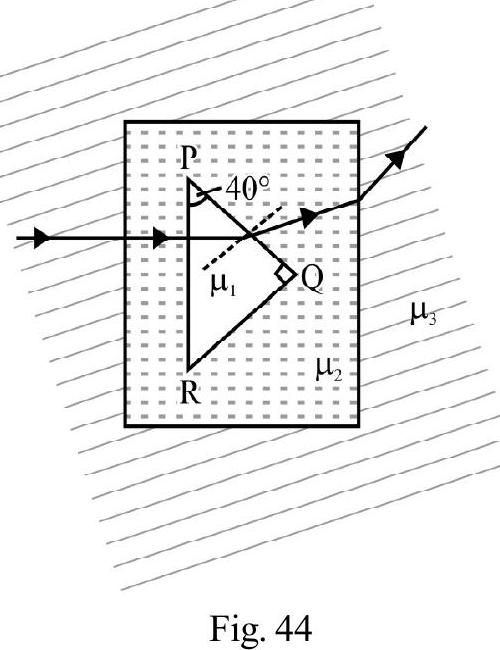
(1)
(2)
(3)
(4)
Show Answer
Correct answer: (1)
Solution:
On face PQ, of prism, the angle of incidence . The ray emerges out. Therefore . The ray also bends towards normal. Therefore . From the side of the rectangular block the ray emerges out and bends away from normal. Therefore, .
Average
Total Internal Reflection
40. and are two parallel slabs of materials of refractive indices and respectively. The medium between the slabs has a refractive index as shown in Figure- 45. The minimum angle of incidence of ray , so that T.I.R occurs at both the slabs, is
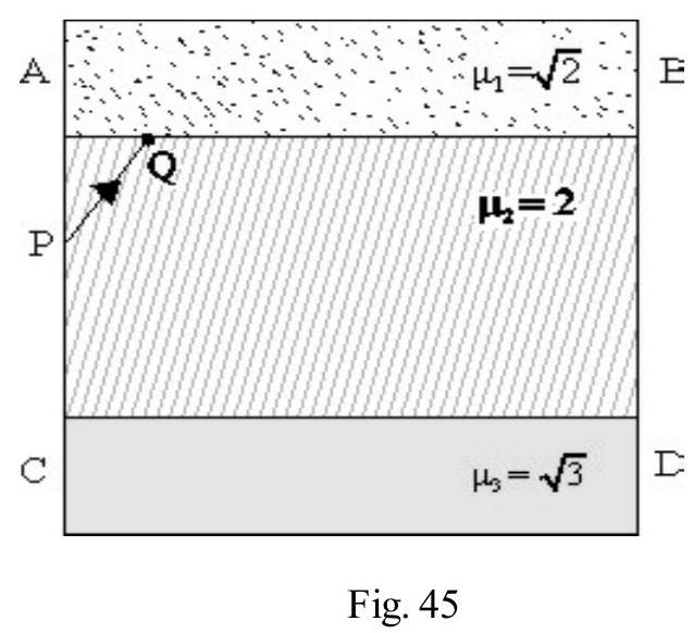
(2)
(2)
(3)
(4)
Show Answer
Correct answer: (3)
Solution:
Let and be the critical angles of incidence for slabs and , respectively. Then,
Similarly,
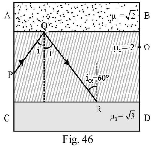
Let be the angle of incidence at so that T.I.R occurs at . The angle of incidence on equals i. For T.I.R to occur at .
Hence the minimum value of , at , must be .
Difficult
Refraction of Light
41. A glass plate, of thickness , is made of a material of refractive . A ray of light is incident on one face at an angle of incidence equal to the critical angle of incidence, for the glassair interface. The lateral displacement, of the ray, as it emerges out of the glass plate, is given by
(1)
(2)
(3)
(4)
Show Answer
Correct answer: (1)
Solution:
The angle of incidence, , is
Let be angle of refraction into glass plate. From Snell’s law,
The lateral displacement, , is given by
Now,
Substituting these values, in aligned (3) and simplifying, we get
Average
Refraction of Light
42. A monochromatic light ray, , is incident on face , near the vertex, , at an angle of , as shown in Figure- 47. Refractive index of the material is . Which of the following statements is incorrect?
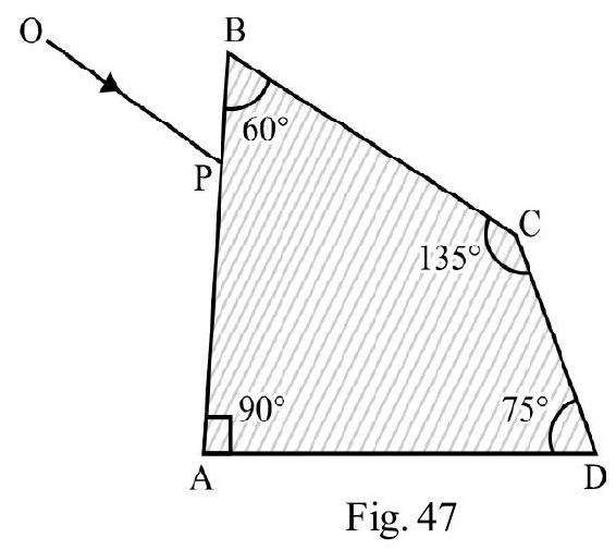
(1) The incident ray gets totally internally reflected at face CD
(2) The ray emerges out of face
(3) The angle between the incident ray and the emergent ray is
(4) The angle between the incident ray and the emergent ray is
Show Answer
Correct answer: (4)
Solution:
Figure- 48 shows the path of the incident ray inside block . For refraction at
The critical angle of incidence for air - material of , interface is
The angle of incidence, at , is . This is more than ; therefore T.I.R, occurs at Q. For ray incident at point R, angle of incidence . This is less than ; the ray, therefore, emerges out of face AD. Let be angle of emergence. From Snell’s law

The angle between the incident ray OP and emergent ray RS is .
Hence only statement (4) is an incorrect statement.
Difficult
Refraction Through a Prism
43. and are two prisms joined together as shown in Figure- 49 Given
and
( is in nanometer)
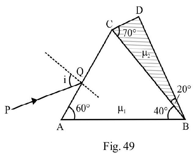
is an incident ray. It undergoes minimum deviation through the combination, suffereing no deviation at . The wave length, , and the angle of incidence of ray, PQ, are equal, respectively, to
(1)
(2)
(3)
(4)
Show Answer
Correct answer: (4)
Solution:
The will be no deviation at face it ; i.e., if
This gives
For ; the given arrangement is a part of a truncated prism of angle as shown in Figure- 50. Also .
[Value of is obtained by putting in the expression for either or ]. For minimum deviation the angle of refraction , at face , is given by
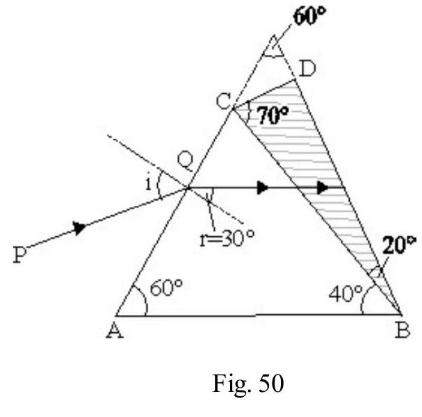
Applying Snell’s law at point Q, we have
(1)
Difficult
Dispersion Through a Prism
44. A prism , of angle , is made from a material of refractive index 1.54 and dispersive power 0.05 . It is combined with another prism of angle . The refractive index and dispersive power of material of prism are 1.72 and 0.06 , respectively. There is no net deviation due to combination, but there is a net angular dispersion, . Then
(1)
(2)
(3)
(4)
Show Answer
Correct answer: (3)
Solution:
Let and denote angle of prism; refractive index and dispersive power for prism P. and are the corresponding quantities for prism Q. The combination produces not net deviation; therefore
Negative sign of of indicates that the base of P and Q are oppositely directed to each other. Then net angular dispersion, ; is
Average
Refraction at a Spherical Surface
45. A spherical glass surface, of radius of curvature , seperates air (refractive index 1.0) from glass (refractive index 1.5). The centre of curvature of the glass surface lies in glass. A point object, , placed in air, is found to form a real image, , in the glass. The line cuts the surface at and . The distance, , is
(1)
(2)
(3)
(4)
Show Answer
Correct answer: (1)
Solution:
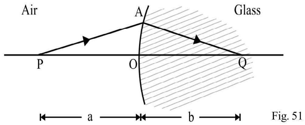
Figure- 51 shows the object , and its real image, , formed inside the glass. Let and be the object and image distances. Given . Therefore,
Using refraction formula ; we have
Difficult
Refraction at a Sperical Surface
46. A transparent thin film, of uniform thickness and refractive index , is coated on the convex spherical surface (of radius ), at the one end of a long solid glass cylinder, of refractive index, , as shown in Figure- 52. Rays of light, parallel to the axis of cylinder, going through the film, from air to glass, get focused at a distance (the opposite way) , from the film; while the rays going from glass to air, get focused out a distance from the film. We would then have:
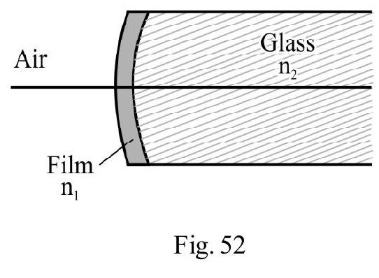
(1)
(2)
(3)
(4)
Show Answer
Correct answer: (2)
Solution:
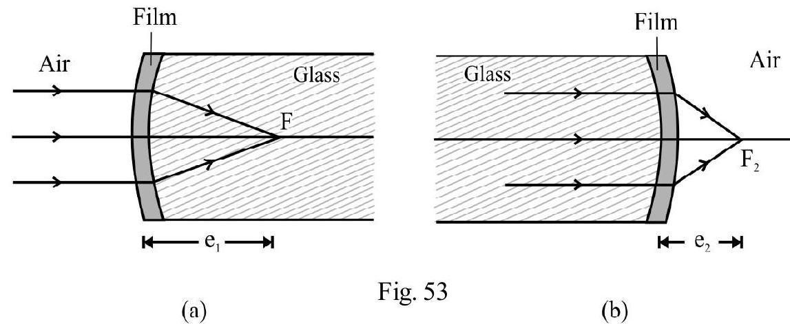
Let , be the radius of each surface of film, of thickness . The focal length, , of the thin film, according to lens maker’s formula, is
The spherical film, therefore, behaves like a parallel slab; hence there is no deviation in a ray due to its passage through the film. Figure- 53 (a) shows parallel rays, going from air, getting focused at , inside the glass. For refraction, from film to glass, we have
Using the refraction formula, at a spherical surface;
We get
Figure- 53 (b)shows the parallel rays, going from glass to air. Now
Using the refraction formula:
Difficult
Refraction a Spherical Surface
47. A quarter cylinder, of radius and refractive index 1.5 , is placed on a table. A point object, , is kept at a distance, , from it as shown in Figure- 54. The ray, after refraction through the cylindrical part, emerges parallel to the table, as shown in Figure- 54. Then
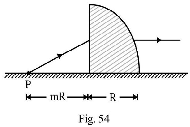
(1)
(2)
(3)
(4)
Show Answer
Correct answer: (2)
Solution:
Figure- 55 shows the refraction of the incident ray PQ; on the plane surface . The refracted ray, , inside the glass appears to come from . For refraction at this plane surface, we have
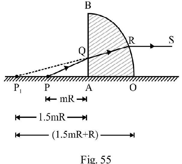
The ray is incident inside the glass on the curved surface, . The emergent ray RS is parallel to the table. For refraction at this spherical surface, we have, and . Also ’ ’ needs to be taken with a negative sign, as per the sign convention. Using refraction formula
Difficult
Refraction at Spherical Surface
48. Two glass rods; and refractive index ) have one of their ends as convex surface of radius of curvature, . They are placed with the curved surfaces, at a distance , as shown in Figure- 56. When a point object, , is placed inside , on their common axis, at distance of from the curved surface, the light rays emerging from it, are formed to be parallel to the axis inside . The distance ’ ’ equals
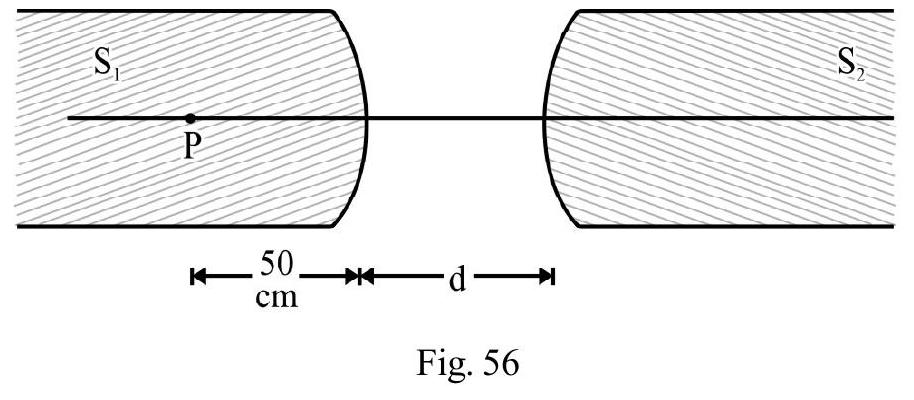
(1)
(2)
(3)
(4)
Show Answer
Correct answer: (2)
Solution:
For refraction of light, at the curved surface of rod , we have
From refraction formula, we get
Since is positive, the image , formed by , is real as shown in the Figure- 57. acts as the object for rod . For refraction, at the curved surface of , we have
Using refraction formula, we get
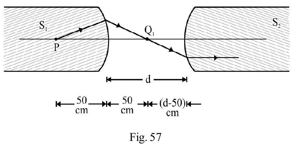
Difficult
Refracted a Spherical Surface
49. A cylinderical rod of length is curved at one end. The rod is divided into two equal parts as shown in Figure- 58. A small dot, at the mid-point , is viewed from the plane, and the curved side, one by one. The position of image, from the respective surface used, is found to be the same. The radius of curvature of curved surface equals . Then the refractive index, , of the right half of the cylindrical rod, is
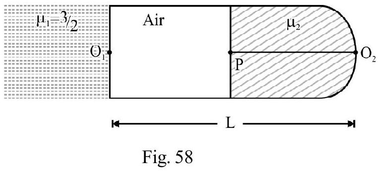
(1) 1.4
(2) 1.5
(3) 2.0
(4) 3.0
Show Answer
Correct answer: (4)
Solution:
In Figure- 59, is the position of eye when the object is being viewed from the plane surface of the rod. Let be the apparent position of the image. Then
is position of eye when is viewed from the curved surface. For curved surface; the image is again getting formed at . Hence
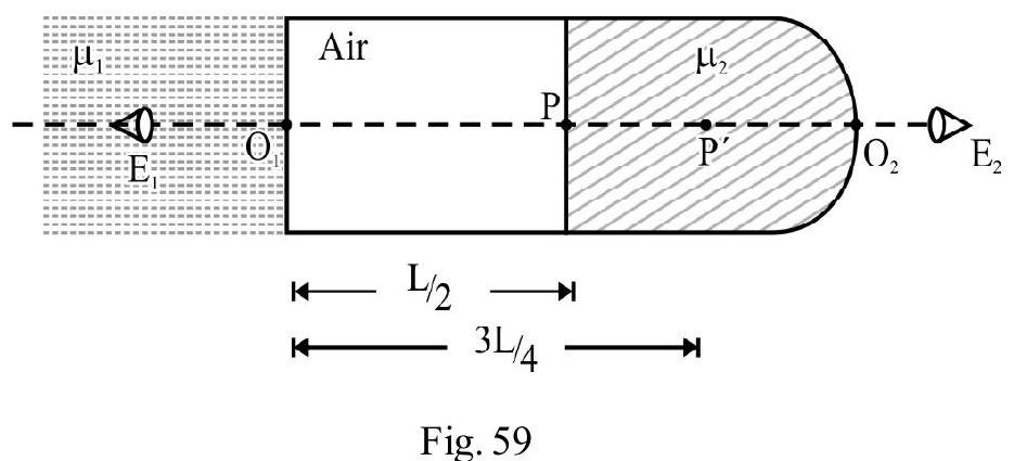
From refraction formula, for a spherical surface, we get
Average
Lenses
50. A spherical lens forms an image, twice the length of the object, on a screen. The distance between the object and the screen is . The power of the lens, is (nearly)
(1)
(2)
(3)
(4)
Show Answer
Solution:
Let and the distance of the distance of the object and screen from the lens. Since image is projected on the screen; it is real and, therefore, inverted. The magnification
The distance between screen and object (Given)
From equations (1) and (2) we have
?
Using lens formula, we get
The power of lens
Difficult
Lens
51. For a given lens, the graph, between object position, , and the image position, , is shown in Figure- 60. The focal length of the lens (in cm) is
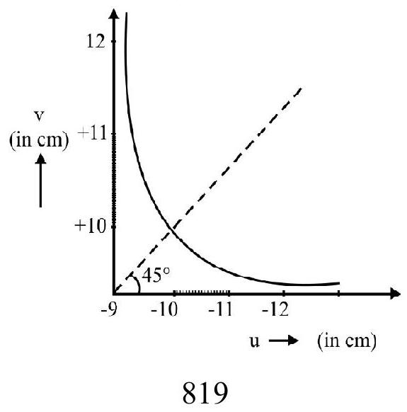
(1)
(2)
(3)
(4)
(I.I.T 2006)
Show Answer
Correct answer: (2)
Solution:
From graph, for . The focal length, , is given by
Also, ;
Now
Differentiating, we get
Therefore, the focal length, , is
Easy
Lens & Mirror
52. In Figure- 61 (a) and (b), the same object, PQ, placed, in front of a convex lens and a concave mirror, one by one, forms the image . Which of the following statements, for the position of the object , is correct?
|
Lens (L) |
Mirror (M) |
| (1) |
In between F and 2F |
Beyond C |
| (2) |
Beyond F |
In between F and C |
| (3) |
In between F and 2F |
In between F and C |
| (4) |
Beyond 2F |
In between F and C |
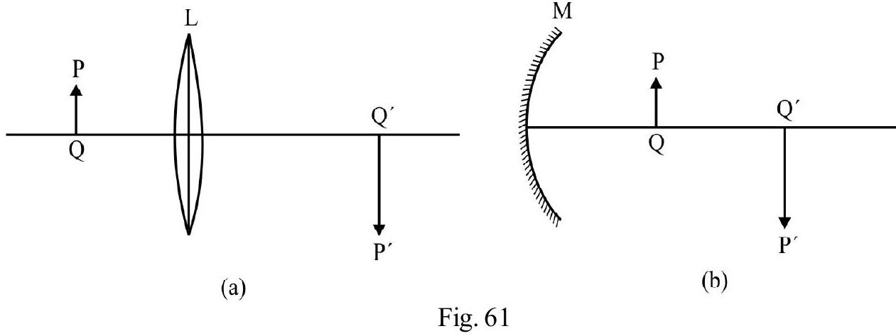
Show Answer
Correct answer: (3)
Solution:
Both the convex lens and the concave mirror form a real, inverted and enlarged image, when the object is placed in between their and points for the lens and between and points for the mirror.
Average
Refraction
53. The focal length, of a thin biconvex lens is . When an object is moved from a distance of in front of it to , the magnification of its image changes is to . The ratio is
(1) 4
(2) 6
(3) 1
(4) 3
(I.I.T 2010)
Show Answer
Correct answer: (2)
Solution:
For the first position of the object, let us calculate . Here
. Using lens formule , we have
or
The magnification is
Let us now calculate magnification for the second position of object. We have
The magnification is
Hence option(2) is correct
Easy
Lenses
54. A convex lens has a circular aperture of radius and focal length . The lens form a real image of on object. Let and I denote the position and intensity of image formed. The central part, of the lens, of radius is now painted black. Let and denote the position and intensity of image formed now. We would than have
(1)
(2)
(3)
(4)
Show Answer
Correct answer: (4)
Solution:
Painting the central part, of radius , does not change the focal length of the lens. Hence . The area of the aperture of the lens from which light passes, when central part has been painted black, is now A. The intensity , of the image, is therefore of its earlier value, i.e., .
Difficult
Lenses
55. An equiconvex lens has surfaces of radius of curvature each. It is made of two parts as shown in Figure- 62. An object is kept at a distance of from the lens. Which of the
following statements is correct?
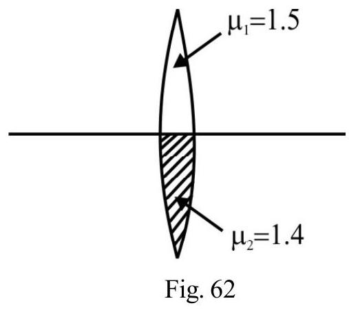
(1) There is one image at a distance of only.
(2) There is one image at a distance of only.
(3) There is one image at a distance of and another image that away from the first image.
(4) There are two images that are away from each other.
Show Answer
Correct answer: (4)
Solution:
Let and respectively be the focal length of the two parts of lens, made from material of and . Then from Lens Maker’s formula,
For both the parts of lens, of focal length and . Le and be the position of the image due to two parts of the lenser. Then
The distance between the two images
Average
Lens
56. A thin convex lens made from crown glass has a focal length . When immersed (one by one) in two different liquids, having refractive indices and ; it has focal length and , respectively. The correct relation, between the three lengths, is
(1)
(2) becomes negative
(3) ; and becomes negative
(4) and both become negative
(I.I.T Mains 2014)
Show Answer
Correct answer: (2)
Solution:
From lens maker’s formula
From equation (1) and (2)
From equation (3), , has a negative value.
Difficult
Refraction at a Lens
57. The image of an object formed by a plano-convex lens, is real at a distance of behind the lens and the size of the object. The wave length of (a given mon-chromatic) light; inside the lens, is times its wave length in free space.The radius of curvature of the curved surface, of the plano-convex lens, is
(1)
(2)
(3)
(4)
Show Answer
Correct answer: (3)
Solution:
Let be the focal length oflens and the object position. Given
Using lens formula we have
The refractive index, of the lens material, is
Let be the radius of curvature of the curved surface of the lens. From Lens Maker’s formula,
Difficult
Lens
58. A biconvex lens is formed by joining two thin plano-convex lenses, as shown in Figure- 63. Refractive index of the material of the first lens, and that of the material of the second lens, is . Both curved surfaces have the same radius of curvature, each. For this bi-convex lens, for an object distance of ; the image distance will be
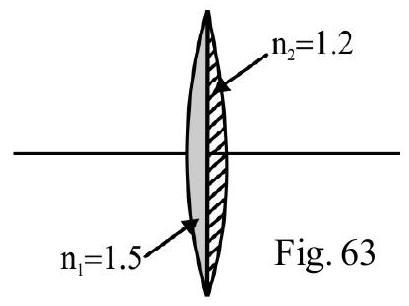
(1)
(2)
(3)
(4)
Show Answer
Correct answer: (2)
Solution:
Let and be the focal length of the two plano-convex lenses. From lens maker’s formula
and
Let fbe the focal length of the bi-convex lens i.e the combination of two plano convex lens in contact. Then
Given ? Using the thin lens formula, we get
Difficult
Lenses
59. Figure- 64 shows a thin lens for which the radii of curvature of two surfaces are equal. Also . A parallel beam of light, incident in , is bright to focus, in medium , at a distance of from the lens. The radius of curvature of the surfaces of lens is
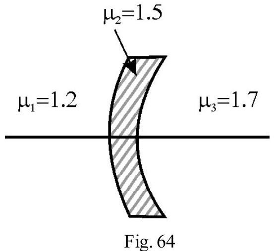
(1)
(2)
(3)
(4)
Show Answer
Correct answer: (2)
Solution:
Let be the magnitude of the radius of each surface of lens. Had there been only one surface; the incident parallel beam, after refraction would have met the principal axis at , at a distance from this surface.
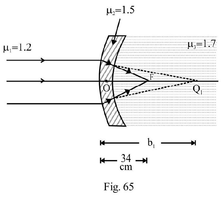
Form refraction at first surface of lens we have
For refraction at second surface, acts as a virtual object, forming the real image at . Therefore,
From refraction formula; we now get
Average
Lenses
60. Alens, having a focal length , is made of a material of dispersive power . A parallel beam of white light parallel to the principal axis, is incident on the lens. The violet and red coloured rays are brought to focus at distances and from the lens. Then
(1)
(2)
(3)
(4)
Show Answer
Correct answer: (3)
Solution:
Let and be the focal length of lens, for violet and red colour, respectively. We know [Cauchy’s relation]. From lens maker’s formula, we get
Also . From lens maker’s formula, we have
Differentiating, we get
Average
Lenses
61. A convex lens is in contact with a concave lens. The magnitude, of the ratio of their focal lengths, is . Their equivalent focal length is . The individual focal lengths (in , of the two lenses, are, respectively,
(1)
(2)
(3)
(4)
Show Answer
Correct answer: (4)
Solution:
Let and be the, respective, focal lengths of the convex and concave lens. Given
The equivalent focal length, , of combination is . Therefore,
Hence
Difficult
Lenses
62. A plano convex lens, if silvered on its plane surface, is equivalent to a concave mirror of focal length . If, however, its curved surface (only) is silvered it is equivalent to a concave mirror of focal length . The refractive index, of the material of lens, is
(1)
(2)
(3)
(4)
Show Answer
Correct answer: (2)
Solution:
Let be the radius of curvature of curved surface of plano convex lens of focal length (say), made from a material of refractive index . From lens maker’s formula, we then have
The focal length, , of the equivalent mirror, when one of the two surfaces of the lens is silvered is
Here is the focal length of the mirror formed due to silvered surface of lens. When the plane surface of the plano convex lens is silvered, and given. Therefore
When the curved surface of lens is silvered and (given). Therefore,
From equation (3) and (4), we have
From equation (3) and (5), we have
Difficult
Lenses
63. The refractive indices of material of an equi-concave lens, of radius of curvature , for wave lengths and are and , respectively. The corresponding refractive indices of an equi-concave lens, having radius of curvature, , are and . The two lens are placed co-axially in contact with each other. A parallel beam, containing light of wave lengths and is incident on the combination. It is observed that both the wave lengths are brought to focus at the same point on the principle axis. We have
(1)
(2)
(3)
(4)
Show Answer
Correct answer: (1)
Solution:
Let and be the mean values of the refractive indices of the materials of the convex and concave lenses; Let and the values of their mean focal lengths. From lens maker’s formula:
Similarly
Let and be the dispersive powers of the materials of the convex and concave lenses. Then
For the combination, the given condition is the condition for no net dispersion. It is satisfied, if
Average
Refraction
64. A convex lens is placed above an empty tank of depth . The lens forms an image of a point, on the bottom of the tank above the lens. A transparent liquid is now poured into tank upto a depth of . The distance of the image of the same point, is now above its earlier position. The refractive index, of the liquid is
(1) 1.30
(2) 1.36
(3) 1.40
(4) 1.414
Show Answer
Correct answer: (2)
Solution:
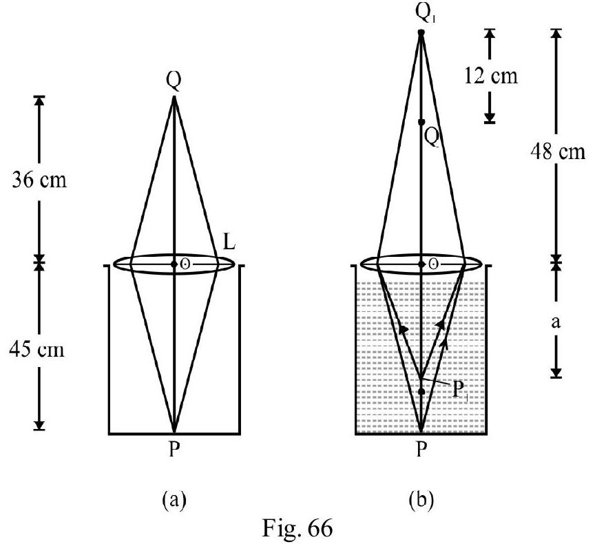
From Figure- 66 (a); ?
or
In Figure- 66 (b) liquid has been poured into the tank. Due to refraction, inside the liquid, P appears to have shifted to portion . For refraction from lens now, we have
Difficult
Lens
65. The aperture, of a given plano convex lens, is and its thickness, at the center, is . If speed of light, in the material of lens, is , the focal length of the lens, is
(1)
(2)
(3)
(4)
Show Answer
Correct answer: (4)
Solution:
Figure- 67 shows the plano convex lens . Given
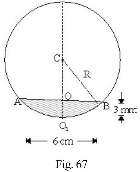
Also,
Let be the radius of curvature of the curved surface of lens. From right angled triangle , we have
The refractive index of the material of lens
The focal lenth, fof the lens is given by
Difficult
Lens
66. A tank is filled with water up to . An oil , spread on the surface of water, forms a convex surface of radius . Consider the oil as a thin lens. An object, , is placed above the surface of water. The distance of the image formed, from the
bottom of the tank, is
(1)
(2)
(3)
(4)
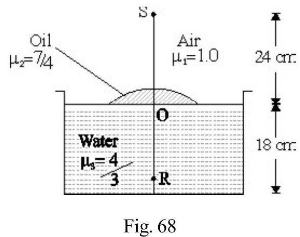
Show Answer
Correct answer: (2)
Solution:
Let fbe focal length of the oil lens. Here
refractive index of object space
refractive index of image space
refractive index of the material of nes
For the plano-convex oil-lens, we then have
Also ? Using the refraction formula,
We have
The distance of image (R) formed from the oil lens, is . Hence its distance, from the botom of the tank
Average
Lenses
67. An equiconvex lens is made of a material of refractive index . The power of lens is . A plano-concave lens is put in contact with this convex lens, co-axially, as shown in Figure- 69. If the power of combination is , the ratio, , is:
(1)
(2)
(3)
(4)

Show Answer
Correct answer: (2)
Solution:
Let (in meter) be the radius of curvature of each surface of the equi-convex lens. Then
The power, , of the plano-concave lens, is
The power, , of the combination is
Average
Lens
68. An equiconvex lens, of focal length , is made of glass . The lens is placed so that its one surface is in contact with air and its other, with a transparent medium, of refractive index 1.3. A parallel beam is incident on the lens from the air side. The emergent beam, would then meets the principle axis, at a distance from lens, where is
(1)
(2)
(3)
(4)
Show Answer
Correct answer: (2)
Solution:
Let be the radius of curvature of each surface of the lens. From lens maker’s formula, we have
Figure- 70 shows lens placed with its second surface in contact with the medium of refractive index, .
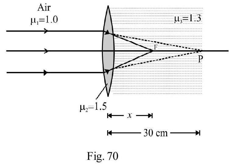
Consider the refraction at the first surface of the lens.
Here ?
Had there been only this refracting surface, the refracted raywould have meet the principal axis at P. For the second surface of the lens, acts as a virtual object; which forms the final image at . Now
Here
Difficult
Thin Lenses
69. A planoconvex lens is made of a material of refractive index . When a small object is placed away, in front of the curved surface of the lens, an image, of double its size, is produced. Due to reflection from the convex surface of the lens, another faint image is observed at a distance of from the lens. The refractive index, , and the focal length f of lens are
(1)
(2)
(3)
(4)
Show Answer
Solution:
For image, due to refraction by the convex lens, we have
Using the lens formula , we have
Let be the radius, of curvature of the curved suface of the lens. From lens-maker’s formula;
The faint image formed is due to reflection from the curved surface of the lens. We now have to use the ‘mirror formula’. Here
From equation (2) and (3), we have
Difficult
Lenses
70. A plano convex lens is placed on a plane mirror as shown in Figure- 71. For a pin, placed at a distance , there is no parallax between the pin and its image formed by the system. The space between the plane mirror, and the curved surface of lens is now filled with a transparent
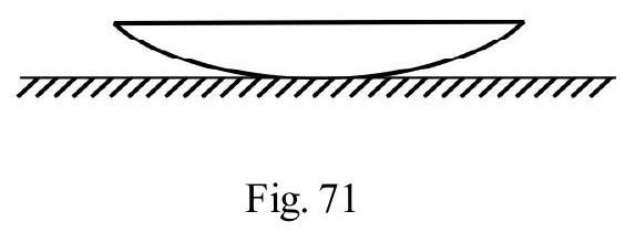
liquid, forming a liquid lens. The pin has to be raised through a distance y so that again there is no parallax between the pin and its image formed by the (new) system. The focal length of the plano-conves lens, and the liquid lens, are, respectively,
(1)
(2)
(3)
(4)
Show Answer
Correct answer: (4)
Solution:
Figure- 72 shows the ray diagram for no parallx between the image and the object pin. The rays, after refraction from the lens, must fall normally on the plane mirror so that they retrace their path. The object pin is therefore, at focus, , of the plano-convex lens. Hence
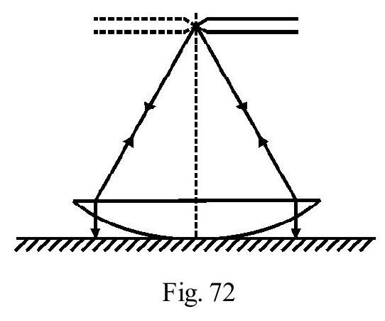
Similarly, for the combination of plano-convex lens and liquid lens, of focal length (say), the focal length of the combination, . Now
therefore
Difficult
Lenses
71. Two identical equiconvex lens and , made of a material of refractive index and having a focal length, , each, are placed in contact, co-axially, as shown in Figure- 73 (a). The space between the two lenses, is sealed at the two ends, after being filled with a transparent liquid of referactive index, , as shown in Figure- 73 (b). The change, in the equivalent focal length, of the arrangment, is
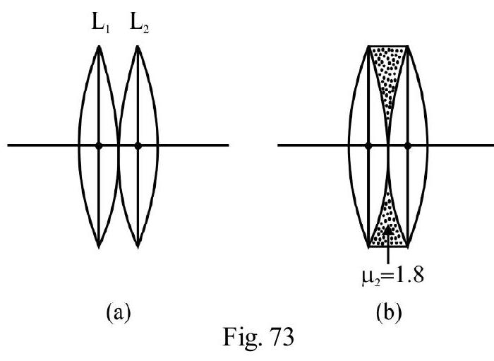
(1)
(2)
(3)
(4)
Show Answer
Correct answer: (3)
Solution:
The focal length, of each lens, in terms of the equal radii of curvature, , of its two surfaces, is
The equivalent focal length, , of the combination shown in Figure- 72 (a), is
The arrangment, shown in Figure- 72 (b), is a combination of three thin lenses. The additional lens is an equiconcave liquid lens. Let be the focal length of liquid lens. Then
The equivalent focal length, , of the arrangment shown in Figure- (b), is
The change in focal length
Difficult
Lens
72. Two thin lenses, of focal length, , and, , are made of materials of dispersive powers, and , respectively. A beam of white light, parallel to their common principal axis, is incident on the combination. If the violet and red coloured rays meet at same point on the principal axis, we must have
(1)
(2)
(3)
(4)
Show Answer
Correct answer: (4)
Solution:
The equivalent focal length, , of the combination, is
Since violet and red rays after refraction, meet at the same point on the principal axis, Differentiating aligned (1), we have
Also and . Therefore, we must have
Difficult
Lenses
73. A thin convex lens of focal length is placed co-axially at a distance, , from a concave lens of focal length . The combination assumed to behave like a thin lens, forms a real image, of same size as the object when an object is placed at a distance of from it. The distance is
(1)
(2)
(3)
(4)
Show Answer
Correct answer: (2)
Solution:
Let and be the focal lengths of the two lenses, placed co-axially, a distance apart. The combination behaves like a lens of focal length , where
Given
For the equivalent thin lens;
From equation (1) and (2), we have
Difficult
Lenses
74. A point object, , is placed at a distance of from a thin plano-convex lens of (original) focal length , whose plane surface has been silvered. The image, formed by the system, is at
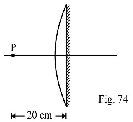
(1) to left of the system
(2) to right of the system
(3) to the left of the system
(4) to the right of the system
Show Answer
Correct answer: (3)
Solution:
Let fbe focal length of plano-convex lens, and the focal length of the mirror, formed due to silvering of the plane surface of the lens. The equivalent focal length, , of the system is given by
Given ; therefore
For the equivalent system,
or
The -ve sign indicates that the image is real, i.e. to the left of the system.
Difficult
Lenses
75.
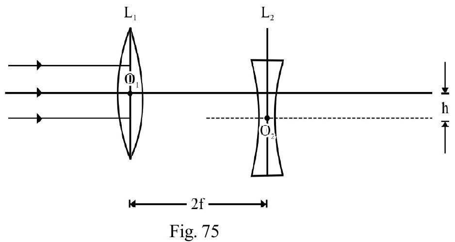
is a convex lens of focal length and is a concave lens of focal length . The two are placed a distance apart. The principle axis of two lens are parallel, but a distance apart, as shown in Figure- 75. A parallel beam is incident on . The emergent beam, after refraction at both and , is
(1) A parallel beam parallel to axis of and
(2) A parallel beam, making an angle of , in the anticlockwise direction, with the principal axis
(3) A parallel beam, making an angle of , in the clockwise direction, with the principle axis
(4) A divergent beam
Show Answer
Correct answer: (2)
Solution:
Figure- 76 shows the ray diagram. The incident parallel beam, after refraction at would have meet its principle axis at point . The point, , acts as a virtual object for the concave lens, , and is lying off the axis of , in its focal plane. The emergent beam is, therefore, a parallel beam, inclined to the principle axis of , at an angle . From right angled triangle ;
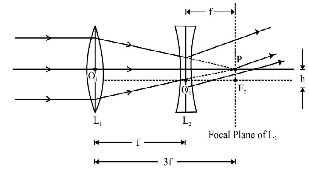
Average
Use of Lenses
76. A lens, of power , forms a virtual image of an object, (kept at a distance of ) at a distance of from it. The same lens forms a virtualimage, of another object (kept at a distance ) at a distance of from the lens.
The values of and are, respectively,
(1) and
(2) and
(3) and
(4) and
Show Answer
Correct answer: (3)
Solution:
We have here and . Hence,
or
The power, , of the lens used is ( , in meter)
We also have; for . Hence,
Solving we obtain
Hence option (3) is the correct option.
Difficult
Lenses
77. A convex lens of focal length , has a point object placed at a distance of on its principle axis, . The lens is rotated about point through an angle as shown in Fig, 77 which of the following statements is correct for the image formed by the lens in its rotated position?
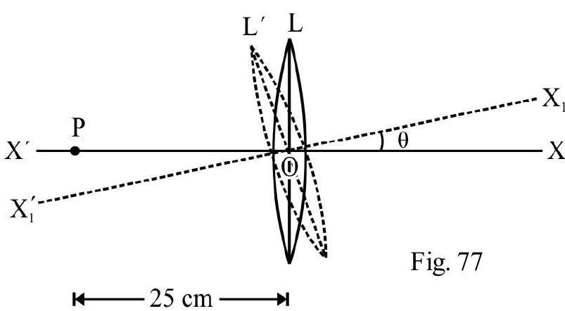
(1) Point image, at a distance on
(2) Point image, at a distance on
(3) Point image, at a distance on , at a perpendicular distance of , above
(4) Point image, at a distance below , at a perpendicular distance of
Show Answer
Correct answer: (4)
Solution:
For rotated position of lens is the principal axis. Point object, on , appears as an object of length for lens . The object distance . Given
[For small angles, ]
Also,
For the lens, in position , we have
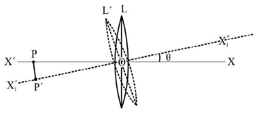
Figure- 78
Let be the magnification. Then
Negative sign, indicates image is inverted with respect to , i.e., image formed is below .
Also length ofimage
Average
Lenses
78. Which of the following spherical lens does not exhibit a net dispersion? The radii of curvature of lens surface are as given in the Figure- 78
(1)
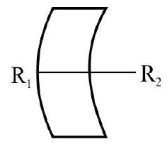
(2)
(3)
(4)
Show Answer
Correct answer: (3)
Solution:
For case (3), the radii of curvature, of the two lens surfaces, have the same magnitude and same sign. The focal length, , of this arrangement is therefore, infinity. The arrangement behaves like a parallel slab and there is no dispersion as white light passes through it.
For all the other arrangments, is finite; also the value of will be different for different colours due to variation of with . All these arrangements will therefore, cause a dispersion of the white light incident on them.
Difficult
Lenses
79. The size of the image of an object; (which is at infinity) as formed by a convex lens, of focal length , is . If a concave lens, of focal length , is placed between the convex
lens and the image, at a distance of from the convex lens, the new size of the image would be
(1)
(2)
(3)
(4)
(I.I.T 2003)
Show Answer
Correct answer: (4)
Solution:
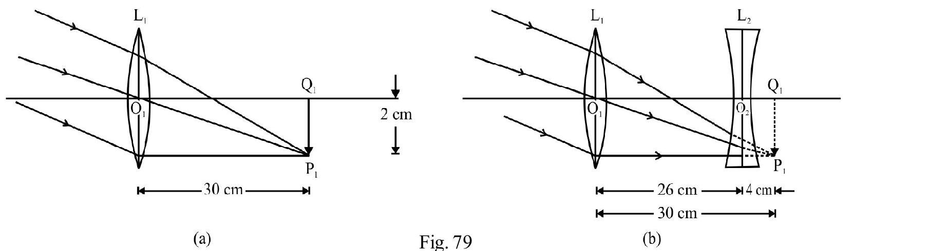
Figure- 79 (a) shows the image , being formed due to the convex lens alone. The image is formed in the focal plane of . Figure- 79 (b) shows the concave lens, , placed between and image . For the concave, , acts as a virtual object. For concave lens
From refraction formula
magnification due to concave lens
The size of final image
Easy
Telescape
80. An observer looks at a distant tree of height , with a telescope of magnifying power 20. To the observer the tree would appears.
(1) 10 times taller
(2) 10 times nearer
(3) 20 time taller
(4) 20 time nearer
Show Answer
Correct answer: (4)
Solution:
The magnitying power of a telescope, is the ratio of the angular size of image to the angular size of object. For M.P ; the angular size of image is 20 times that of object. This will be so if the image formed is 20 times nearer than the object.
Average
Huygen’s Principle
81. In Figure- 80, ab, cd and ef represent the wave-fronts of incident rays that are incident on the device XY. a’b’, c’d’, e’f’ represent the corresponding wave fronts for the rays refracted by ’ ‘. The device is a
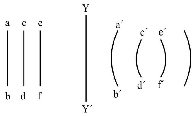
(1) convex lens
(2) concave lens
(3) plane glass-slab
(4) prism
Show Answer
Correct answer: (1)
Solution:
The incident wave fronts are plane and parallel to one another. The incident beam is, therefore, a parallel ray beam. The refracted wave fronts are spherical. The refracted beam is first a convergent beam and is then seen as divergent. This is because for XY, a convex lens, the refracted rays first converge towards the focus and then diverge away.
Average
Huygen’s Principle
82. Figure- 81 shows a plane boundary , seperating two media. is the incident wave front in medium 1 and isthe r efracted wave fr ont in medium 2. If and are the speeds of light, in medium 1 and medium 2 , respectively the ratio is
(1)
(2)
(3)
(4)
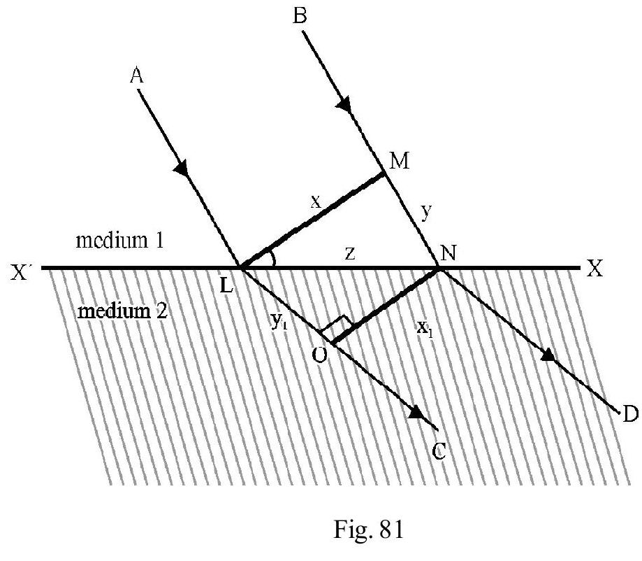
Show Answer
Correct answer: (3)
Solution:
The incident and the refracted wave fronts, , and PQ, are plane, wave front. Hence the incident rays and the refracted rays are parallel beam, as shown in the Figure- 82. Let and be the refractive indices, of medium 1 and medium 2 , respectively. From Snell’s law
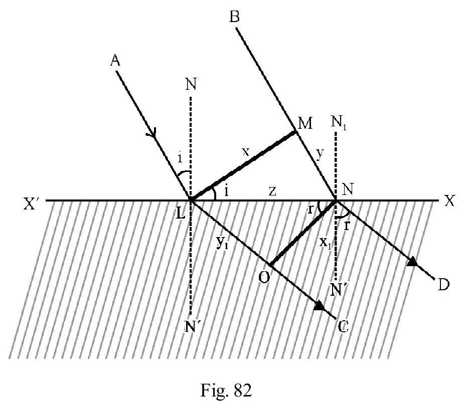
Difficult
Interference
83. In Young’s double slit experiment intensity at a point is of the maximum intensity. The angular position, of this point, is:
(1)
(2)
(3)
(4)
Show Answer
Correct answer: (3)
Solution:
In Figure- is the point where intensity ( maximum intensity). Let be the phase difference,
between the two disturbances, at P. Then
or
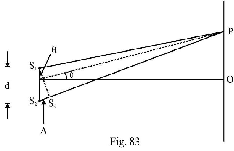
Let be the path difference between the two disturbances, at P. We know .
or
From right angled triangle ,
Difficult
Interference
84. A point source , emits light of . It is placed a small distance above a plane minor, , as shown in Figure- 84. The intensity of reflected light is of the incident light. Interference fringes are observed on a screen placed parallel to , a large distance away from it as shown in Figure- 84. The point , on the screen, corresponds to a maximum. The minimum distance, through which be moved, so that intensity at, , is again maximum, is
(1)
(2)
(3)
(4)

Show Answer
Correct answer: (2)
Solution:
Interference occurs at between the direct waves and the reflected waves. We can imagine reflected waves as coming from a virtual save , where is the image of due to reflection in the mirror. The path difference, , of the waves, at , is
Since is the position of a maximum, we have
(Note that there is a phase change of in reflected wave from ).
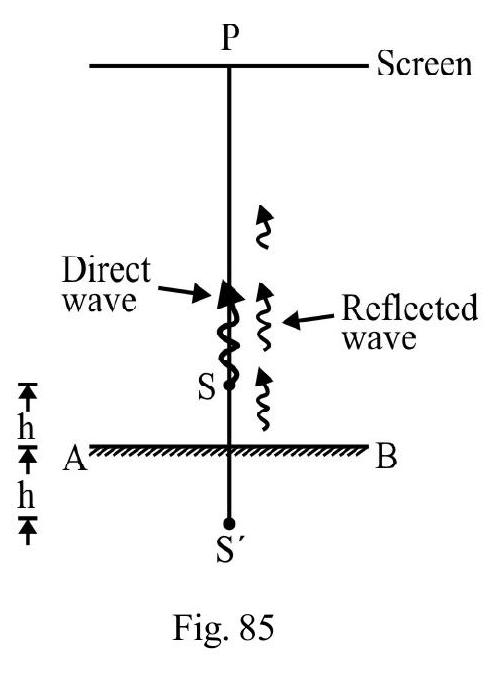
Let be minimum distance through which AB is moved, upwards or downwards, so that is again a maxima. This will so if
Difficult
Interference
85. In Young’s double slit experiment, instead of taking slits of equal width; one slit is made twice is wide as the other. Then; in the interference pattern,
(1) The intensities of both the maxima and the minima increases
(2) The intensity of the maxima increases and the minmum has zero intensity
(3) The intensity of the maxima decreases and that of the minima increases
(4) The intensity of maxima decreases and the minima has zero intensity
Show Answer
Correct answer: (1)
Solution:
When both slit have same width, intensities of and are equal, say . Then
When width of one slit, say , increases its intensity is more than . Let
Now
Hence intensities at both the maxima and the minima, become more than their earlier values.
Average
Interference
86. In the Young’s double slit experimental set up, shown in Figure- 86 here, where is wavelength of incident light. The intensity, at the maximum in the interference pattern, observed on screen, equal . The intensity, at the centeral point, , is
(1)
(2)
(3)
(4)
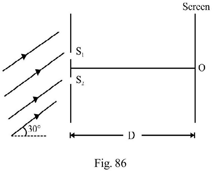
Show Answer
Correct answer: (2)
Solution:
There is an initial path difference , between and . We have
The disturbances, from and , arrive at, , with a phase difference,
Hence, the intensity, at , is
Difficult
Interference
87. In a Young’s double slit experimental set up; the wave length of incident light is . The distance between the two interferring sources The distance, of the screen, from the interferring sources, is . The minimum distance from the central fringe, of the point on the screen, where the intensity is half due to either sources, is
(1)
(2)
(3)
(4)
Show Answer
Correct answer: (3)
Solution:
Let be the intensity of each of the sources and . We know that . For the given point, we want . We also know that
where is the phase difference, between the two interferring rays, at P. Let be the distance of P from central point, . We then have
Easy
Diffraction
88. A single slit is illuminated with a parallel beam of light of wavelength . The angular width of the diffraction pattern, is measured. When the wavelength of the incident light is changed to , the width of the central maximum decreases by . The difference , is
(1)
(2)
(3)
(4)
Show Answer
Correct answer: (2)
Solution:
The angular width, of the centeral maximum, in a single slit diffraction pattern, is
Let be the angular width of the central maximum when the wavelength of incident light is . Given
Difficult
Interference
89. A coherent beam of microwaves, of wavelength , falls on a Young’s double slit arrangement. The separation, between slits, is and the screen is at a distance of . The total number of minima; observed on the screen, equals
(1) 1
(2) 2
(3) 3
(4) 4
Show Answer
Correct answer: (4)
Solution:
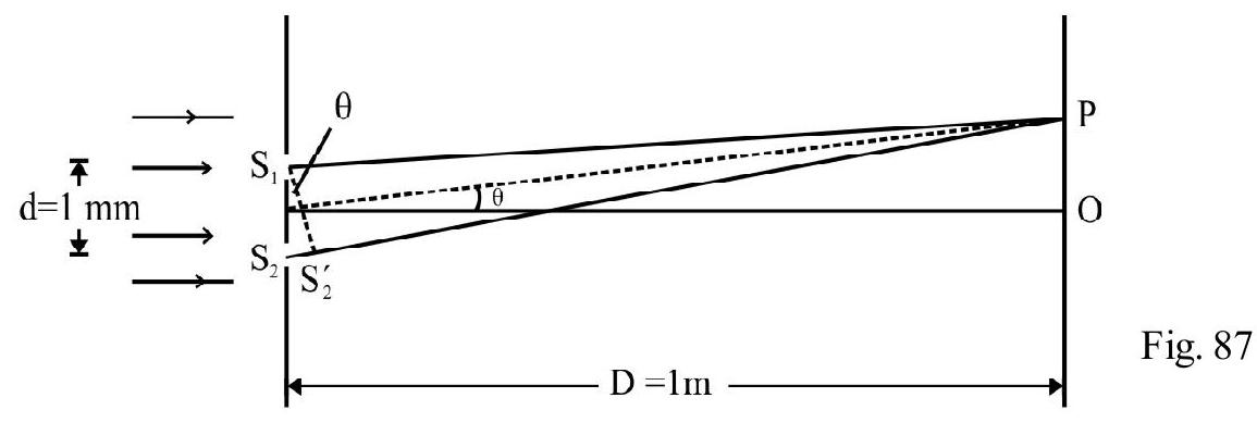
Figure- 87 shows the experiemntal set up. For any point, , on the screen, along the direction ; the path difference , between the two interferring beams, is
For minima, we have
We know that the maximum value of . Hence can be either or . Hence, there are two minima, observed above , and two below . Hence the total number of minima, observed, on the screen, is four.
Average
Interference
90. In a Young’s double slit experiment, using monochromatic light of wavelength , the path difference (in terms of integer ), corresponding to a point, having half the peak intensity, is
(1)
(2)
(3)
(4)
(I.I.T Adv. 2013)
Show Answer
Correct answer: (2)
Solution:
The intensity, I, at a point where two waves arrive with a phase difference is
where is the peak (or maximum) value of intensity. Also,
Here is the path difference, at the point considered. Given
Average
Interference
91. A monochromatic beam, of intensity , is incident on a parallel film. and are the two parallel rays produced due to reflection and refraction, at the two susfaces of the film. If the reflection and transmission coefficient are and , the ratio. , in the interference pattern, produced due to interference between and , would be
(1)
(2)
(3)
(4)
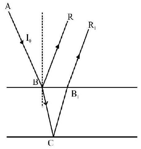
Figure- 88
Show Answer
Correct answer: (2)
Solution:
Using the definition of reflection and transmission coefficents, the intensity , of BR, and , of , are as shown in Figure- 89. Now
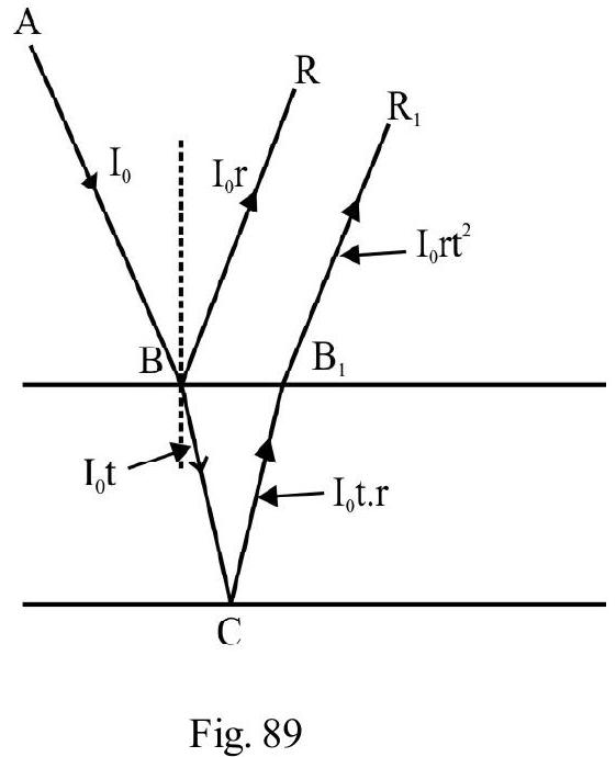
Difficult
Interference
92. In a Young’s double experiment, bi-chromatic light, having wavelengths and in it, is being used. The distance, between the plane of the slits and the screen, is . The minimum distance, between two successive regions of complete darkness, is
(1)
(2)
(3)
(4)
Show Answer
Correct answer: (3)
Solution:
Complete darkness is observed at a point where we have dark fringes due to both the wavelentghs and . Let the dark fringe, of coincide with dark fringe, of at any such point. Then, we must have
The minimum values, of and n, satisfying Equation (1) are:
The position co-ordinate, , of this point, is
The next set of values, of and , satisfying Equation (1), are
The position co-ordinate, , of this point, is
Therefore, the minimum distance, between two consecutive positions of complete darkness on the screen is
Difficult
Interference
93. A light source, which emits two wave length , is used in a Young’s double slit experiment. Let and be the fringe widths, for the wave lengths and , respectively at a point, distant, , from the central fringe. The number of fringes, observed for and , are and ; respectively. Which of the following statements is incorrect?
(1)
(2)
(3) Third maximum of , overlaps the fifth minimum of
(4) Angular seperation of fringes of , is greater than that for
Show Answer
Correct answer: (4)
Solution:
(a) The fringe width;
Since . Statement (1), is therefore, a correct statement.
(b) number of fringes of observed
number of fringes of observed
Since . Hence statement (2) is also correct statement.
(c) The distance, of maximum of , from the centeral fringe
The distance of minimum of from the centeral fringe Have statement (3) is also a correct statement.
(d) Angular width of fringe . Since , angular width of fringes of is less than for . Hence statements (4) is the (required) incorrect statement.
Difficult
Interference
94. In a Young’s double slit experiment, light of wave length is used. A thin film of refractive index, , and having a thickness is introduced in the path of light coming out of one of the slits, . Another thin film, of refractive index, and thickness , is placed in the path of light coming out of the other slit, . The intensity at the central point, then becomes of its earlier value. The relation, between and , is
(1)
(2)
(3)
(4)
Show Answer
Correct answer: (2)
Solution:
The additional path differences, and , in the path of the two interferring beams, are
Let be the phase difference, between the two interferring beams, at the central point. We have
Since , we have
From equation (1) and (2) we get
or
Difficult
Interference
95. In a Young’s double slit experiment, the seperation between the two slits is and the wave length of light used in . The intensity of light from slit 1 is four times the intensity from . Which of the following statements is correct?
(1) For , no fringe is observed on the screen
(2) For , the total number of fringes, observed on the screen, is three
(3) If intensity of light, from , is made equals to the intensity from ; the intensities of the observed dark and bright fringes, would increases
(4) If intensity of light, from , is increases so that if becomes equal to the intensity from , the intensities of the observed bright and dark fringes, would increase
Show Answer
Correct answer: (2)
Solution:
(i) For ; only the centeral maximum would be observed on screen. Hence statement (1) is incorrect.
(ii) For ; there would be three fringes observed on the screen. These are the centeral maximum, and one dark fringe (corresponding to path difference ), on either side of the central maximum. Hence statement (2) is a correct statement.
(iii) When and become equal; the intensity, at the position of dark fringes, is zero; whereas it was finite when . The intensity of dark fringes therefore, decreases ( when ), from what it was when . Hence statement (3) and (4) are both incorrect statements.
Difficult
Interference
96. In Figure- 90, CP represents a wave front and and are two rays corresponding to this wave front. The condition, for constructive interference, at , between ray and ray , is
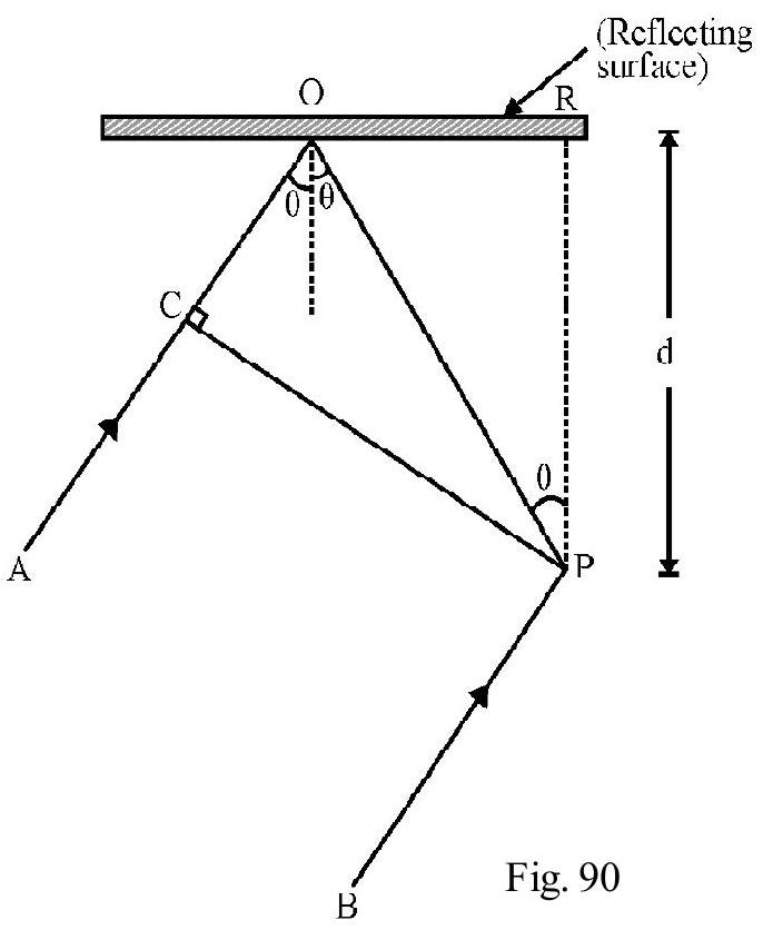
(1)
(2)
(3)
(4)
Show Answer
Correct answer: (2)
Solution:
From right angled triangle OPR,
From right angled triangle COP;
Let be the path difference, at , between the two rays. Obviously
There is an additional path difference, between the two rays due to reflection at the boundary of a denser medium. For constructive interference, at , we, therefore, have
Taking , we get
or
Difficult
Interference
97. A glass plate, of refractive index 1.5 , is coated with a thin layer of thickness and refractive index . Light, of wave length , travelling in air is incident (nearly) normally an the layer. It is partly reflected at its upper and lower ends and the two reflected rays interfere. If , the minimum value of , for which constructive interference would take place, is
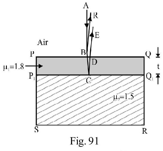
(1)
(2)
(3)
(4)
Show Answer
Correct answer: (2)
Solution:
In Figure- 91, is the glass plate and is the thin fim. is the (nearly normally) incident ray. is the reflected ray from the upper end and is the reflected ray at the lower and . DE is the corresponding emergent ray. Interference occurs between BR and DE. The path difference
There is an additional path difference of due to reflection at PQ (reflection from the boundary of a denser medium). There is no extra path difference due to reflection at , as this reflection is from the boundary of a rarer medium. For constructive interference, we therefore, have
For minimum value of . Therefore
Difficult
Interference
98. In an ideal double-slit experiment, when a glass-plate (refractive index 1.5) of thickness is introduced in the path of one of the interferring beams (wave length ), the intensity, at the position where the central fringe occured previously, remains unchanged. The minimum thickness, of the glass plate, is
(1)
(2)
(3)
(4)
(I.I.T 2002)
Show Answer
Correct answer: (1)
Solution:
The additional path difference, introduced due to the glass plate, is
Since intensity at position where central maximum occured eailer, remains same; position of one maximum must have been taken over by another maximum. This will be so if the additional path difference is an integral multiple . i.e. if
For minimum value of . Therefore,
Difficult
Interference
99. In a given set up, imagine the Young’s double slit experimental set up to be immersed completely in a liquid of . In the given set up:
distance between two slits
distance of screen from slits
wave length of light
If a thin film, of and thickness , were to be now inserted in the path of one of the two interferring sources, the position of the central fringe gets occupied by the adjacent dark fringe. The thickness, , of the film is (nearly)
(1)
(2)
(3)
(4)
Show Answer
Correct answer: (1)
Solution:
wave length of light inside liquid
The fringe width of fringes
Let be the thickness of the film introduced. The additional path difference
Since position of centeral fringe is now the position of first minimum additional path difference is
or
Average
Diffraction
100. In a single slit diffraction experimental set up, the angular width, of the central maximum, changes by when the incident wave length is changed to a new value, say, . It is also observed that while keeping , the arrangement is immersed is a transparent liquid of refractive index , the change in angular width observed now is the same as that due to a change of to its new value . The value of is
(1) 1.2
(2) 1.33
(3) 1.4
(4) 1.5
Show Answer
Correct answer: (2)
Solution:
Let and be the angular widths of central maximum for wave lengths and , respectively. Then
When the arrangement, using is immersed inside the liquid, the wave length becomes .
Since change in angular width is the same, .
Difficult
Interference
101. A thin film of thickness ; refractive index is placed inside a medium of refractive index as shown in Figure- 92. AB is a monochromatic ray of wave length incident almost normally on uper surface of film. It undergoes partial reflection as shown in Figure- 92. The condition for constructive interference between and is
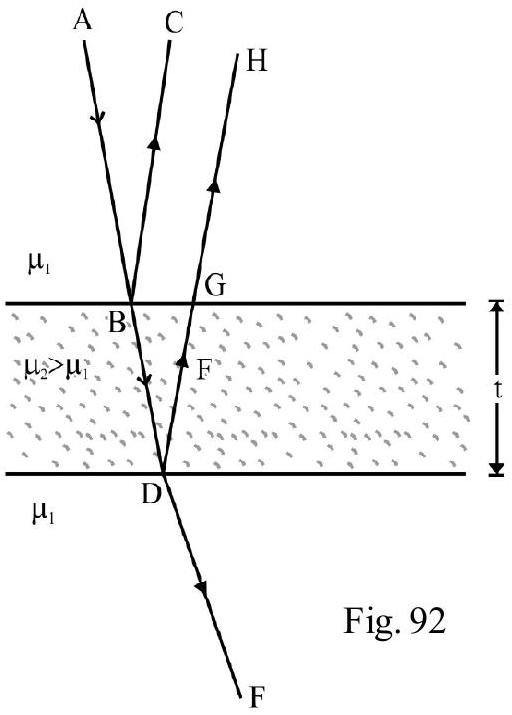
(1)
(2)
(3)
(4)
Show Answer
Correct answer: (2)
Solution:
Ray GH travels an extra distance in a medium of refractive index (for near normal incidence). This is equal to a path in medium of refractive index . Since , there is an additional path
difference of introduced due to reflection at point B. The total path difference
For constructive interference
or
or
(where . )
Average
Interference
102. In the Figure- 93, and , are two monochromatic coherent sources, both emitting light of . It is given that and , the radius of circle with centre is . Which of the following statements is incorrect?
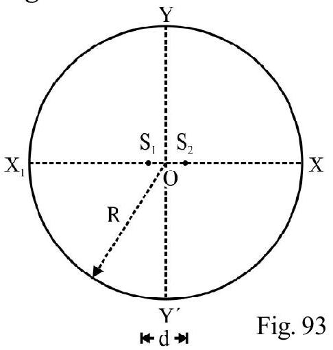
(1) and are both positions of bright fringes
(2) and are both positions of dark fringes
(3) The total number of bright fringes, observed, are 12
(4) The total number of dark fringes, observed, are 12
Show Answer
Correct answer: (2)
Solution:
At point , the two disturbances arrive having a path difference .
is an integral multiple and equals . Therefore is the position of the bright fringe.
At point ; the path difference, , between the two disturbances , is
Hence is the position of the zero order maximum. Hence and are both positions of bright fringes. Further, there are 3 bright fringes in the quddrant XY. Therefore total number of bright fringes observed equals . This would also be the total number of dark fringes observed.
Average
Diffraction
103. Using the expression
One calculates the values of by measuring , over range to . ( is known exactly). The error, in , is constant for all values of . As increaes from to ;
(1) the absolute error in, ’ ‘, remains constant
(2) the absolute error in, ’ ‘, increaes
(3) the fractional error in, ’ ‘, remains constant
(4) the fractional error in, ’ ‘, decreases
Show Answer
Correct answer: (4)
Solution:
Given
Differentiating, we get
Since there is no error is (given); . Therefore,
The absolute error in is
As increases from to decreases.
From equations (1) and (2), it follows that both the fractional error, , as well as the absolute error, , in d, decrease.
Average
Diffraction
104. The head lights of a car are apart. They emit light of . The diameter of the pupil of the observers eye is . The maximum distance of car from observer so that the two head lights are just resolved is
(1)
(2)
(3)
(4)
Show Answer
Correct answer: (4)
Solution:
The two head lights are just resolved, according to Rayleigh’s criterion; if angular width of the two lines equals half angular width of diffraction pattern at the eye of the observer. IfD is maximum distance of car from observer;
or
Average
Polarisation
105. A beam of unpolarised light, of intensity , is passed through a polariod A. It is next passed through another polariod, , which is oriented so that its principal plane makes an angle of , relative to that of . The intensity of emergent light, is
(1)
(2)
(3)
(4)
(I.I.T Main 2013)
Show Answer
Correct answer: (3)
Solution:
Since light, incident on , is unpolarised, the intensity, , of light emerging from , is
Light incident on B is plane polarised. Also the angle, between the axis of A and B is . Using Malus law; Intensity of light transmitted by B
Average
Polarisation
106. Two beams and B, of plane polarised light, (having mutually perpendicular planes of polarisation) are seen through a polariser. From the position, when beam has maximum intensity (and beam B has zero intensity), a rotation of the polaroid, through , makes the two beam appear equally bright. The initial intensities, of beam and , are and , respectively. The ratio , is
(1) 3
(2)
(3) 1
(4)
(I.I.T Mains 2014)
Show Answer
Correct answer: (4)
Solution:
When polariser is rotated by , the angle between the axis of the polariser and the analyser, for beam A, is . The intensity, , of transmitted light, is
When intensity of beam is maximum, that of beam is zero. This means that the plane of polarisation of and , are mutually perpendicular. Hence, when the axis of the polaroid makes an angle of with the plane of polarisation of A, the angle between the axis of the polared and that of beam B, is .
Therefore, ; the intensity of transmitted beam , is
Given , therefore
107.
Difficult
Reflection
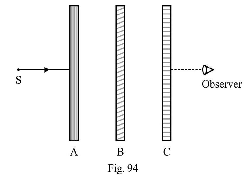
A, B and are three polariods, arranged as shown in Figure- 94. The pass axis of , is perpendicular to the pass axis of . is a monochromatic source of intensity . Polarised is rotated through one full circle. Let be the instantaneous angle between the axis of and . If is the intensity of light, as observed by observer , the graph between ’ ’ and is the graph labelled as graph
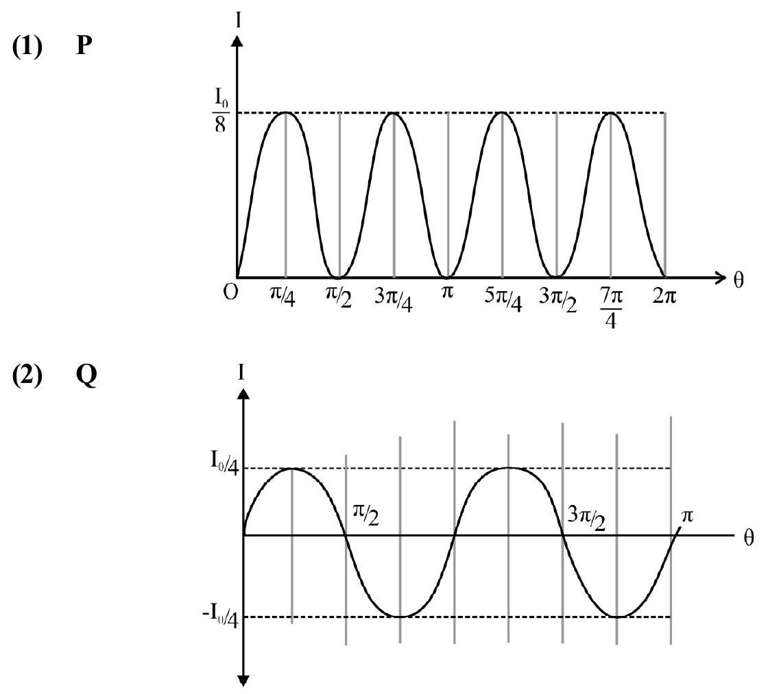
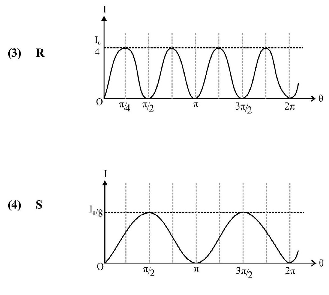
Show Answer
Correct answer: (1)
Solution:
Light, incident on polariod , is unpolarised; therefore, intensity, , of light transmitted by , is
Let be the instantaneous angle between the pass axes of A and B. Light, incident on B, is plane polarised. The intensity, , of light transmitted by , is
The instantaneous angle between the pass axes of and is . The intensity, , of light transmitted by polariod , is
It follows that I varies as and has a peak value of . These features have been correctly depicted only in the graph labelled as graph .
Average
Polarisation
108. A ray, of monochromatic light, is in incident, at an angle , on the interface between a parallel slab (of refractive index ) and another medium (of refractive index ). The emergent ray just grazes along the interface of the slab and the adjacent medium. An unpolarised ray of the same light is next incident (from air) on the other face of the slab and the reflected light gets plane polarised. The angle of incidence, of this unpolarised ray, on other face of the slab, is
(1)
(2)
(3)
(4)
Show Answer
Correct answer: (4)
Solution:
Figure- 95 shows the ray, AB, incident inside the slab on its face RS. BC is the emergent ray. Applying Snell’s law
Let be the angle of incidence, of the unpolarised light, on face PQ. Since the reflected light is now plane polarised, we get, from, Brewster’s law.
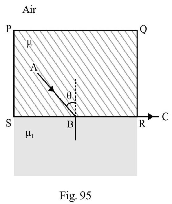
Difficult
Polarisation
109. A beam has two components, and , of plane polarised light, that are polarised in mutually perpendicular directions. Intensity of is and that of is . The composite beam passes through a polariod. If is the total intensity of light transmitted by this polariod, when its axis makes an angle with the axis of the polariser, used for beam , we wouldhave,
(1)
(2)
(3)
(4)
Show Answer
Correct answer: (4)
Solution:
Let and be the intensities, of the components and , after passing through the poloroid. From Malus law, we have
The total intensity of light transmitted by the polaroid
Average
Polarisation
110. A beam consists of an unpolarised and a plane polarised part. The beam is viewed through a polarised. On rotating the polaroid through one full circle, about the direction of propagation of the beam as axis, the intensity of the transmitted light.
(1) Remains same throughout
(2) Varies and becomes zero, twice in one full rotation
(3) Varies, between a maximum and minimum value, but the minimum value is not zero
(4) Varies, and becomes maximum, three times in one full revolution
Show Answer
Correct answer: (3)
Solution:
Since incident beam has a unpolarised part, a part, of constant intensity, passes through in all positions of the polariod. For the plane polarised component; the intensity transmitted varies between a maximum and zero. The resultant intensity, therefore, varies but does not become zero, at any stage.


