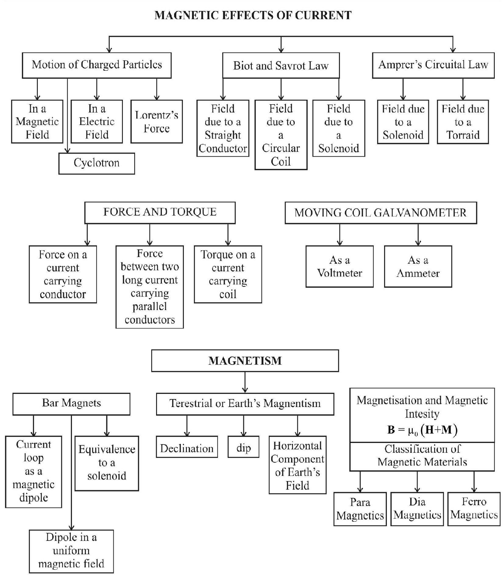
UNIT 13 MAGNETIC EFFECTS OF CURRENT AND MAGNETISM
Learning Objectives
After going through this unit you will be able to understand, appreciate and apply the following concept as:
- Basic ideas related to Biot Savart law.
- Application of Biot Savart law to a current carrying circular coil.
- Ampere’s (circulated) law.
- Applying Ampere’s law to a (i) long straight current carrying wire and (ii) solenoid.
- Force on a moving charge in uniform electric and magnetic fields - concept of Lorentz force.
- Cyclotron-its principle of working.
- Force on a current carrying conductor in a uniform magnetic field.
- Definition of the (SI) unit of current - the ampere.
- Torque expereinced by a current loop in a uniform magnetic field.
- Moving coil galvanometer - its principle and working.
- Current sensitivity of a moving coil galvanometer - factors affecting it.
- Conversion of a given moving coil galvanometer into (i) an ammeter (ii) a voltmeter.
- Equivalent magnetic dipole moment of a current carrying loop.
- Equivalence between a bar magnet and a current carrying solenoid.
- Magnetic field lines.
- Magnetic field of the earth.
- The (magnetic) elements of earth’s magnetic field.
- Classification of different materials into para, dia and ferromagnetic materials.
- Magnetic susceptibility, permeability, hysteresis.
- Differences, similarities and uses of electromagnets and permanent magnets.
Magnetic Effects of Current
$~$
In 1802, an Italian jurist Romagnosi discovered that a current carrying wire affects a nearby magnetic needle in much the same way as a magnet affects it. In 1820 Oersted made a similar observation. It was Ampere who made a significant contribution in further understanding of the magnetic effects, associated with currents. Biot and Savart then experimentally established the factors, on which the magnetic field produced by a current carrying conductor, depends.
Biot and Savart Law
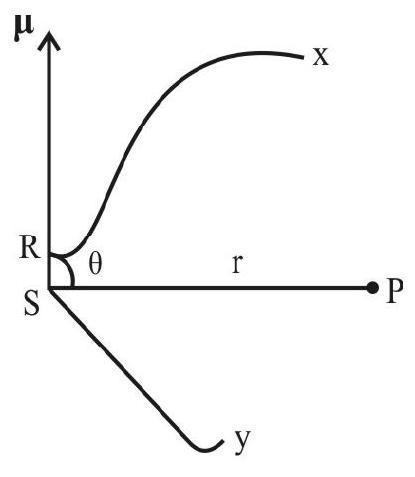
Let us consider a current carrying conductor $x y$ and let $\mathrm{P}$ be a point where the magnetic field is to be calculated. Let RS be a current element of length $\mathrm{d} \ell$. It was found that magnitude of $\mathrm{d} \mathbf{B}$, is
(i) directly proportional to current, i, through the conductor.
(ii) inversely proportional to square of distance $\mathrm{r}$, of the point $\mathrm{P}$ from the current element and (iii) directly proportional to $\mathrm{d} \ell \sin \theta$ where $\theta$ is the angle bewteen the current element $\mathrm{d} \ell$ and the radius vector $\mathbf{r}$.
Combning these we get
$~$
$$ \begin{aligned} |\mathrm{d} \mathbf{B}| & \propto \frac{\mathrm{id} \ell \sin \theta}{\mathrm{r}^{2}} \\ \text { or } \quad|\mathrm{d} \mathbf{B}| & =\mathrm{K} \frac{\mathrm{id} \ell \sin \theta}{\mathrm{r}^{2}} \end{aligned} $$
where $\mathrm{K}$ is a constant of proportionality
The constant $\mathrm{K}$ is analogus to constant of proportionality appearing in Coulomb’s law. It depends upon the system of units. In SI units K is choosen, experimentally, (keeping in mind that the unit of the current is the ‘ampere’) to have the value.
$$ \mathrm{K}=\frac{\mu _{0}}{4 \pi} $$
Here $\mu _{0}$ is a constanst, called the PERMEABILITY of free space, and its value is
$$ 4 \times 10^{-7} \frac{\text { weber }}{\text { ampere meter }} $$
Hence $|\mathrm{d} \mathbf{B}|=\frac{\mu _{0}}{4 \pi} \frac{\mathrm{id} \ell \sin \theta}{\mathrm{r}^{2}}$
To incorporate the direction, we have to write
$$ |\mathrm{d} \mathbf{B}|=\frac{\mu _{0}}{4 \pi}\left(\frac{\mathrm{i} \mathbf{d} \ell \times \hat{\mathrm{r}}}{\mathrm{r}^{2}}\right) $$
$~$
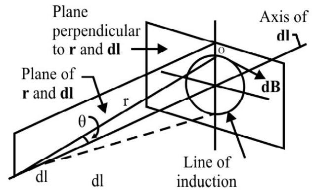
Thus $\mathrm{d} \mathbf{B}$ is always perpendicular to the plane formed by $\mathbf{r}$ and $\mathbf{d} \boldsymbol{\ell}$ as shown. This can be further understood by imagining a right hand screw to be placed at $\mathrm{P}$ such that it is normal to the plane formed by $\mathbf{d} \boldsymbol{\ell}$ and $\mathbf{r}$. Rotate the screw in the dirction that makes $\boldsymbol{d} \boldsymbol{\ell}$ coincide with $\mathbf{r}$. The direction of advancement of this screw than gives the direction of $\mathrm{dB}$.
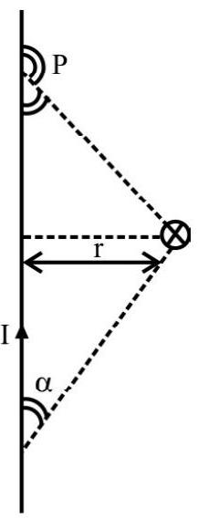
Using Biot and Savart law, we can form a general procedure for carrying out mathematical calculations. We can show that for straight wire, carrying a current $\mathrm{i}$,
$$ |\mathbf{B}|=\frac{\mu _{0} \dot{\mathrm{i}}}{4 \pi \mathrm{r}}[\cos \alpha+\cos \gamma] $$
 $~$
$~$
For an infinitely long straight wire, we have, in this limiting case, both $\alpha$ and $\gamma$ tending to zero. Thus, for an infinite straight wire,
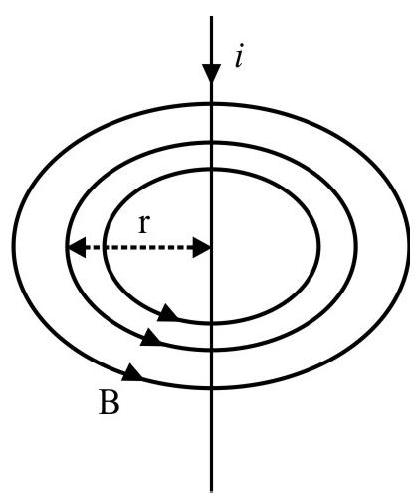
$$ |\mathbf{B}|=\frac{\mu _{0} \mathrm{i}}{2 \pi \mathrm{r}} $$
$~$
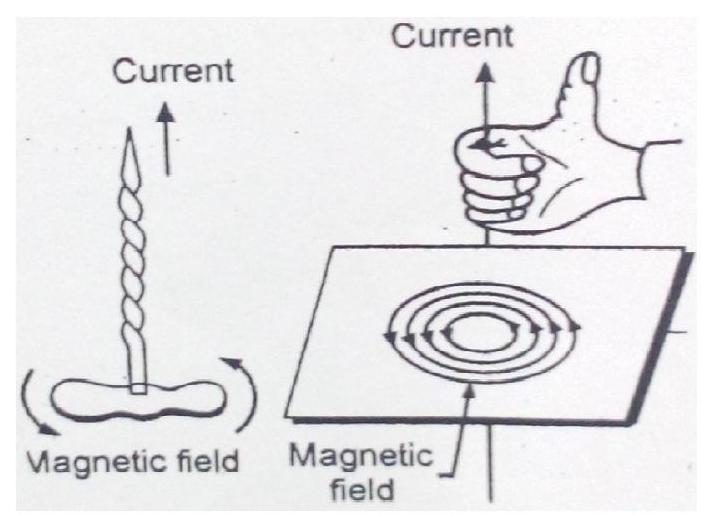
The pattern of field lines of this magnetic field is shown in figure. We have the so called right hand thumb rule to find the direction of this field.
According to this rule - “If we grasp the straight conductor in the palm of our right hand so that the thumb points in the direction of flow of current, the sense in which fingers curl, gives the direction of the magnetic field lines”.
Example-1 :
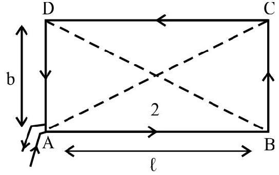
Show that the magnetic field at the centre of a rectangular coil, of sides $\ell$ and $\mathbf{b}$, carrying a current $\mathbf{I}$, is given by
$$ |\mathbf{B}|=\frac{2 \mu _{0} \mathrm{I} \sqrt{\ell^{2}+\mathrm{b}^{2}}}{(\pi \ell \mathrm{b})} $$
$~$
Show Answer
Solution:
Denoting by $\ell _{1}$ and $\ell _{2}$ the distances of two ends of the wire, from the foot of the perpendicular, drawn from the field point, on a wire of finite length, we can write.
$$ |\mathbf{B}|=\frac{\mu _{0} \mathrm{I}}{4 \pi \mathrm{a}}\left[\frac{\ell _{1}}{\sqrt{\ell _{1}^{2}+\mathrm{a}^{2}}}+\frac{\ell _{2}}{\sqrt{\ell _{2}^{2}+\mathrm{a}^{2}}}\right] $$
Now the direction of field due to all the wires, $\mathrm{AB} \& \mathrm{BC}, \mathrm{CD}$ and $\mathrm{DA}$ are the same; perpendicular to the plane of the rectangle and directed outward.
The field at $\mathrm{O}$, due to the wires $\mathrm{AB}$ and $\mathrm{CD}$ are equal and is given by
$$ \left|\mathbf{B} _{1}\right|=\frac{\mu _{0} \mathrm{I}}{4 \pi \frac{\mathrm{b}}{2}}\left[\frac{\frac{\ell}{2}}{\sqrt{\left(\frac{\ell^{2}}{2}\right)^{2}+\left(\mathrm{b}^{2} / 2\right)^{2}}}+\frac{\frac{\ell}{2}}{\sqrt{\left(\frac{\ell^{2}}{2}\right)^{2}+\left(\mathrm{b}^{2} / 2\right)^{2}}}\right] $$
Similarly the fields, due to wires $\mathrm{BC}$ and $\mathrm{DA}$, at $\mathrm{O}$, are equal and is given by
$$ \left|\mathbf{B} _{2}\right|=\frac{\mu _{0} \mathrm{I}}{4 \pi\left(\frac{\ell}{2}\right)}\left[\frac{\frac{\mathrm{b}}{2}}{(\mathrm{~b} / 2)^{2}+(\ell / 2)^{2}}+\frac{\frac{\mathrm{b}}{2}}{\left(\frac{\mathrm{b}}{2}\right)^{2}+\left(\frac{\ell}{2}\right)^{2}}\right] $$
Hence the net magnetic field, at $\mathrm{O}$, is
$$ |\mathbf{B}|=2\left|\mathbf{B} _{1}\right|+2\left|\mathbf{B} _{2}\right| $$
Substituting the values and simplifying we get
$$ |\mathbf{B}|=\frac{2 \mu _{0} \mathrm{I} \sqrt{\ell^{2}+\mathrm{b}^{2}}}{(\pi \mathrm{b} \ell)} $$
Field due to a Circular Coil (i) at a Point on the Axis of the Coil and (ii) at the Centre of the Circular Coil
To calculated the field due to a circular coil at point $\mathrm{P}$ on it axis (see figure) we take a element $\mathrm{AB}$ of the circular coil. The field due to this element is

$~$
$\mathrm{dB}=\frac{\mu _{0}}{4 \pi} \frac{\mathrm{id} \ell}{\mathrm{r}^{2}}$
$\left(\theta=90^{\circ}\right)$

$~$
We resolve this field into perpendicular component $(\mathrm{dB} \cos \beta)$ and parallel component $(\mathrm{dB} \sin \beta)$. Now if we take a symmetrically situated element $A^{\prime} B$ ’ on the opposite end of the diameter and similarly resolve into parallel and perpendicular components and add the field component’s due to these two elements we find that the perpendicular components cancels out. Whatever is true for one pair of elements is also trace for every other pair. Hence we conclude that the field due to a circular coil at a point other on its axis is along the axis of the coil and is given by
$$ \mathrm{B}=\left[\frac{\mu _{0} \mathrm{i}}{4 \pi}\right] \frac{\mathrm{d} \ell}{\mathrm{r}^{2}} \sin \beta $$
Now $\sin \beta=\frac{\mathrm{a}}{\mathrm{r}}$ and $\mathrm{r}^{2}=\mathrm{a}^{2}+x^{2}$

$~$
Putting these values we obtain, after integration.
$$ |\mathbf{B}|=\frac{\mu _{0}}{2} \frac{\mathrm{ia}^{2}}{\left(\mathrm{a}^{2}+x^{2}\right)^{3 / 2}} $$
At the centre of the coil, $x=0$ and we have
$$ B=\frac{\mu _{0} i}{2 a} $$
There is a simple rule for finding the polarity of the two faces of a current carrying circular coil. According to the rule when an observer looking at the circular coil, finds the current to be flowing in the anticlockwise sense that face of the coil behaves like the $\mathrm{N}$-pole of the equivalent magnet. On the other hand, if the current is seem to flow in the clockwise sense that face of the coil behaves like the $\mathrm{S}$-pole of the equivalent magnet.

$~$
‘Far Off’ Field of a Circular Coil
In the expression
$$ |\mathbf{B}|=\frac{\mu _{0} \mathrm{ia}^{2}}{2\left(\mathrm{a}^{2}+x^{2}\right)^{3 / 2}} $$
if we have $x > > \mathrm{a}^{2}$ than the field due to a circular coil, at a far off point on its axis, becomes equal to
$$ |\mathbf{B}| \simeq \frac{\mu _{0} \mathrm{ia}^{2}}{2 x^{3}}=\frac{\mu _{0} \mathrm{Ai}}{2 \pi x^{3}} \quad\left(\mathrm{~A}=\pi x^{2}\right) $$
We will discuss later that a current carrying circular loop is equivalent to a magnetic dipole with dipole magnetic moment $|\mathbf{m}|$ equal to (iA) where $A$ is the area a of the loop and $i$ the current flowing in the loop. Hence we can will be
$$ |\mathbf{B}| \simeq \frac{\mu _{0} \mathrm{~m}}{2 \pi x^{3}} $$
which can be shown to be the field due to a (small) magnetic dipole at a far off point.
Hence a current carrying circular loop behaves like a magnetic dipole with magnetic moment.
$$ |\mathbf{m}|=\mathrm{iA} $$
Example-2 :
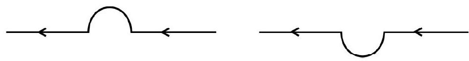
A straight wire, carrying a current of $12 \mathrm{~A}$ is bent into a semicircular arc of radius $2 \mathrm{~cm}$, as shown. What is the direction and magnitude of $B$ at the centre of the arc? What will happen if the wires were bent into a semicircular are of the same radius but in the opposite sense as shown?
$~$
Show Answer
Solution:
The magnetic field at the centre of a circular coil of radius $r$ is given by
$$ B=\frac{\mu _{0} \mathrm{i}}{2 \mathrm{r}} $$
Hence the magnetic field, at the centre of a semicircular arc, of radius, $r$, would be given by
$$ |\mathbf{B}|=\frac{1}{2}\left(\frac{\mu _{0} \mathrm{i}}{2 \mathrm{r}}\right)=\frac{\mu _{0} \mathrm{i}}{4 \mathrm{r}} $$
Hence $B=\frac{4 \pi \times 10^{-7} \times 12}{4 \times 0.02} \mathrm{~T}=1.9 \times 10^{-4} \mathrm{~T}$
The field, would be normal to the plane of paper, going into it.
In the second case, the field would be normal to the plane of paper but going out of it.
Example-3 :
If the field, normal to the plane of a wire of $n$ turns and radius $r$, carrying a current $i$, is measured on the axis of coil, at a small distance $h$, from the centre of the coil, show that it is smaller than the field at the centre, by the fraction $\frac{3 \mathrm{~h}^{2}}{2 \mathrm{r}^{2}}$.
Show Answer
Solution:
The magnetic field $\mathrm{B}$, at a point on the axis distant $\mathrm{h}$ from the centre, is given by
$$ \mathrm{B}=\frac{\mu _{0} \mathrm{Nir}^{2}}{2\left(\mathrm{r}^{2}+\mathrm{h}^{2}\right)^{3 / 2}} $$
The field $\mathrm{B} _{\mathrm{C}}$ at the centre of the coil is $\mathrm{B} _{\mathrm{C}}=\frac{\mu _{0} \mathrm{Ni}}{2 \mathrm{r}}$
$\therefore \quad B _{C}-B=\frac{\mu _{0} N i}{2 r}-\mu _{0} N i \frac{r^{2}}{\left(r^{2}+h^{2}\right)^{3 / 2}}$
or
$$ \begin{aligned} & \therefore \quad B _{C}-B=\frac{\mu _{0} N i}{2}\left[\frac{1}{r}-\frac{r^{2}}{r^{3}\left(1+\frac{h^{2}}{r^{2}}\right)^{-3 / 2}}\right] \\ & =\frac{\mu _{0} N i}{2}\left[\frac{1}{r}-\frac{1}{r}\left(1+\frac{h^{2}}{r^{2}}\right)^{-3 / 2}\right] \\ & =\frac{\mu _{0} N i}{2}\left[\frac{1}{r}-\frac{1}{r}\left(1-\frac{3}{2} \frac{h^{2}}{r^{2}}+\ldots \ldots\right)\right]=\frac{\mu _{0} N i}{2}\left(\frac{3 h^{2}}{2 r^{3}}\right) \end{aligned} $$
The fractional decrease in the field is given by
$$ \frac{\left(B _{C}-B\right)}{B _{C}}=\frac{\left(\frac{\mu _{0} i}{2}\right)\left(\frac{3 h^{2}}{2 r^{3}}\right)}{\left(\frac{\mu _{0} N i}{2 r}\right)}=\frac{3}{2}\left(\frac{h^{2}}{r^{2}}\right) $$
Example-4 :
A straight wire, of length $\left(\frac{\pi}{2}\right) \mathrm{m}$, is bent into a circular shape. If the wire were to carry a current of $5 \mathrm{~A}$, calculate the magnetic field due to it, before bending, at a point distance 0.01 times the radius of the circle formed from it. Also calculate the magnetic field at the centre of the circular loop formed for the same value of current.
Show Answer
Solution:
The radius, $\mathrm{r}$, of the circular coil, is given by $2 \pi \mathrm{r}=\frac{\pi}{2} \quad \therefore \quad \mathrm{r}=\frac{1}{4} \mathrm{~m}=0.25 \mathrm{~m}$
When the wire is straight, the distance of the field point is $\mathrm{r}^{\prime}=0.01 \mathrm{r}=(0.01 \times 0.25) \mathrm{m}$
It is obvious that this distance is very small as compared to the length of the wire. ( $\therefore$ wire can be taken of infinite length).
$\therefore$ Magnetic field due to the straight wire is
$$ \mathrm{B}=\frac{\mu _{0} \mathrm{i}}{2 \pi \mathrm{r}}=\frac{2 \times 10^{-7} \times 5}{0.01 \times 0.25} \mathrm{~T}=4 \times 10^{-7} \mathrm{~T} $$
The magnetic field, at the centre of the circle, carrying a current of $5 \mathrm{~A}$, is given by
$$ \begin{aligned} & \mathrm{B} _{\text {loop }}=\frac{\mu _{0} \mathrm{i}}{2 \mathrm{r}}=\frac{10^{-7} \times 5}{2 \times 0.25} \mathrm{~T} \\ & \simeq 1.25 \times 10^{-5} \mathrm{~T} \end{aligned} $$
Example-5 :
In the Bohr model of the hydrogen atom the electron circulaters around nucleus in an orbit of radius $5.1 \times 10^{-11} \mathrm{~m}$ at a frequency of $6.8 \times 10^{15} \mathrm{~Hz}$. Find the value of $B$ set up at the centre of the orbit.
Show Answer
Solution:
Since $i=\frac{\text { charge }}{\text { time }}$ and time period $=\frac{1}{\text { frequency }}$
We have, $\mathrm{i}=\mathrm{e \upsilon}$
$\therefore \quad \mathrm{i}=\left(1.6 \times 10^{-19} \times 6.8 \times 10^{15}\right) \mathrm{A}=1.1 \times 10^{-3} \mathrm{~A}$
Hence the magnetic field, at the centre of the circular orbit, is
$$ \mathrm{B}=\frac{\mu _{0} \mathrm{i}}{2 \mathrm{r}}=\frac{4 \pi \times 10^{-7} \times 1.1 \times 10^{-3}}{2 \times 5.1 \times 10^{-11}} \mathrm{~T} \simeq 13.55 \mathrm{~T} $$
(It is quite a large magnetic field indeed!)
Field due to a Solenoid
A solenoid consists of a large number of turns of (insulated) wire wound very closely on an appropriate cylindrical core. Let us calculate the field due to a solenoid at a point $\mathrm{P}$ on its axis. Let the solenoid be wound with $\mathrm{N}$ turns of wire and let $\mathrm{a}$ and $\mathrm{L}$ be its radius and length. We than have $\mathrm{n}=\frac{\mathrm{N}}{\mathrm{L}}$, where $\mathrm{n}$ is the number of turns per unit length.

$~$
Let $\mathrm{P}$ be any point on the axis of the solenoid
The magnetic field at this point due to any one turn of the solenoid whose centre is at a distance $z$ from this point is
$$ \mathbf{d B}^{\prime}=\frac{\mu _{0} ~ \mathrm{i}^{2}}{2\left(\mathrm{a}^{2}+\mathrm{z}^{2}\right)^{3 / 2}} $$
If we consider a length dz of the solenoid around this turn, this length would contain ndz circular coils each of which can be very nearly regarded as having its centre at the same distance $z$ from the point $P$. Hence the total magnetic field at $\mathrm{P}$ due to this length dz of the solenoid is given by
$$ \mathrm{d} \mathbf{B}=(\mathrm{ndz}) \mathbf{d B ^ { \prime }}=\frac{\mu _{0} ~ \mathrm{i ~ n ~ a}^{2}}{2\left(\mathrm{a}^{2}+\mathrm{z}^{2}\right)^{3 / 2}} \mathrm{dz} $$
Hence $|\mathbf{B}|$, the field due to solenoid can be written as
$$ |\mathbf{B}|=\frac{\mu _{0} ~ \mathrm{i ~ n ~ a}^{2}}{2} \int _{\mathrm{z}=\ell _{2}}^{\mathrm{z}=\ell _{1}} \frac{\mathrm{dz}}{\left(\mathrm{a}^{2}+\mathrm{z}^{2}\right)^{3 / 2}} $$
where $\ell _{1}$ and $\ell _{2}$ are the distance of the two ends of the solenoid from $\mathrm{P}$.
We put $\mathrm{z}=\mathrm{a} \cos \theta$
On integrations, we get
$$ \mathbf{B}=\frac{\mu _{0} ~ \mathrm{i ~ n ~ a}^{2}}{2} \frac{1}{\mathrm{a}^{2}}(\cos \beta-\cos \alpha) $$
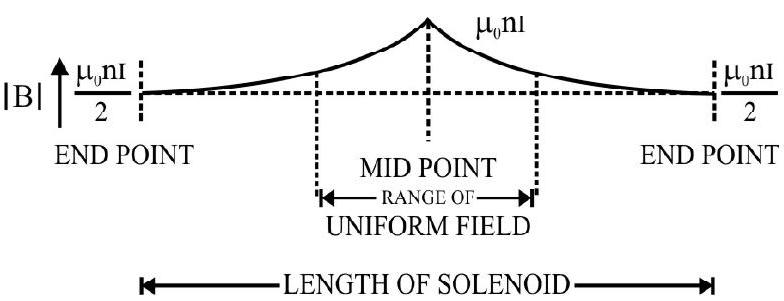
For an infinte solenoid we then have $\mathbf{B}=\left|\mu _{0} \mathrm{i}(\mathrm{N} / \mathrm{L})\right|=\mu _{0}$ in
$|\mathbf{B}|$ (at the end points), is $\frac{\mu _{0} \text { in }}{2}$
The axial field of a long solenoid thus varies as shown in the figure. We can thus conclude the axial field of a long solenoid is very nearly uniform over a small range around its midpoint.
$~$
We show below the field lines of this magnetic field. This pattern is very similar to the magnetic field lines of magnetic field of a bar magnet. Hence a solenoid is often viewed as the equivalent of a bar magnet.

$~$
Ampere’s Circuital Law
According to this law, the line intergral of the magnetic field, around a closed curve, is equal to $\mu _{0} i$ where is the current enclosed by the path of integration.
Thus,
$$ \oint \mathbf{B} \cdot \mathrm{d} \ell=\mu _{0} \mathrm{i} $$
Since $\oint \mathbf{B} . \mathrm{d} \ell$ is not equal to zero, it is important to realize that the magnetic field is not a Conservative Field.
We can easily check the validity of Ampere’s Circuital Law. We have seen that the magnetic field due to a long straight wire is given by
$$ B=\frac{\mu _{0} i}{2 \pi r} $$
$~$
This field has its field lines as shown in the figure. Let us calculate the line integral of this field around any circle of radius $\mathrm{r}$.
Along the circle considered, all the linear line elements $\mathrm{d} \ell$ are directed along $\mathbf{B}$, so that we can write
$\mathbf{B} . \mathbf{d} \ell=\mathbf{B d} \ell$
Hence $\oint \mathbf{B} \cdot \mathrm{d} \ell=\oint \mathbf{B} \cdot \mathrm{d} \ell=\mathbf{B} \oint \mathrm{d} \ell$
$ \therefore \quad \oint \mathbf{B} \cdot \mathrm{d} \ell=\left(\frac{\mu _{0} \mathrm{i}}{2 \pi \mathrm{r}}\right) \times(2 \pi \mathrm{r})=\mu _{0} \mathrm{i} $
Thus $\oint \mathbf{B} \cdot \mathbf{d} \ell=\mu _{0} \mathrm{i}$, as per Ampere’s circuital law.
Applications of Ampere’s Circuital Law
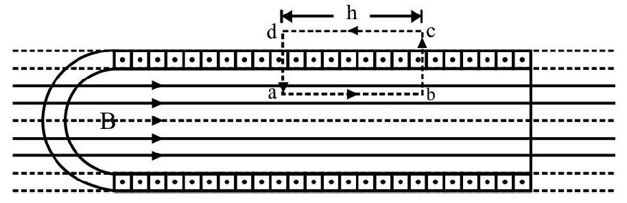
(i) We apply Ampere’s law to calculate the field due to long solenoid. For a long solenoid the field is uniform near the centre and parallel to axis of the solenoid. We calculate its line integral around the path abcd, as shown.
We can write,
$$ \oint \mathbf{B} . \mathbf{d} \ell=\int _{\mathrm{a}}^{\mathrm{b}} \mathrm{B} . \mathrm{d} \ell+\int _{\mathrm{b}}^{\mathrm{c}} \mathrm{B} . \mathrm{d} \ell+\int _{\mathrm{c}}^{\mathrm{d}} \mathrm{B} . \mathbf{d} \ell+\int _{\mathrm{d}}^{\mathrm{a}} \mathrm{B} . \mathrm{d} \ell $$
$~$
The second and fourth integrals are zero each because at every point of these paths $\theta=90^{\circ}$.
The integral $\int _{\mathrm{a}}^{\mathrm{b}} \mathbf{B} . \mathrm{d} \ell=\mathrm{Bh} \quad \quad \quad(\because$ B.d $\ell=\mathrm{Bd} \ell)$
Also for chosen path, the side cd can be taken very far off from the solenoid, so that B at every point, along it zero. Hence $\int _{\mathrm{c}}^{\mathrm{d}} \mathbf{B} \cdot \mathbf{d} \ell=0$
Hence $\oint \mathbf{B} \cdot \mathbf{d} \ell=\mathrm{Bh}=\mu _{0} \mathrm{i} _{\text {enclosed }}$
Now $\mathrm{i} _{\text {enclosed }}=\mu _{0} \mathrm{i}\left(\frac{\mathrm{N}}{\mathrm{L}}\right) \mathrm{h} \quad\quad\quad(\mathrm{i}=$ current through each turn $)$
$\therefore \quad \mathrm{B}=\mu _{0} \mathrm{i}\left(\frac{\mathrm{N}}{\mathrm{L}}\right)=\mu _{0} \mathrm{in}$
where $n\left(=\frac{N}{L}\right)$ is the number of turns per unit length of the solenoid.
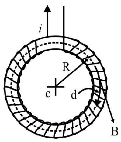
(ii) Magnetic Field of A toroidal Solenoid
A toroidal solenoid can be thought of a straight solenoid bent into the shape of a circle so that its ends join together. A toroidal winding is shown in the figure.
To calculate $|\mathbf{B}|$ at a point $\mathrm{P}$, we consider a closed path of integration shown by the dotted lines; a circle of radius $r$. From symeetrary $|\mathbf{B}|$ will have the same magnitude at every point along the path of integration. We have seen that, the magnetic field due to a long straight solenoid, is along its axis. Since there are no ends of a toroidal solenoid the same conditions apply. Also the axis of the solenoid has become a circle. Hence
$~$
$$ \oint \mathbf{B} \cdot \mathrm{d} \ell=\mathrm{B} \oint \mathbf{d} \ell=2 \pi \mathrm{rB} $$
$$ \begin{aligned} & \therefore \quad \oint \mathbf{B} \cdot \mathbf{d} \ell=2 \pi \mathrm{rB}=\mu _{0} \mathrm{I} \\ & \therefore \quad B=\frac{\mu _{0} \mathrm{I}}{2 \pi \mathrm{r}} \end{aligned} $$
Now the considered path of integration, passes through, all the $\mathrm{N}$ turns of solenoid, each carry a current i, therefore $\mathrm{I}=\mathrm{N}$ i
$$ \mathrm{B}=\left(\frac{\mu _{0} \mathrm{iN}}{2 \pi \mathrm{r}}\right) $$
Example-6 :
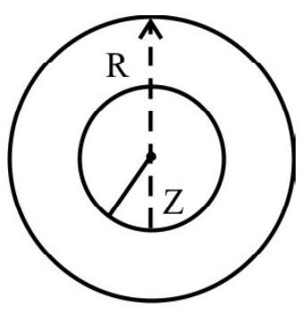
A long straight solid cylinderical wire, of radius $R$, carries a current $i$ uniformly distributed all over its circular cross section. FInd the magnetic field at a distance $\mathrm{z}$ from the axis of wire.
Show Answer
Solution:
A section of solid metal wire of radius $\mathrm{R}$ prependicular to its length is represented in the figure.
$~$
Let us consider a point $\mathrm{P}$, lying inside the wire at a perpendicular distance $\mathrm{r}$, from the axis of wire. To apply Ampere’s Circuital law, we considers a circular path of radius $\mathrm{z}$ around the axis of wire. Over this path, because of symmetry consideractions, the magnetic field produced due to the current in the wire, will be equal at all points on the circular path and will have a tangential direction.
By Ampere’s circuital law, we then have
$$ \oint \mathbf{B} \cdot \mathbf{d} \ell=\mu\left(\frac{\mathrm{iz}^{2}}{\mathrm{R}^{2}}\right)(\text { for } \mathrm{z}<\mathrm{R}) $$
$\because$ Current inclosed by the circular path is $\frac{\mathrm{i}}{\pi \mathrm{R}^{2}} \times \pi \mathrm{z}^{2}=\frac{\mathrm{i} \mathrm{z}^{2}}{\mathrm{R}^{2}}$
$\therefore \quad \mathrm{B} 2 \pi \mathrm{z}=\frac{\mu \mathrm{iz}^{2}}{\mathrm{Rz}}$
However, the current enclosed by the circular path would be $\mathrm{i}$ when $\mathrm{P}$ lies outside the wire.
Hence we have, for $\mathrm{z}>\mathrm{R}$,
B $2 \pi z=\mu _{0} \mathrm{i}$
$$ B=\frac{\mu _{0} \mathrm{i}}{2 \pi z} $$
Motion of Changed Particles in Magnetic and Electrid Fields
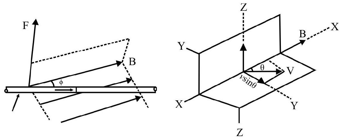
Let us consider a region in space where the magnetic field is uniform and is along $\mathrm{x}$-axis. Let a positive change $q$ move along the $y$ axis with a consted speed $v$. Experiments show that the changed particle does not experience any force when it is moving parallel to the direction of the magnetic field. Also it is observed that (in other cases) the charged particle experiences a force in a direction perpendicular to both $\mathbf{v}$ and $\mathbf{B}$, the magnitude of the force experienced by charged particle when it is moving perpendicular to $\mathbf{B}$, is given by $|\mathbf{F}|=$ qvB
$~$
$~$
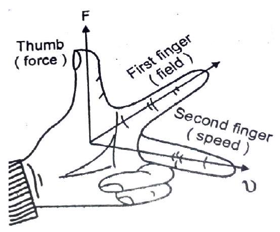
For a positive charge the direction of the force according to Fleming left hand rule, is explained in the adjoining figure.
For a negatively charged particle the direction of force is opposite to that of a positive charge.
However when the charged particle is moving with its velocity v, making an angle $\theta$ with the direction of $\mathbf{B}$, the parallel component $\mathrm{v} \cos \theta$ does not experience any force. It is only the perpendicular component, $v \sin \theta$, that experience a force given by
$$ |\mathbf{F}|=\mathrm{qBv} \sin \theta $$
We can, therefore, write
$$ \mathbf{F}=\mathrm{q}(\mathbf{v} \times \mathbf{B}) $$
We define $\mathbf{B}$, in magnetism, with the help of this equations.
It is important to note that a magnetic field cannot change the kinetic energy of a moving charge.
A moving changed particle in a uniform transverse magnetic field, always moves in a plane perpendicular to B. Hence its trajectory of motion is a circle of radius $R _{B}$ such that
$$ \mathrm{R} _{\mathrm{B}}=\frac{\mathrm{mv}}{\mathrm{qB}} $$
If a charged particle having a charge q moves in a uiform electric field, the force acting on the charged particle is given by
$$ \mathbf{F}=\mathrm{q} \mathbf{E} $$
Under the influence of an electric field, directed perpendicular to its direction of motion, the trajectory of the charged particle is a parabola. Usually, however, the deflection of the moving particle in the field is so small that we can approximate the trajectory of a moving charged particle in the electric field also by a circle of radius $\mathrm{R} _{\mathrm{E}}$, for which we can write.
$$ \mathrm{eE}=\frac{\mathrm{mv}^{2}}{\mathrm{R} _{\mathrm{E}}} $$
Lorentz Force
A particle moving simultaneously in an electric and a magnetic field, will experience a net force, given by
$$ \mathbf{F}=\mathrm{q} \mathbf{E}+\mathrm{q}(\mathrm{v} \times \mathbf{B}) $$
F is known as the Lorentz force.
This equation for $\mathbf{F}$ is valid for constant as well as for varying electric and magnetic fields.
Example-7 :
An electron, emitted by a heated cathode and accelerated through a potential difference of 2.0 $\mathrm{KV}$, enters a region of a uniform magnetic filed of $0.15 \mathrm{~T}$. The field is transverse to the initial velocity of the election. Find the radius of the trajectory of the electron.
Show Answer
Solution:
A charged particle, subjected to a uniform magnetic field, transverse to its initial velocity $\mathbf{v}$, moves along an arc of a circle. The radius, $\mathrm{R}$, of the circular arc, is obtained from the relation.
$$ \begin{aligned} & \mathrm{Bev}=\frac{\mathrm{mv}^{2}}{\mathrm{R}} \\ & \therefore \quad \mathrm{R}=\frac{\mathrm{mv}}{\mathrm{eB}} \end{aligned} $$
Now when a charged particle is accelerated through a potential $\mathrm{V}$, it gains an energy $\mathrm{eV}$ which must be equal to its kinetic energy.
$$ \therefore \mathrm{eV}=\frac{1}{2} \mathrm{mv}^{2} $$
or
$$ \mathrm{v}=\sqrt{\frac{\mathrm{eV}}{\mathrm{m}}} $$
$\therefore \quad \mathrm{v}=\left(\frac{2 \times 1.6 \times 10^{-19} \times 2 \times 10^{3}}{9.1 \times 10^{-31}}\right)^{1 / 2} \mathrm{~m} / \mathrm{s}=2.65 \times 10^{7} \mathrm{~m} / \mathrm{s}$
Hence $\mathrm{R}=\left[\frac{9.1 \times 10^{-31} \times 2.65 \times 10^{7}}{0.5 \times 1.6 \times 10^{-19}}\right] \mathrm{m} \simeq 1 \mathrm{~mm}$
Cyclotron
Designed by Lawrence and Livingston, a cyclotron is based on principle of giving repeated accelarating pushes to a beam of charged particle while the particles are moving round in a circular path.
The particles are made to move in a circular path by applying a transverse magnetic field $\mathrm{B}$.
We have the relation $\mathrm{Bev}=\frac{\mathrm{mv}^{2}}{\mathrm{r}}$
$$ \because \quad \mathrm{r}=\frac{\mathrm{mv}}{\mathrm{Be}} $$
$~$
The time period, of one revolution of the particle, will be
$$ \mathrm{T}=\frac{2 \pi \mathrm{r}}{\mathrm{v}}=\frac{2 \pi \mathrm{mv}}{\mathrm{Bev}}=\frac{2 \pi \mathrm{m}}{\mathrm{Be}} $$
Thus particles orbit around in their circular path, at a frequency, f, given by,
$$ \mathrm{f}=\frac{\mathrm{I}}{\mathrm{T}}=\frac{\mathrm{Be}}{2 \pi \mathrm{m}} $$
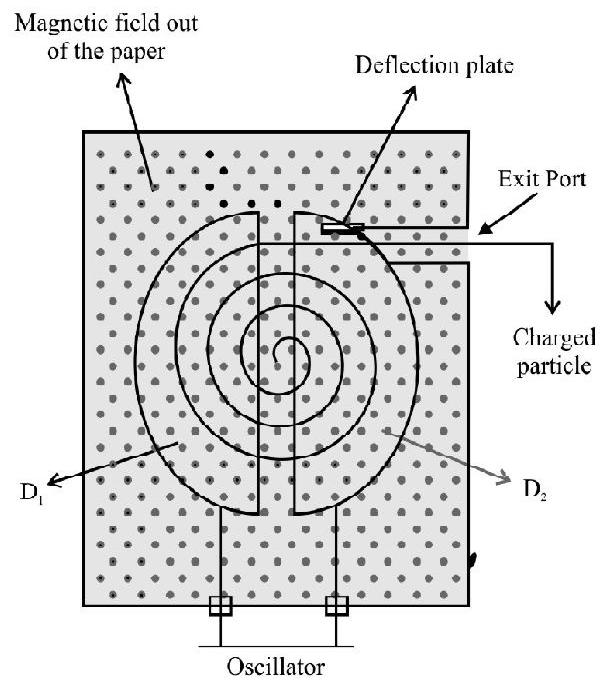
The charged particles move in a circular chamber made up of two parts called the D’s (dees). The particles, to be accelerated, are introduced into the arrangement near the centre of dees and a magnetic field transverse to their plane is applied. The dees are connected to an oscillator of frequency $(\mathrm{Be} / 2 \pi \mathrm{m})$ and this maintains the alternating potential and ions in phase. Thus every time the particles return to the gap, between the dees, they experience an accelerating push and are consequently accelerated to very high energies. Every time the particle get accelerated its velocity increases and, in order to satisfy the equilibrium condition, it must move in a circle of ever increasing radius. Thus the particle travel in a SPIRAL path. When the velocity is increased to a desired value, the particles are led outwords for their appropriate USE.
The ‘final energy’, to which the cyclotron can accelerate the charged particles is limited by the relativistic increase in mass with velocity.
Example-8 :
A cyclotron, in which flux density is 14000 gauss, is employed to accelerate the protons. How rapidly should the electric field between the dees be reversed? Given $\left(m _{p}=\mathbf{1 . 6 7} \times \mathbf{1 0}^{-27} \mathbf{~ k g}\right.$ and $\mathrm{e}=\mathbf{1 . 6} \times 16^{-19} \mathrm{C}$.
Show Answer
Solution:
We have
$ \begin{aligned} & \mathrm{f}=\frac{\mathrm{eB}}{2 \pi \mathrm{m}} \\ \therefore \quad \mathrm{f}= & \frac{1.6 \times 10^{-19} \times 14 \times 10^{3} \times 10^{-4}}{2 \times 3.146 \times 1.67 \times 10^{-27}} \mathrm{~Hz} \quad\quad\left(\because 1 \mathrm{G}=10^{-4} \mathrm{~T}\right) \\ & =21.34 \mathrm{MHz} \end{aligned} $
Force on a Current Carrying Conductor in a Magnetic Field
Since a magnetic field exerts a force on a moving change, it is clear that a magnetic field will also exerts force on a conductor carrying a current.
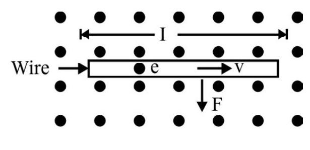
Consider a straight wire, carrying a current $i$, placed in uniform magnetic field B. The wire is kept at right angles to the field. Let $\mathrm{n}$ be the number of free electrons per unit volume and let us suppose that they have a average drift velocity $v$ in a direction perpendicular to $\mathbf{B}$. The magnitude of the average force on each electron is given by
$$ \left|\mathbf{F}^{\prime}\right|=\mathrm{ev}|\mathbf{B}| $$
Also the current density $|\mathbf{J}|=$ nev
Therefore we have $\mathrm{v}=\frac{|\mathbf{J}|}{\mathrm{ne}}$
$~$
Hence $\left|F^{\prime}\right|=\mathrm{e}|\mathbf{B}| \frac{\mathrm{j}}{\mathrm{ne}}=\frac{\mathrm{jB}}{\mathrm{n}}$
Total number of electron in a conductor of length $\mathrm{L}$ is $\mathrm{AL} \times \mathrm{n}$
Since all these electrons are moving in the same direction, in a uniform magnetic field the force is in the same direction for all the free electrons.
Thus the force $|\mathbf{F}|=$ on the whole conductor is $(\mathrm{nAL}) \times|\mathbf{F}|=\mathrm{nAL}\left(\frac{\mathrm{jB}}{\mathrm{n}}\right)=(\mathrm{Aj}) \mathrm{LB}$
$$ =\mathrm{iL}|\mathbf{B}| \quad[\because \mathrm{AJ}=\mathrm{i}] $$
However, if the current is flowing at an angle $\theta$, with respect to $\mathbf{B}$, this result can be generalized as
$$ \mathbf{F}=\mathrm{i}(\mathbf{L} \times \mathbf{B}) $$
$~$
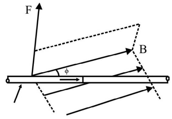
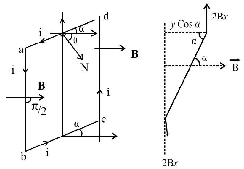
Torque on a Current Carrying Coil in a Magnetic Field
As shown in the figure let us consider a coil abcd suspended in a uniform magnetic field $\mathbf{B}$. Let the sides $a b$ and cd, of the coil, have a length $x$ and let sides bc and da have a length $y$. We denote by $\alpha$, the angle which the plane of the coil, makes with the direction of the field. Current, flowing in the coil abcd, is denoted by i.
$~$
The force on the arm da is given by iy $\mathrm{B} \sin (\pi-\alpha)=$ iy $\mathrm{B} \sin \alpha$. The direction of this force is in the plane of the coil and directed upwards.
Similarly the force on arm bd is (iy B $\sin \alpha$ ) and is in the plane of the coil and directed down wards.
These two forces do not produce any effect on the coil as they are in the same plane and oppositely directed.
Similarly the magnitude of forces acting on the sides $a b$ and cd is given by (i $x$ B)
The direction of the force on side ab and cd is perpendicular to the plane of paper directed, respectively, outwards, and into, the plane of the coil.
Since these two forces are equal parallel and act in opposite directions, and have different line of action, they consitute a torque. This torque is given by
$$ \begin{aligned} & \quad \tau=\mathrm{i} x \mathrm{~B} \times \mathrm{y} \cos \alpha \quad \qquad [\mathrm{y} \cos \alpha \text { is the arm of the couple }] \\ \text { or } & \quad \tau=\mathrm{i} A B \cos \alpha \quad ~ \quad \qquad {[A, \text { the area of the coil, equals }(x y)]} \end{aligned} $$
Le the angle, which the normal to the plane of the coil, makes with the direction of the field be $\theta$. We than have
$$ \alpha=\left(\frac{\pi}{2}-\theta\right) \text { and } \cos \alpha=\sin \theta $$
Hence torque $\tau$ is given by $\tau=\mathrm{iAB} \sin \theta$
If the coil has $n$ turns than the torque becomes $\tau=n \mathrm{AB} \sin \theta$
Taking into consideration, the direction of the torque, we can write.
$$ \boldsymbol{\tau}=\operatorname{ni}(\mathbf{A} \times \mathbf{B}) $$
Denoting $\operatorname{ni}(\mathbf{A})=\mathbf{M}$, the equivalent magnetic dipole moment of the (rectangular) coil, we can write.
$$ \boldsymbol{\tau}=(\mathbf{M} \times \mathbf{B}) $$
The tendency of this torque is to rotate the coil about its own axis and to bring it to its ’equilibrium position’, the position in which $\mathbf{M}$ is parallel to $\mathbf{B}$.
[The above expression is analogous to the expression for the couple on an electric dipole in an electrostatic field i.e.
$$ \boldsymbol{\tau}=[\mathbf{P} \times \mathbf{E}] $$
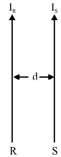
Force between two Parallel Long Current Carrying Wires
When two parallel current carrying wires are kept near to each other, each exerts a force on other. We can think of either one of the wirs as being situated in the magnetic field caused by the other current carrying wire. Hence there results a force between these current carrying conductors. To calculate this force we consider two long straight conductors $\mathrm{R}$ and $\mathrm{S}$, carrying currents $\mathrm{I} _{\mathrm{R}}$ and $\mathrm{I} _{\mathrm{S}}$, respectively, and seperated by a distance $d$. The magnetic field $B _{R}$, at the location of the conductor $S$, due to current $I _{R}$, flowing in conductor $\mathrm{R}$, is given by.
$$ \mathrm{B} _{\mathrm{R}}=\mu _{0} \frac{\mathrm{I} _{\mathrm{R}}}{2 \pi \mathrm{d}} $$
Due to this field the force on a length $L$ of the (other) conductor, carrying a current $\mathrm{I} _{\mathrm{S}}$, is given by
$$ \mathrm{F}=\mathrm{B} _{\mathrm{R}} \mathrm{I} _{\mathrm{S}} \mathrm{L} $$
Hence $F=\frac{\mu _{0} I R}{2 \pi d} \times I _{S} \times L=\frac{\mu _{0} I _{R} I _{S} L}{2 \pi d}$
$~$
The force, per unit length, therefore, equals $\left(\frac{\mu _{0} I _{R} I _{S}}{2 \pi d}\right)$
We represent below the field lines and direction of force, between two parallel curernt carrying conductors, carrying currents that are (i) LIKE and (ii) UNLIKE, currents.
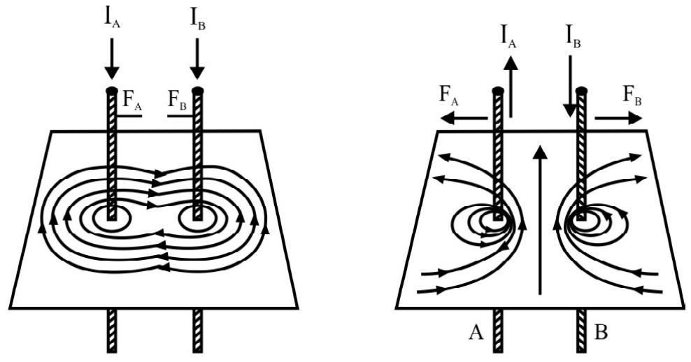
$~$
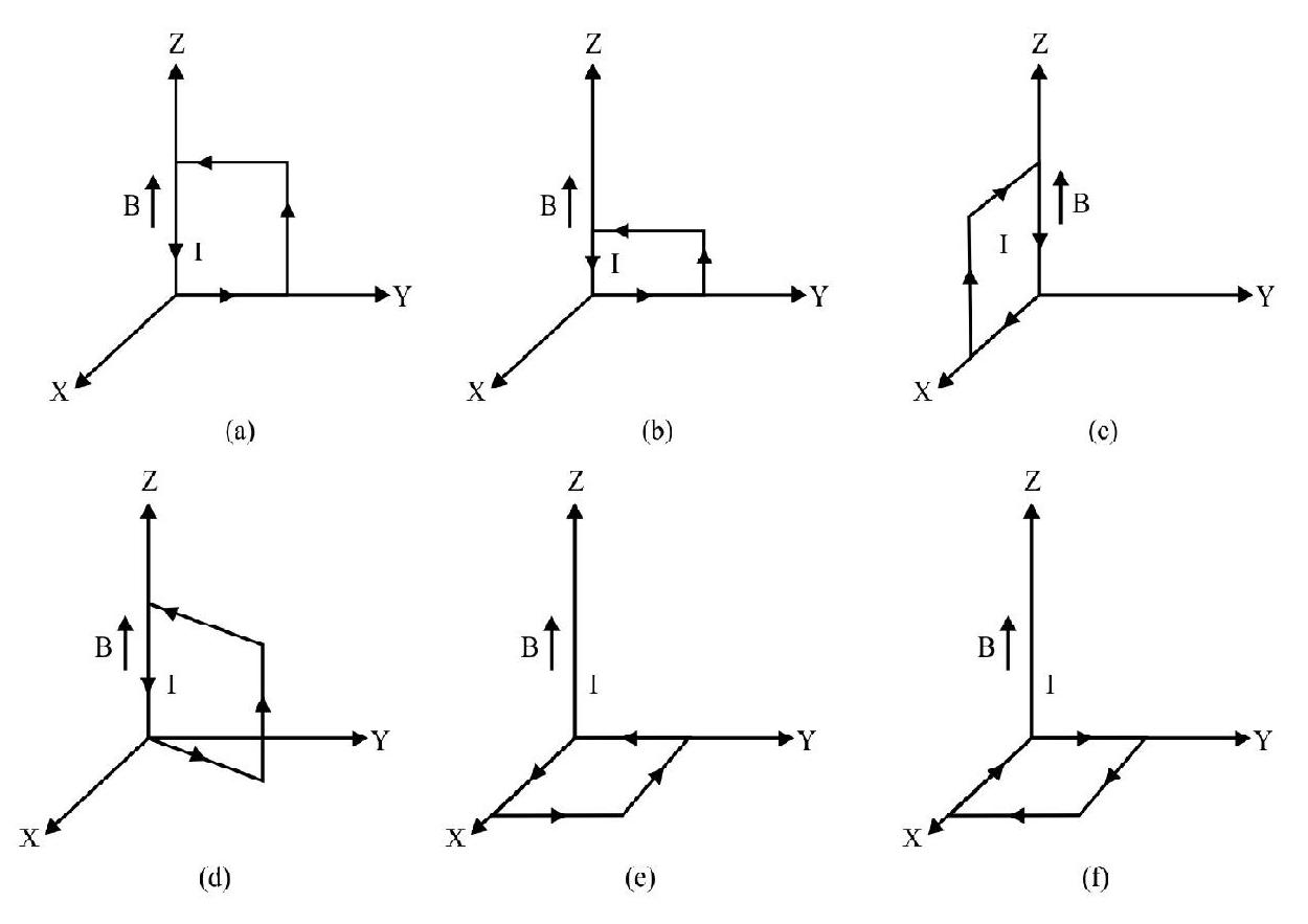
Example-9 :
A uniform magnetic field, of 3000G, is established along the positive $\mathrm{z}$ axis. A rectangular loop, of sides $10 \mathrm{~cm}$ and $5 \mathrm{~cm}$, carries a current of 12A. Find the torque on the loop, in the different cases shown in figure. Which cases corresponds to the position of equilibrium?
Show Answer
Solution:
The torque, on a current ( $=\mathrm{i}$ ) carrying loop, placed in a magnetic field $\mathbf{B}$, is given by
$$ \boldsymbol{\tau}=\mathrm{i}(\mathbf{A} \times \mathbf{B}) $$
where $A$ is the area of the loop.
We use this result for the different cases shown here.
$~$
(a) $\tau=\mathrm{iAB} \sin \theta$
$$ \begin{aligned} & =\mathrm{i} \mathrm{AB} \sin 90^{0}=\mathrm{i}(\mathrm{AB}) \\ \therefore \quad & =12 \times 0.10 \times 0.05 \times 30 \times 10^{-2} \mathrm{~N}-\mathrm{m} \quad \qquad ( \therefore 300 G = 3000 \times 10^{-4} T) \\ & =1.8 \times 10^{-2} \mathrm{Nm} \end{aligned} $$
The direction of this torque is along the negative $\mathrm{z}$ axis.
(b) Same as in (a)
(c) $1.8 \times 10^{-2} \mathrm{~N}-\mathrm{m}$ along negative $x$ direction.
(d) $1.8 \times 10^{-2}(\mathrm{~N}-\mathrm{m})$, at an angle of $270^{\circ}$, with the positive $x$ direction.
(e) In this case all the four arms all perpendicular to the field. Hence the torque is zero.
(f) The torque in this case in also zero.
It is clear that only the positions (e) and (f), for which the torque is zero, can be positions of equilibrium.
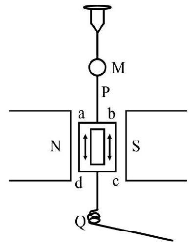
Moving Coil Galvanometer
A moving coil galvanometer makes use of the torque, on a coil, situated in a uniform magnetic field, to measure the current flowing in the wires of the coil. It consists of a rectangular coil, of $\mathrm{N}$ turns of wire, suspended by a thin phospher bronze wire $\mathrm{P}$, between the pole pieces, $\mathrm{N}$ and $\mathrm{S}$, of a permanent magnet which provides a uniform field. $\mathrm{P}$ carries a small concave mirror, $\mathrm{M}$, to measure, with ease and procision the small defletion of the coil, using a lamp and scale arrangement. Current enters and leaves the coil via suitable terminals, connected to $P$ and a fine spring, $Q$. Couple, acting on the coil due to the passage of the current i, is $\mathrm{Ni} \mathrm{AB} \cos \theta$. This couple is balanced by the restoring couple, set up due to the twist in the suspension fibre. This equals $\mathrm{k} \alpha$, where $\mathrm{k}$ is the torsional couple per unit twist.
Hence $n i \mathrm{AB} \cos \theta=\mathrm{k} \alpha$
or $\quad i=\frac{k}{n A B \cos \theta} \alpha$
$~$
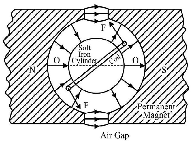
As such, the instrument will, therefore, have a non linear scale. To achieve a linear scale we use a radial magnetic field. Such a field is obtained by using a permanent magnet with cylindercal concave pole pieces coaxial with the coil, and a soft iron cylinder, kept concentric with the coil. This configuration produces a field whose flux lines are (nearly) along the extension of radii of the soft iron cylinder in the air gap between it and the concave pole pieces.

$~$
We then have $\theta=0^{0}$ and $\cos \theta=1$
$\therefore \quad \mathrm{Ni} \mathrm{AB}=\mathrm{k} \alpha$
or $\quad \therefore \mathrm{i}=\left(\frac{\mathrm{k}}{\mathrm{NAB}}\right) \alpha=\mathrm{c} \alpha$
The radial field set up thus enables us to get a linear scale. We define
$$ \frac{\mathrm{d} \alpha}{\mathrm{di}}=\frac{\mathrm{I}}{\mathrm{c}}=\frac{\mathrm{NAB}}{\mathrm{k}} $$
as ‘sensitivity’ of the galvanometer.
$~$
Example-10 :
A rectangular coil, of area $5 \times 10^{-4} \mathrm{~m}^{2}$ and having 60 turns, is pivoted about one of the vertical sides. The coil is in a radial horizonal field of $90 \mathrm{G}$. Find the torsional constant of the hair springs, connected to the coil, if a current of $0.2 \mathrm{~mA}$, produces are angular deflection of $18^{\circ}$.
Show Answer
Solution:
For equilibrium we have
$$ \text { in } \mathrm{BA}=\mathrm{c} \theta $$
where the symbols have their usual meanings.
Hence $\mathrm{c}=\frac{\text { ni BA }}{\theta}$
$$ \begin{aligned} \therefore \quad \mathrm{c}= & \frac{60 \times 0.20 \times 10^{-3} \times 90 \times 10^{-4} \times 5.0 \times^{-4}}{18} \quad \frac{(\mathrm{N}-\mathrm{m})}{\text { degree }} \\ & =3 \times 10^{-9} \mathrm{~N}-\mathrm{m} \text { per degree } \end{aligned} $$
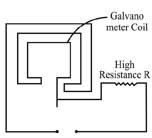
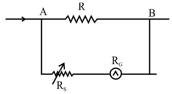
Voltmeter
$~$
Avoltmeter is nothing but a high resistance (idealy infinite) galvanometer. It is used to measure the potential difference between two points in an electrical circuit. However to measure this p.d, a small current has to flow-through the voltmeter coil. The movement of the coil, in the magnetic field, can be calihrated to read the potential difference directly. However, the current drawn by the voltmeter coil for its functioning, reduces the current across the two points of the circuit and thus the potential difference (between two points) which was to be measured gets reduced. The voltmeter, therefore does not read the ’true value’. To minimize this error, the voltmeter has to have a high resistance. (so that only a very small fraction, of the current flowing between the two points, goes into it).
We can convert a galvanometer into a voltmeter of a desired range say ( 0 to V) volts. Let $\mathrm{I} _{\mathrm{g}}$ be the maximum permissible current through the galvanometer. It is clear that if the p.d to be measured exceeds $\mathrm{I} _{\mathrm{g}} \mathrm{G}$, we must connect a suitable resistance $\mathrm{R} _{\mathrm{S}}$, in series with the galvanometer coil. The value of $\mathrm{R} _{\mathrm{S}}$ should be such that the current, through the galvanometer is still $\mathrm{I} _{\mathrm{g}}$. Thus $\mathrm{R} _{\mathrm{S}}$ is given by
$~$
$$ \begin{aligned} & \frac{\mathrm{V}}{\mathrm{R} _{\mathrm{S}}+\mathrm{G}}=\mathrm{I} _{\mathrm{S}} \\ & \therefore \quad \mathrm{R} _{\mathrm{S}}=\frac{\mathrm{V}}{\mathrm{I} _{\mathrm{g}}}-\mathrm{G} \end{aligned} $$
Example-11 :
A moving coil galvanometer has a resistance of $10 \Omega$ and gives a full scale deflection for a current of 0.01 A. How can it be converted into a voltmeter that can read up to 150 volts?
Show Answer
Solution:
In order to convert the galvanometer into a voltmeter an external resistance $\mathrm{R}$ should be connected in series with $\mathrm{G}$ so that when $150 \mathrm{~V}$ are connected across the arrangement, the current through the galvanometer is only $0.01 \mathrm{~A}$. Hence
Maximum voltage drop across $\mathrm{G}=0.01 \times 10 \mathrm{~V}=0.1 \mathrm{~V}$
$\therefore$ Voltage drop across $\mathrm{R}=(150-0.1) \mathrm{V}=149.9 \mathrm{~V}$
We thus have $0.01 \times \mathrm{R}=149.9$
$\therefore \quad \mathrm{R}=\frac{149.9}{0.01} \Omega=14990 \Omega$
We, therefore, need to connect a resistance of $14,990 \Omega$ in series with the galvanometer coil.
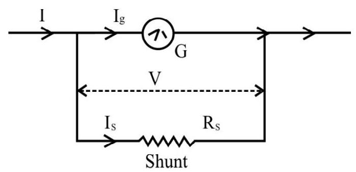
Ammeter
The ammeter is an instrument for meauring a current in an electical circuit. An ammeter is obtained by connecting a low resistance (called shunt) in parallel with a moving coil galvanometer. Hence the resistance of an ammeter is very low. To measure a current in a part of the circuit, the ammeter has to be connected in that part of the circuit and a current flows through the ammeter coil. This current carrying coil, situated in a magnetic field, consequently gets deflected and can be calibrated to read current directly in ampere’s. The ammeter is connected in series with the given circuit path, thus increasing the resistance of that path by an amount equal to the resistance of the ammeter itself. This changes the current in the path, to be measured. Obviously this change should be as low as possible, so the resistance of an ammeter has to be very small indeed! Let us see low we can convert a galvanometer of resistance any $\mathrm{G}$ into an ammeter of range ( $0-\mathrm{I}) \mathrm{A}$. To obtain this we have to shunt the galvanometer coil with a resistance $\mathrm{R} _{\mathrm{S}}$. Let $\mathrm{I} _{\mathrm{G}}$ be the maximum (permissible) curent through the galvanometer coil.

$~$
We then have $\mathrm{V}=\mathrm{I} _{\mathrm{g}} \mathrm{G}=\mathrm{I} _{\mathrm{S}} \mathrm{R} _{\mathrm{S}}$
$~$
But $I _{S}=\left(I-I _{g}\right)$
$\therefore \quad \mathrm{R} _{\mathrm{S}}=\frac{\mathrm{I} _{\mathrm{g}}}{\mathrm{I} _{\mathrm{S}}} \mathrm{G}=\left(\frac{\mathrm{I} _{\mathrm{g}}}{\mathrm{I}-\mathrm{I} _{\mathrm{g}}}\right) \mathrm{G}$
Example-12 :
A galvanometer, having 30 divisions, has a current senstivity of $20 \mu \mathrm{A} /$ division. It has a resistance of $25 \Omega$. How will you convert into an ammeter reading up to $1 \mathrm{~A}$ ?
Show Answer
Solution:
Current sensitivity $=20 \frac{\mu \mathrm{A}}{\operatorname{div}}=20 \times 10^{-6} \frac{\mathrm{A}}{\mathrm{div}}$
$\therefore \mathrm{I} _{\mathrm{g}}=$ Current for full scale deflection $=20 \times 10^{-6} \times 30 \mathrm{~A}=600 \mu \mathrm{A}$
To convert into an ammeter, of range 0 to $1 \mathrm{~A}$, the shunt required is
$$ \begin{gathered} S=\frac{I _{g}}{I-I _{g}} G=\left[\frac{6 \times 10^{-4} \times 25}{1-6 \times 10^{-4}}\right] \Omega \\ \\ ~~ =0.105 \Omega \end{gathered} $$
We, therefore, need to put a resistance of $0.105 \Omega$ in parallel with the galvanometer coil.
Magnetism
Introduction
Historically the subject of magnetism was developed from the point of view of magnetic monopoles in a way completely analogous to the concept of (positive and negative) charges, and Coulomb’s law, in electrostatics.
However, it was established later on, that monopoles do not exist. Even if we divide a bar magnet indefinitely, we do not end up with isolated poles; we always obtain a dipole. With developments in our understanding of the structure of matter, we now study magnetic phenomenon as one of the effects of current. However, Bar Magnets still have their own importance. We list some important facts in this context:
1. The earth apprears to behave like a magnet.
2. A freely suspended (isolated) bar magnet points along the North-South direction.
3. Like poles of two magnets, repel each other while unlike poles attract each other.
4. North and South poles of a bar magnet cannot be isolated.
5. We can make magnets from iron and its arrays.
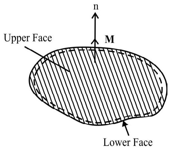
A Current Loop as a Magnetic Dipole
As shown in figure let us consider a plane loop carrying a current. With reference to its upper face, let the current be anticlockwise, as already explained, this face, then, has a North polarity. This current would appear be clockwise if we look from the lower face of the coil. Hence this face will have a South polarity. The current loop, having a north polarity at one face, and a South polarity at the other face, can, therefore, be regarded as equivalent to a magnetic dipole.
$~$
The equivalent magnetic dipole moment, of a current carrying loop, can be shown to have value $\mathrm{M}$, where.
$\mathbf{M}=\mathrm{iA}$
Here $\mathrm{i}$ is the current flowing through the loop and $\mathrm{A}$ is the area of the loop.
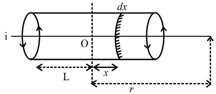
Similarity of a Current Carrying Solenoid with a Bar Magnet
We have already explained how to calculate the field of a solenoid at a point on its axis. We have seen that the field due to a small element of the solenoid, at a point, on its axis is
$~$
$$ |\mathbf{d B}|=\frac{\mu _{0} \mathrm{ia}^{2}(\mathrm{nd} x)}{\left[2(\mathrm{r}-x)^{2}+\mathrm{a}^{2}\right]^{3 / 2}} $$
For $r > > a$ and $r > > x$, the denommeter becomes of the order of $\mathrm{r}^{3}$.
$\therefore \quad \mathbf{d B} \simeq \frac{\mu _{0} \mathrm{ia}^{2}(\mathrm{nd} x)}{2 \mathrm{r}^{3}}$
Total field at (a far-off point) say $\mathrm{P}$, would then be
$ B=\frac{\mu _{0} \text { nia }^{2}}{2 r^{3}} \int _{-L}^{L} d x $
or $\quad B=\frac{\mu _{0} \text { nia }^{2}}{2 r^{3}}(2 L)$
The equivalent magnetic moment $\mathrm{M}$ of the solenoid is
$\mathrm{M}=[\mathrm{n}(2 \mathrm{~L})] \times \mathrm{i} \times\left[\pi \mathrm{a}^{2}\right]$
Hence $B=\frac{\mu _{0}}{4 \pi}\left(\frac{2 \mathrm{M}}{\mathrm{r}^{3}}\right)$
Magnetism, developed from the point of view of the pole concept, showed that the magnetic field, on the axis line of a (short) bar magnet, is also given by the above mentioned result. Also, we have already seen the similarity of the magnetic field lines of a solenoid and a bar magnet. We can, therefore, think of a current carrying solenoid as the equivalent of a bar magnet.
A Magnetic Dipole in a Uniform Magnetic Field
Let us consider a small magnetic needle of magnetic moment $\mathbf{m}$, and moment of inertia I, placed in a uniform magnetic field $\mathbf{B}$. If the needle is suspended in the field, and allowed to oscillate, then it will experience a restoring couple $\tau=\mathrm{mB} \sin \theta$.
Hence, we can write
$$ \mathrm{I} \frac{\mathrm{d}^{2} \theta}{\mathrm{dt}^{2}}=-\mathrm{mB} \sin \theta $$
For small value of $\theta$, we have $\sin \theta \approx \theta$.
$\therefore \quad \mathrm{I} \frac{\mathrm{d}^{2} \theta}{\mathrm{dt}^{2}} \simeq-\mathrm{mB} \theta$
or $\quad \frac{\mathrm{d}^{2} \theta}{\mathrm{dt}^{2}}=-\left(\frac{\mathrm{mB}}{\mathrm{I}}\right) \theta=-\omega^{2} \theta \quad\left(\right.$ where $\left.\omega=\frac{\mathrm{mB}}{\mathrm{I}}\right)$
Thus the (small amplitude) oscillations (ofa magnetic needle) are simple harnonic with a time period given by
$$ \begin{array}{r} \mathrm{T}=\frac{2 \pi}{\omega}=2 \pi \sqrt{\frac{\mathrm{I}}{\mathrm{mB}}} \\ \therefore \quad \mathrm{B}=\left(\frac{4 \pi^{2} \mathrm{I}}{\mathrm{mT}^{2}}\right) \end{array} $$
This expression is often used for an accurate determination of $\mathrm{B}$.
Proceeding, exactly on the same lines, as we studied in electrostatics, we can obtain the magnetic potential energy, $U _{m}$, of a magnet, in a magnetic field. We then have
$$ \mathrm{U} _{\mathrm{m}}=\int \tau(\theta) \mathrm{d} \theta=\int \mathrm{mB} \sin \theta \mathrm{d} \theta $$
or
$$ \mathrm{U} _{\mathrm{m}}=-\mathrm{mB} \cos \theta=-\mathbf{m} \cdot \mathbf{B} $$
Terrrestrial Magnetism
The fact, that a freely suspended magnetic needle, at any point on the surface of earth, always point in the north south direction, shows that a magnetic field exists at all points on the surface of earth. The describe the field at any point we must determine (i) the plane in which earth’s field lies and (ii) the intensity of earth’s field $\mathbf{B}$. This is generally achieved by determining the following three quantities.
(i) The ‘declination’ or the variation from true north.
(ii) The ‘inclination’ or DIP to the horizontal, of the total magnetic field of the earth.
(iii) The horizontal component of earth’s magnetic field.
These three quantities are called the Magnetic Elements of Earth.
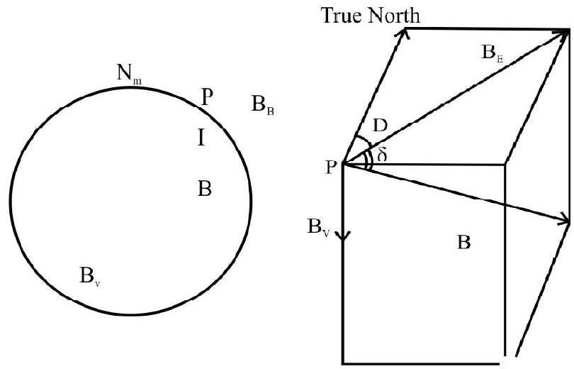
$~$
B - the earth’s magnetic field
$\mathrm{B} _{\mathrm{E}}$ - horizontal component of earth’s field
$\mathrm{B} _{\mathrm{v}}$ - the vertical component of earth’s field
$\mathrm{D}$ - the declination
$\delta$ - angle of dip
(i) Declination, at a place, is the angle between the geographical and magnetic meridian there.
(ii) The DIP is the angle between the direction of the total magnetic intensity, and the horizontal component of earth’s magnetic field.
(iii) The horizontal component of earth’s field is the component of the earth’s field along the horizontal. Denoting by $\delta$, the dip at a place and by $\mathrm{B} _{\mathrm{E}}$ and $\mathrm{B} _{\mathrm{V}}$, the horizontal and vertical components of earth’s field, we can write.
$$ \mathrm{B} _{\mathrm{E}}=\mathrm{B} \cos \delta $$
or
$$ \mathrm{B} _{\mathrm{v}}=\mathrm{B} \sin \delta $$
[ $\mathrm{B}=$ Total (Magnetic) intensity of earth’s (magnetic) field. $]$
It follows that $\tan \delta=\frac{B _{V}}{B _{E}}$
Example-13 :
A ship is sailing due east, according to the Mariner’s compass. If the declination of the place be $10^{0}$ east, what is the true direction of the ship?
Show Answer
Solution:
As the declination is $10^{\circ}$ east, the north as pointed by Mariner’s compass, will be $10^{\circ}$ east of true north. Hence the east, as shown by the compass, will be actually $10^{\circ}$ ahead, i.e., $10^{\circ}$ south of east.
Thus the true direction of the ship is $10^{\circ}$ south of east.
Magnetisation and Magnetic Intensity
We have shown that the magnetic field due to a long solenoid at a point, on its axis near its centre, is given by
$$ \mathrm{B} _{0}=\mu _{0} \mathrm{ni} $$
If the interior of the solenoid is filled will a magnetic substance then under the influence of $\mathbf{B} _{0}$, the equivalent dipoles, of the magnetic material, will set up a secondary field of their own $\left(\mathbf{B} _{\mathrm{s}}\right)$. The total field can then be written as
$$ \mathbf{B}=\mathbf{B} _{0}+\mathbf{B} _{\mathrm{s}} $$
The field, $\mathbf{B} _{\mathrm{s}}$, truns out to be proportional to the magnetisation vector $\mathbf{M}$ of the material and can be written as
$$ \mathbf{B} _{\mathrm{S}}=\mu _{0} \mathbf{M} $$
The magnetisation vector $\mathbf{M}$, of a material, equals the net magnetic dipole moment per unit volume, induced in it by the action of the (external) magnetic field ( $\mathbf{B} _{0}$, in this case).
Detailed analysis of the problem show that it is convenient to introduce a new vector $\mathbf{H}$ which is defined as
$$ \mathbf{H}=\left(\frac{\mathbf{B}}{\mu _{0}}-\mathbf{M}\right) $$
$\mathbf{H}$ can be related to the current flowing in the solenoid.
The vector $\mathbf{M}$, is of course, dependent on the nature of magnetic material. We express this fact by writing
$$ \mathbf{M}= \chi \mathbf{H} $$
$\chi$ is known as susceptibiety of the magnetic material
From above definition of $\mathbf{H}$, we get $\quad \mu _{0} \mathbf{H}+\mu _{0} \mathbf{M}=\mathbf{B}$
$$ \begin{gathered} \mathbf{B}=\mu _{0}(\mathbf{H}+\mathbf{M})=\mu _{0}(\mathbf{H}+\chi \mathbf{H}) \\ \mathbf{B}=\mu _{0} \mathbf{H}(1+\chi) \end{gathered} $$
Putting $1+\chi=\mu _{\mathrm{r}}$
We have $\mathbf{B}=\mu _{0} \mu _{\mathrm{r}} \mathbf{H}$
$\therefore \quad \mathbf{B}=\mu \mathbf{H} \quad\left(\mu=\mu _{0} \mu _{\mathrm{r}}\right)$
[For vaccum $\mu=1$ and $\mathbf{B}$ and $\mathbf{H}$ become one entity as it should be.]
Classification and Properties of Magnetic Materials
Magnetic materials are generally classified into three main categories. They are (i) Diamagnetic (ii) Paramagnetic and (iii) Ferromagnetic. We list below their characterstic properties.
1. Paramagnetic Materials
(a) In a magnetic field, the paramagnetic always move towards the region of increasing magnetic field.
(b) The magnetisation, $\mathbf{M}$, varies linearty with $\mathbf{H}$
$$ \mathbf{M}=\chi \mathbf{H} $$
$ \quad \chi$ is khown as the susceptibility of the material and is positive for paramagnetics.
(c) $\chi$ of paramagnetic varies inversely with temperature.
$$ \chi=\frac{\mathrm{c}}{\mathrm{T}} $$
where $\mathrm{c}$ is a constant and $\mathrm{T}$ is the absolute temperature. This relation, for paramagnetics, is known as CURIE’s Law.
(d) Since $\mathbf{B}=\mu _{0}(1+\chi) \mathbf{H}$ and as $\chi>0$ it follows that $\mathbf{B}>\mu _{0} \mathbf{H}$
This implies that, for paramagnetics the magnetisms field, produces magnetisation in its own direction.
(e) Since $\mu _{\mathrm{r}}=1+\chi _{\mathrm{m}}$ it follows $\mu _{\mathrm{r}}>1$
It is interesting to know that the cause of paramagnetic behaviour can be associated with materials whose atoms / molecules have net (non-zero) permanent magnetic dipole moment associated with them. Paramagnetic materials are therefore, similar to ‘Polar dielectrics’.
2. Diamagnetic Materials
(a) The diamagnetic move towards the region of decreasing field strength in a magnetic field.
(b) The relation, $\mathbf{M}=\chi \mathbf{H}$, also holds for diamagnetics. However $\chi<0$ and is a small quantity.
(c) For diamagnetics $\chi$ is (almost) independent of temperature.
(d) As $\mathbf{B}=\mu _{0}(1+\chi) \mathbf{H}$ it follows that for diamagnetics $\mathbf{B}<\mu _{0} \mathbf{H}$.
(e) It is easy to see that the permeability $\left(\mu _{\mathrm{r}}=\mu _{0}(1+\chi)\right)$, of diamagnetics, is less than 1 .
(f) Diamagnetism is a universal effect. However diamagnetism is a very week effects and it easily get masked when the material is a paramagnetics or a ferromagnetic.
(g) The atoms / molecules of a diamagnetics material do not have a net magnetic dipole moment associated with them. Diamagnetic materials are, therefore, similar to non-polar, dielectric.
3. Ferromagnetic Materials
(a) The magnetising effects, associated with ferromagnetics, are about $10^{6}$ times as large as the corresponding effects for diamagnetics or paramganetics.
(b) Unlike diamagnetics or paramagnetics, $\mathbf{M}$ of a ferromagnetic is not directly proportional to $\mathbf{H}$. $\mathbf{M}$ is now not a definate function of $\mathbf{H}$ but depends upon the previous magnetic, history internal and mechanical treatment of the speciman. This charactertics, of ferromagnetics, is known as Hystreresis.
(c) Curie’s law for ferromagnetics is
$$ \chi=\frac{\mathrm{c}}{\mathrm{T}-\theta} $$
Here, $\theta$ is a magnetic transformation temperature, known as the curie temperature. For $\mathrm{T}<\theta$, the substances behaves like a ferromagnetic and for $\mathrm{T}>\theta$, the substance behaves like a paramagnetic.
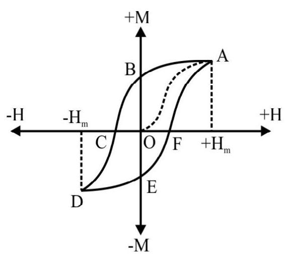
Hysteresis Curve
We now discuss the ‘Hysteresis behaviour’ of ferromagnetic substances.
In the graph shown, point $O$ corresponds to the unmagnetized state of the ferromagnetic material. The magnetisaction, $\mathrm{M}$, at first increases with increasing field. Point Acorresponds to the state when magnetisation reaches a satutation value (corresponding to a field $\mathrm{H} _{\mathrm{m}}$ ). If the applied field is now decreased, in steps, the points, corresponding to the curve $\mathrm{AB}$, are obtained. It is seen that at point $\mathrm{B}$ the field has become zero but the (ferromagnetic) material is still (strongly) magnetised. This shows that $\mathbf{M}$ is lagging behind $\mathbf{H}$. On reversing the field, and numerically increasing it in step, it is seen that $|\mathbf{M}|$ reaches zero, at some point $C$ (corresponding to some reversed value of $\mathbf{H}$ ). On increasing the field, in reverse direction, the portion CD is obtained. On reversing the field again, we get the portion DE, EF and FA of the complete loop. If the field be now varied cyclically, between the values $\mathrm{H} _{\mathrm{m}}$ and $-\mathrm{H} _{\mathrm{m}}$, the curve ABCDEFA is obtained. The curve ABCDEFA shows that $\mathbf{M}$ is always lagging behind $\mathbf{H}$. This phenomenon (of $\mathbf{M}$ lagging behind $\mathbf{H}$ ) is known as hysteresis. The curve (ABCDEFA) known as a hysteresis loop.
The point $\mathrm{B}$, representing the retained or residual magnetisation, is known as the retentinty of the material. The (reverse) magnetic field at the point $\mathrm{D}$, for which the material gets completely demagnetised, is known as the coearcivity.
$~$
PROBLEMS FOR PRACTICE
1. Find the magnetic field at the centre of a regnlar hexagon of side $h$ canying a current $i$.
Show Answer
Answer: $\sqrt{3}\left[\frac{\mu _{0} \mathrm{i}}{\pi \mathrm{h}}\right]$2. An equilaterial triangle is formed from a uniform wire. If the current enters and leaves at the two corners, of a side of the triangle, show that the magnetic field at the centre of the triangle is zero.
3. Calculate the magnetic field, at a point distant $2 \mathrm{~m}$, on the axis of a circular coil, of radius I $\mathrm{mm}$, carrying a current of $0.5 \mathrm{~A}$.
Show Answer
Answer: $0.393 \times 10^{-15} \mathrm{wb} / \mathrm{m}^{2}$4. A circular coil, of radius $2 \mathrm{~cm}$, is concentric and coplaner with a circular coil of radius $7 \mathrm{~cm}$. Each coil has 100 turns. With a current of 5A in thelarger coil, find the current needed, in the smaller coil, to give zero magnetic field at the common centre of the two coils.
Show Answer
Answer: 143 A in the opposite direction5. Considering two parallel co-axial circular coils, of equal radius $\mathrm{R}$, and equal number of turns $\mathrm{N}$, carrying equal currents in the same direction, and seperated by a distance $\mathrm{R}$, show that the field on the axis, around the midpoint between the two coils, is (nearly) uniform over a distance that is small compared to $\mathrm{R}$; and its magnitude is given by
Show Answer
Answer: $B \approx\left(0.72 \frac{\mu _{0} \mathrm{i}}{\mathrm{R}}\right)$6. A solenoid has 400 turns, of wire wound on a cylinder of radius $5 \mathrm{~cm}$ and length $40 \mathrm{~cm}$. Calculate the magnetic field at the (a) midpoint of the solenoid and (b) a point, on the axis, $2 \mathrm{~cm}$ from one end, of the solenoid, when a current of 1 A flows through it.
Show Answer
Answer: (a) $1.219 \times 10^{-3} \mathrm{wb} / \mathrm{m}^{2}$ , (b) $0.3905 \times 10^{-3} \mathrm{wb} / \mathrm{m}^{2}$7. Two short solenoids, each of radius $6 \mathrm{~cm}$ and length $13 \mathrm{~cm}$, uniformly wound with 30 turns of wire per $\mathrm{cm}$, are placed co-axially with a gap of $6 \mathrm{~cm}$ between then. If these are connected in series. FInd the magnetic field, at the centre of the gap, due to a current of 1A through the combination.
Show Answer
Answer: $1.8 \times 10^{-2} \mathrm{wb} / \mathrm{m}^{2}$8. A long wire, carries a current of $20 \mathrm{~A}$ along the axis of a long solenoid. The field due to the solenoid is $4 \mathrm{mT}$ at a point distance $3 \mathrm{~cm}$ from its axis. Find the resultant field at this point.
Show Answer
Answer: $4.2 \mathrm{mT}, 18.4^{0}$ with the axis of the solenoid9. An electron beam, passes through a transverse magnetic field of $2 \times 10^{-3} \mathrm{~T}$, and an electric field (also transverse) of $3.4 \times 10^{4} \mathrm{Vm}^{-1}$, both acting simultaneously. If the path of the beam remains undeviated. Calculate the speed of the electrons.
Show Answer
Answer: $7 \times 10^{7} \mathrm{~m} / \mathrm{s}$10. After being accelerated through a potential difference of 10,000 votl, an alpha particle moves in a circle of radius $50 \mathrm{~cm}$, in a magnetic field. Calculate the magnitude of the field.
(Given $\mathrm{M} _{\alpha}=6.68 \times 10^{-27} \mathrm{~kg}$ )
Show Answer
Answer: $4.09 \times 10^{-2} \mathrm{~T}$11. Deutrons are to be accelerated in a cyclotron. The value of the uniform magnetic field is $4.4 \mathrm{wb} / \mathrm{m}^{2}$. Find the period of revolution of the deutron (given mass of the deutron is $3.3 \times 10^{-27} \mathrm{~kg}$ ).
Show Answer
Answer: $2.946 \times 10^{-8} \mathrm{~S}$12. If protons are to be accelerated in a cyclotron (i) What should be the frequency of the alternating potential difference applied. (ii) How much energy will a proton acquire after 50 revelutions? The p.d. across the dees is $10^{5}$ volts and the applied field is $1.5 \mathrm{wb} / \mathrm{m}^{2}$. Given $\mathrm{m} _{\mathrm{p}}=1.1 \times 10^{-27} \mathrm{Kg}$.
Show Answer
Answer: (i) $2.24 \times 10^{7} \mathrm{~Hz}$, (ii) $1.6 \times 10^{-12} \mathrm{~J}$13. Two straight wire, each $10 \mathrm{~cm}$ long, are parallel to one another and seperated by a distance of $2 \mathrm{~cm}$. They carry currents, of $30 \mathrm{~A}$ and $40 \mathrm{~A}$, respectively. calculate the force experienced by either of the wire.
Show Answer
Answer: $1.2 \times 10^{-3} \mathrm{~N}$14. Find the force in kgwt, per decimeter length, between two conductors, spaced $4 \mathrm{~cm}$ apart, and carrying currents of $2000 \mathrm{~A}$ and $4000 \mathrm{~A}$, respectively. (Take of $\mathrm{g} \simeq 10 \mathrm{~ms}^{-2}$ )
Show Answer
Answer: $1.2 \times 10^{-3} \mathrm{~N}$15. A100 turn, closely wound circular coil, of mean radius $10 \mathrm{~cm}$, carries a current of $3.2 \mathrm{~A}$. The coil is placed in a vertical plane and is free to rotate about a horizontal direction which coinsides with its diameter. Auniform magnetic field, of $2 \mathrm{~T}$, in the horizontal direction, exists such that, initially, the axis of the coil is in the direction of the field. The coil rotates through an angle of $90^{\circ}$ under the influence of the magnetic field. Calculate the torque in the initial and final position of the coil.
Show Answer
Answer: zero, $20 \mathrm{~N}-\mathrm{m}$16. A rectangular coil, of sides $8 \mathrm{~cm}$ and $6 \mathrm{~cm}$, having 2000 turns and carrying a current of $200 \mathrm{~mA}$, is placed in a uniform magnetic field of 0.2 directed along the positive $x$ axis. Calculate the maximum torque the coil can experience.
Show Answer
Answer: $0.384 \mathrm{~N}-\mathrm{m}$17. A regtangular coil, of area $5.0 \times 10^{-4} \mathrm{~m}^{2}$, and 90 turns, is free to rotate about one of its vertical sides. The coil is in a radial magnetic field of $60 \times 10^{-4} \mathrm{~T}$. Calculate the torisonal constant of the springs, attached to the coil, if a current of $0.20 \times 10^{-3} \mathrm{~A}$ produces on angular displacement of $\pi / 10$ radins.
Show Answer
Answer: $3 \times 10^{-9}(\mathrm{~N}-\mathrm{m})$ per Degree20. A glavanometer is placed in a radial magnetic field of $9.2 \mathrm{wb} / \mathrm{m}^{2}$. The coil of the galvanometer has 200 turns and its area is $1.6 \times 10^{-4} \mathrm{~m}^{2}$. The restoring torsional constant, of the suspension fibre, is $10^{-6} \mathrm{Nm} /$ degree. Calculate the maximumm current that can be measured by this galvanometer if the scale can accomodule up to $45^{\circ}$ deflection.
Show Answer
Answer: $7 \times 10^{-4} \mathrm{~A}$21. A rectangular coil, of area $10^{2} \mathrm{~m}^{2}$, is suspended in a radial magnetic field $5 \times 10^{-2} \mathrm{wb} / \mathrm{m}^{2}$. What current should be made to pass through it to keep it in equilibrium at an angle of $30^{\circ}$ with the field? [Given that the restroing couple per unit twist of the suspension fibre is $10^{-8}(\mathrm{~N}-\mathrm{m} /$ degree $)$ ].
Show Answer
Answer: $6 \times 10^{-4} \mathrm{~A}$22. A voltmeter, which deflects full scale for a potential difference of $5.0 \mathrm{~V}$, across it is to be made by connecting a resistance $\mathrm{R}$ in series with a galvanometer. The $80 \Omega$ galvanometer deflects full scale for a potential of $20 \mathrm{mV}$ across it. Calculate $\mathrm{R}$.
Show Answer
Answer: $19.92 \mathrm{k} \Omega$23. A galvanometer, with a resistance of $12 \Omega$, shows full scale deflection for a current of $0.0025 \mathrm{~A}$. How can it be converted into a voltmeter of range 0 to $10 \mathrm{~V}$ ?
Show Answer
Answer: Connect a $3988 \Omega$ resistor in series.24. A120V, d.c. source, is connected across series combination of a large resistance $R$ and voltmeter, of resistance $10000 \Omega$. If the voltmeter reads $4 \mathrm{~V}$, calculate the value of $R$.
Show Answer
Answer: $290 \mathrm{k} \Omega$25. A galvanometer needs a current of $1 \mathrm{~mA}$ for full scale deflection. What is the resistance of the shunt needed to convert into an ammeter reading up to $1 \mathrm{~A}$.
Show Answer
Answer: $5 \times 10^{-3} \Omega$26. A galvanometer with a resistance of $12 \Omega$ shows full scale deflection for a current of $2.5 \mathrm{~mA}$. How will you convert it an ammeter of range $0-7.5 \mathrm{~A}$ ?
Show Answer
Answer: $0.004 \Omega$27. A galvanometer of resistance $20 \Omega$ needs a current of $50 \mathrm{~mA}$ for full scale deflection. How it can be converted into an ammeter of range (0-10)A.
Show Answer
Answer: $0.1 \Omega$28. In the magnetic meridian of a place $\mathrm{P}$, the horizontal compoent of the earth’s magnetic field is 0.26 gauss and the dip angle is $60^{\circ}$. What is the total magnetic field of earth at this location?
29. The horizontal component of earth’s magnetic field, at a certain place is $3 \times 10^{-5} \mathrm{~T}$ and the direction of the field is from geographic south to geographic north. A very long cylinder straight conductor is carrying a stready current of $1 \mathrm{~A}$. What is the force per unit length on it when it is placed on a horizontal table and the direction of the current is
(i) east to west and
(ii) south to north
Show Answer
Answer: (i) $3 \times 10^{-5} \mathrm{Nm}^{-1}$ (ii) zero30. A current of $2 \mathrm{~A}$ flows through $10^{4}$ turns of an insulated wire, wound uniformly around an iron anclor ring of radius $0.1 \mathrm{~m}$. If permeability of iron is 2000 , calculate the magnetic flux through the ring.
Show Answer
Answer: 80 SI UnitsQuestion Bank
Key Learning Points
1. Biot and Savart law is mathematically expressed by the equation.
$$ |\mathrm{d} \mathbf{B}|=\mathrm{k} \frac{\mathrm{id} \ell \sin \theta}{\mathrm{r}^{2}} $$
The constant of proportionality depends on the system of units. In the S.I system of units $K=\frac{\mu _{0}}{4 \pi}$
where $\mu _{0}$ is a constant of free space and its value is $4 \pi \times 10^{-7} \frac{\text { weber }}{\text { ampere }- \text { meter }}$.
2. We can write expression for $\mathrm{d} \mathbf{B}$ in vector rotation as
$$ \mathrm{d} \mathbf{B}=\frac{\mu _{0}}{4 \pi} \frac{\mathrm{id} \ell \times \mathbf{r}}{\mathrm{r}^{3}} $$
3. The magnetic field due to a infinite straight wire carrying a current is given by
$$ \mathbf{B}=\frac{\mu _{0} \mathrm{i}}{2 \pi \mathrm{r}}\left(\frac{\mathrm{wb}}{\mathrm{m}^{2}}\right) $$
4. The magnetic field, due a circular coil of radius a, carrying a current $i$ at its centre is given by
$$ \mathbf{B}=\frac{\mu _{0} \mathrm{i}}{2 \mathrm{a}}\left(\frac{\mathrm{wb}}{\mathrm{m}^{2}}\right) $$
and at a point on the axis of the coil at a distance $x$ from its centre is given by
$$ \mathbf{B}=\frac{\mu _{0} \mathrm{i}}{2} \frac{\mathrm{a}^{2}}{\left(\mathrm{a}^{2}+x^{2}\right)^{3 / 2}}\left(\frac{\mathrm{wb}}{\mathrm{m}^{2}}\right) $$
5. The magnetic field due to a straight solenoid at any point $\mathrm{P}$ (but near the end points) given by
$$ \mathbf{B}=\frac{\mu _{0} \mathrm{Ni}}{\mathrm{L}}\left(\frac{\mathrm{wb}}{\mathrm{m}^{2}}\right) $$
6. At far off points, a circular coil behaves as a dipole of moment $\mathbf{m}$ wheere m equals the product of the current flowing and the area of the coil. The value of $\mathbf{m}$ must be regarded as directed normal to the plane of the coil and in the sense of a right handed scrow rotated in the direction of the flow of current.
7. We can generalize the above equality for a plane current loop of any orbitrary shape.
A program to give wings to girls students
8. According to Ampere’s circuital thorem the line intergral of magnetic field around any closed cuve is equal to $\mu _{0}$ time the total current I enclosed by the closed curve viz.
$$ \oint \mathbf{B} \cdot \mathbf{d} \ell=\mu _{0} \mathrm{I} $$
9. One can use Ampere’s circuital a theorem to calculate the magnetic field due to a long straight solenoid and a toreidal solenoid.
10. Ampere’s circuital theorem
$$ \oint \mathbf{B} \cdot \mathbf{d} \ell=\mu _{0} \mathrm{I} $$
straight forwardly tells us that mangetic field is a non conservative field.
11. The force experienced by a charged particle when it is moving with a velocity $v$ making angle $\theta$ with the direction of $\mathbf{B}$ is given by
$$ \mathbf{F} _{\mathrm{B}}=\mathrm{q}(\mathbf{v} \times \mathbf{B}) $$
12. The force experienced by a charged particle when it is moving in an electric field is given by $\mathbf{F}=\mathrm{e} \mathbf{E}$ and is indepedent of the velocity with which the charged particle is moving.
13. The forced acting on a charged particle simultaneously being acted upon by a electric as well as a magnetic field as given by
$$ \mathbf{F} _{\mathrm{L}}=\mathrm{q} \mathbf{E}+\mathrm{q}(\mathbf{v} \times \mathbf{B}) $$
and is known as Lorentz force.
14. Mathematically the magnetic field vector $\mathbf{B}$ is defined through the relation
$$ \mathbf{B}=\frac{\mathbf{F}}{\mathrm{qv} \sin \theta} $$
The unit of $\mathbf{B}$ is newton per coulomb meter per second or weber $/$ meter $^{2}$ or tesla.
15. A current carrying conductor placed in a magnetic field experiences a force given by
$$ \mathbf{F}=\mathrm{i}(\mathbf{L} \times \mathbf{B}) $$
16. A plane rectangular coil of $\mathrm{N}$ turns, carrying a current $\mathrm{I}$, experiences a torque when placed in a uniform magnetic field which is given by
$$ \tau=(\mathbf{m} \times \mathbf{B}) $$
17. Force between two parallel long current carrying wires is given by
$$ \mu _{0} \frac{\mathrm{I} _{\mathrm{R}} \mathrm{I} _{\mathrm{S}} \mathrm{L}}{2 \pi \mathrm{d}} $$
where $I _{R}$ and $I _{S}$ are the current flowing respectively in two long wires of length $L$ and seperated by a distance d.
18. A moving coil galvanometer is essentially based on the fact that a rectangular coil placed in a uniform magnetic field experiences a couple. When a current is passed through it this couple is balanced by a restoring couple due to the twist in suspension wire of the galvanometer.
i.e. $\mathrm{Ni} \mathrm{AB} \cos \theta=\mathrm{k} \theta$
or $\quad i=\frac{k \theta}{\mathrm{NAB} \cos \theta}$
19. We use a radial magnetic field to provide a linear scale for the measurements by the galvanometer.
20. A voltmeter is a converted galvonometer with a very high resistance (ideally infinite) in series with the galvanometer.
21. An ammeter is a shunted low resistance (ideally tending to zero) galvanometer
22. The earth behaves as a magnet.
23. A freely suspended bar magnet points in the north south pole direction.
24. Like poles repel each other while unlike poles attract each other.
25. North and south poles of a bar magnet can not be isolated.
26. A current loop behaves as a magnetic dipole.
27. The magnetic field lines of a bar magnet and a solenoid have a similar pattern.
28. We define the following three quantities to understand the behaviour of earth’s magnetism.
(i) The declination
(ii) The dip
and (iii) The horizontal component of earth’s magnetic field.
29. Just as in electrostatic we define a magnetisation vector $\mathbf{M}$ in the study of the behaviour of magnetic materials.
30. We also define a vector $\mathbf{H}$ by the relation
$$ \mathbf{H}=\frac{\mathbf{B}}{\mu _{0}}-\mathbf{M} $$
which further enable us to define a relation.
$$ \mathbf{B}=\mu _{0}(\mathbf{H}+\mathbf{M}) $$
31. The magnetic materials can be classified as
(i) Paramagnetics
(ii) Diamagnetics
and (iii) Ferromagnetics
Average
Biot-Savart Law
1. A straight wire, carrying a current $I$, is located along the $y$-axis. The magnetic field, $\mathrm{dB}$, at$a$ (field) point $(a, b, c)$ due to a general element, $d \ell$, of this straight wire, can be written as
(1) $d \mathbf{B}=\frac{\mu _{0}}{4 \pi} I\left[\frac{(d y \hat{j}) \times(a \hat{i}+(b-y) \hat{j}+c \hat{k})}{\left(a^{2}+(b-y)^{2}+c^{2}\right)^{3 / 2}}\right]$
(2) $d \mathbf{B}=\frac{\mu _{0}}{4 \pi} I\left[\frac{(d y \hat{j}) \times(a \hat{i}+b \hat{j}+c \hat{k})}{\left(a^{2}+b^{2}+c^{2}\right)^{3 / 2}}\right]$
(3) $ d \mathbf{B}=\frac{\mu _{0} I}{4 \pi}\left[\frac{(d y \hat{j}) \times(a \hat{i}+(b-y) \hat{j}+c \hat{k})}{\left[a^{2}+(b-y)^{2}+c^{2}\right]}\right] $
(4) $d \mathbf{B}=\frac{\mu _{0} I}{4 \pi}\left[\frac{(d y \hat{j}) \times(a \hat{i}+b \hat{j}+c \hat{k})}{\left(a^{2}+b^{2}+c^{2}\right)}\right]$
Show Answer
Correct Answer: (1)
Solution:
We need to use Biot-Savart Law.
$$ \mathrm{d} \mathbf{B}=\frac{\mu _{0} \mathrm{I}}{4 \pi} \frac{\mathrm{d} \ell \times \mathbf{r}}{|\mathbf{r}|^{3}} $$
Here $\mathrm{d} \ell$, general current element, can be considered to be located at a general point $(0, \mathrm{y}, 0)$, on the $\mathrm{y}$-axis. Also since the wire lies along the $\mathrm{y}$-axis, we can write $\mathrm{d} \ell=(\mathrm{dy}) \hat{\mathrm{j}}$
The vector $\mathbf{r}$, in the Biot-Savart law, is the position vector of the field point ( $a, b, c)$, with respect to the point $(0, y, 0)$ where the current element is located. Hence
$ \mathbf{r}=(\mathrm{a}-0) \hat{\mathrm{i}}+(\mathrm{b}-\mathrm{y}) \hat{\mathrm{j}}+(\mathrm{c}-0) \hat{\mathrm{k}} $
and $|\mathbf{r}|=\left[\mathrm{a}^{2}+(\mathrm{b}-\mathrm{y})^{2}+\mathrm{c}^{2}\right]^{1 / 2}$
$\therefore \quad d \mathbf{B}=\frac{\mu _{0}}{4 \pi} I \frac{(d y \hat{j}) \times(a \hat{i}+(b-y) \hat{j}+c \hat{k})}{\left(a^{2}+(b-y)^{2}+c^{2}\right)^{3 / 2}}$
Hence option(1) is correct
Average
Magnetic Field due to Straight Current Carrying Conductor
2. A straight wire, $\mathbf{A B}$ carries a current $I$; the ends of the wire subtends angles $\theta _{1}$ and $\theta _{2}$, at point $P$, as shown in figure. The magnetic field, at point $P$, is given by
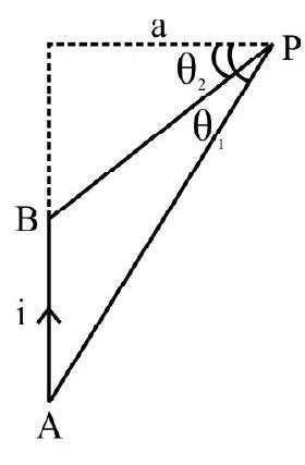 $~$
$~$
(1) $\frac{\mu _{0} \mathrm{I}}{4 \pi \mathrm{a}}\left(\sin \theta _{1}-\sin \theta _{2}\right)$
(2) $\frac{\mu _{0} \mathrm{I}}{4 \pi \mathrm{a}}\left(\sin \theta _{1}+\sin \theta _{2}\right)$
(3) $\frac{\mu _{0} \mathrm{I}}{4 \pi \mathrm{a}}\left(\cos \theta _{1}-\cos \theta _{2}\right)$
(4) $\frac{\mu _{0} \mathrm{I}}{4 \pi \mathrm{a}}\left(\cos \theta _{1}+\cos \theta _{2}\right)$
Show Answer
Correct Answer: (1)
Solution:
The magnetic field, at a distance ’ $a$ ‘, from a current carrying straight wire, is given by
$ \mathrm{B}=\frac{\mu _{0} \mathrm{I}}{4 \pi \mathrm{a}}\left(\sin \theta _{1}+\sin \theta _{2}\right) $
Here $\theta _{1}=\theta _{1}$
$ \theta _{2}=-\theta _{2}$
$\Rightarrow \mathrm{B}=\frac{\mu _{0} \mathrm{I}}{4 \pi \mathrm{a}}\left(\sin \theta _{1}-\sin \theta _{2}\right)$
Hence correct option is (1)
Average
Magnetic Field due to Straight Current Carrying Conductor
3. Equal currents, of value 1A, are allowed to flow through a sequence of long wires, parallel to $y$-axis and located at, $x=1 \mathrm{~m}, 2 \mathrm{~m}, 4 \mathrm{~m}$ and so on. If the currents flow in opposite directions in alternate wires, the value of magnetic field at the origin, $O$, is
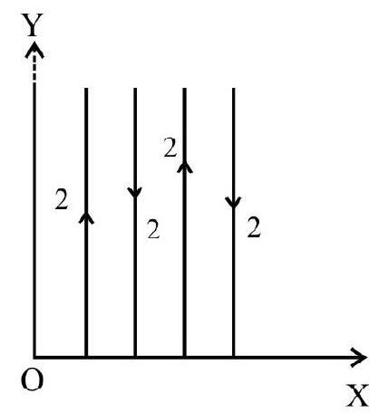
$~$
(1) $\frac{\mu _{0} \mathrm{i}}{3 \pi}$ along $z$-axis
(2) $\frac{3 \mu _{0} \mathrm{i}}{4 \pi}$ along $x$-axis
(3) $\frac{\mathrm{i}}{4 \pi / \mu _{0}}$ along $\mathrm{z}$-axis
(4) $\frac{\mu _{0} \mathrm{i}}{3 \pi}$ along $x$-axis
Show Answer
Correct Answer: (1)
Solution:
We know that the field at $\mathrm{O}$, due to current $\mathrm{i}$ through one wire, is
$$ |\mathbf{B}|=\frac{\mu _{0} \mathrm{i}}{2 \pi \mathrm{d}} $$
Hence, for the whole sequence of wires, the desired field is
$$ \begin{aligned} & \mathbf{B}=\frac{\mu _{0} \mathrm{i}}{2 \pi}\left[\left(1+\frac{1}{4}+\frac{1}{16}+\ldots . .\right) \hat{\mathrm{k}}-\left(\frac{1}{2}+\frac{1}{8}+\ldots . .\right) \hat{\mathrm{k}}\right] \\ &=\frac{\mu _{0} \mathrm{i}}{2 \pi}\left[\frac{1}{(1-4)} \hat{\mathrm{k}}-\frac{1}{2} \frac{1}{\left(1-\frac{1}{4}\right)} \hat{\mathrm{k}}\right] \\ &=\frac{\mu _{0} \mathrm{i}}{3 \pi} \hat{\mathrm{k}} \end{aligned} $$
Hence option(1) is correct
Easy
Mangetic Field due to Current Carrying Conductor
4. A conductor, in the shape of a square of edge length $\ell=0.4 \mathrm{~m}$; carries a current of $10 \mathrm{~A}$. Now this conductor is formed into a single circular turn and carries the same current. The difference of magnetic fields, produced in two cases, at the respective centres, will be.
(1) $10.5 \mu \mathrm{T}$
(2) $24.7 \mu \mathrm{T}$
(3) $3.6 \mu \mathrm{T}$
(4) $20.4 \mu \mathrm{T}$
Show Answer
Correct Answer: (3)
Solution:
Magnetic field at the centre ’ $\mathrm{O}$ ’ of the current carrying square loop.
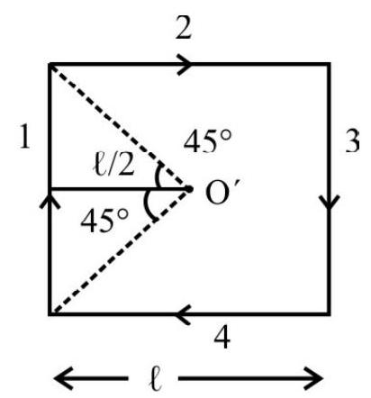
$~$
$$ \begin{aligned} \mathbf{B}= & \mathbf{B} _{1}+\mathbf{B} _{2}+\mathbf{B} _{3}+\mathbf{B} _{4} \\ & =4 \times \mathbf{B} _{1} \\ & =4 \times \frac{\mu _{0} \mathrm{I}}{4 \pi(\ell / 2)}\left(\sin 45^{0}+\sin 45^{\circ}\right) \\ \mathrm{B}= & \frac{2 \sqrt{2} \mu _{0} \mathrm{i}}{\pi \ell}=28.3 \mu \mathrm{T}(\text { inward }) \end{aligned} $$
Now, when wire is bent-into circular loop of single turn.
$$ B=\frac{\mu _{0} i}{2 a} $$
where ’ $a$ ’ is the radius of the circular loop.
$$ 2 \pi \mathrm{a}=4 \ell \Rightarrow \mathrm{a}=\frac{2 \ell}{\pi} $$
$\therefore \quad B^{\prime}=\frac{\pi \mu _{0} \mathrm{i}}{2 \ell}=24.7 \mu \mathrm{T}$ (inward)
Hence difference of magnetic fields $\Delta \mathrm{B}=\left(\mathrm{B}-\mathrm{B}^{\prime}\right)$
$$ =3.6 \mu \mathrm{T} $$
Hence option(3) is correct
Average
Magnetic Field due to Straight Conductor
5. Two long parallel transmission lines, $40.0 \mathrm{~cm}$ apart carry $25 \mathrm{~A}$ and $75 \mathrm{~A}$ current. The ratio of the distances (from the conductor carrying current of $25 \mathrm{~A}$ ), where the net mangetic field is zero, when the two lines carry current in (i) same direction and (ii) in opposite diretions, will be:
(1) $1: 1$
(2) $2: 1$
(3) $1: 2$
(4) $3: 1$
Show Answer
Correct Answer: (3)
Solution:
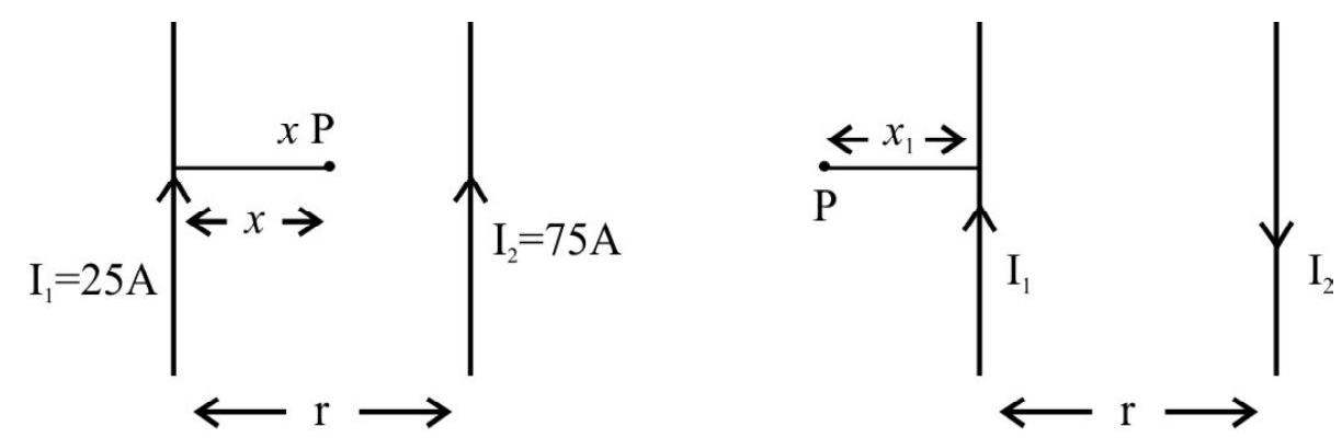
$~$
Magnetic field at point $\mathrm{P}$
$$ \begin{aligned} \mathrm{B}=\frac{\mu _{0} \mathrm{i}}{2 \pi x} & -\frac{\mu _{0} \mathrm{I} _{2}}{2 \pi(\mathrm{r}-x)}=0 & \frac{\mathrm{I} _{1}}{x _{1}}=\frac{\mathrm{I} _{2}}{\left(\mathrm{r}+x _{1}\right)} \\ \frac{\mathrm{I} _{1}}{x} & =\frac{\mathrm{I} _{2}}{(\mathrm{r}-x)} & \frac{\mathrm{I} _{1}}{\mathrm{I} _{2}}=\frac{x _{1}}{\left(\mathrm{r}+x _{1}\right)} \\ \frac{25}{x} & =\frac{75}{\mathrm{r}-x} & \frac{1}{3}=\frac{x _{1}}{\left(40+x _{1}\right)} \\ 3 x & =\mathrm{r}-x & x _{1}=20 \mathrm{~cm} \\ 4 x & =\mathrm{r}=40.0 & \\ \Rightarrow x & =10 \mathrm{~cm} & \end{aligned} $$
$\therefore \quad$ Ratio $\frac{x}{x _{1}}=\frac{10}{20}=1: 2$
Hence option(3) is correct
Average
Magnetic Field due to a Current Carrying Conductor
6. Four long parallel conductors carry equal currents of 5.0A. The direction of current is into the plane of the page at points $A$ and $B$, and out of the page at $C$ and $D$. The magnitude and direction of the magnetic field at point $P$, located at the centre of the square, will be:
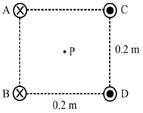
$~$
(1) $20 \mu \mathrm{T}$ downward
(2) $10 \mu \mathrm{T}$ upwards
(3) $10 \mu \mathrm{T}$ downward
(4) $20 \mu \mathrm{T}$ upwards
Show Answer
Solution:
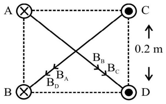
$~$
$\mathrm{B} _{\mathrm{A}}=\mathrm{B} _{\mathrm{B}}=\mathrm{B} _{C}=\mathrm{B} _{\mathrm{D}}=\frac{\mu _{0} 2 \mathrm{I}}{4 \pi \mathrm{r}}=\frac{10^{-7} \times 2 \times 5 \sqrt{2}}{0.2}=5 \sqrt{2} \times 10^{-6} \mathrm{~T}$
(Here $\mathrm{I}=5 \mathrm{~A}, \mathrm{r}=\frac{\mathrm{a}}{\sqrt{2}}=\frac{0.2 \mathrm{~m}}{\sqrt{2}}=0.14 \mathrm{~m}$ )
Net magnetic field at point $\mathrm{P}$.
$$ \begin{aligned} \mathrm{B}=\sqrt{\left(\mathrm{B} _{\mathrm{A}}+\mathrm{B} _{\mathrm{D}}\right)^{2}+\left(\mathrm{B} _{\mathrm{B}}+\mathrm{B} _{\mathrm{C}}\right)^{2}} & =\sqrt{\left(2 \mathrm{~B} _{\mathrm{A}}\right)^{2}+\left(2 \mathrm{~B} _{\mathrm{B}}\right)^{2}} \\ & =2 \times \sqrt{2} \mathrm{~B} _{\mathrm{A}} \\ & =2 \times \sqrt{2} \times 5 \sqrt{2} \times 10^{-6} \mathrm{~T} \\ & =20 \mu \mathrm{T} \text { downward } \end{aligned} $$
Hence option (1) is correct
Difficult
Magnetic Field due to Straight Current Carrying Conductor
7. A regular polygon of $n$-sides is formed by bending a wire of total length $2 \pi \mathrm{r}$. If this wire now carries a current $i$, the magnetic field $B$, at the centre of this polygon, would be
(1) $\frac{\mu _{0} \mathrm{in}^{2} \sin ^{2}(\pi / n)}{2 \mathrm{r}^{2} \pi \cos (\pi / \mathrm{n})}$
(2) $\frac{\mu _{0} \mathrm{in}^{2} \cos ^{2}(\pi / n)}{2 \pi^{2} \mathrm{r} \sin (\pi / \mathrm{n})}$
(3) $\frac{\mu _{0} \mathrm{in}^{2} \sin ^{2}(\pi / \mathrm{n})}{2 \pi^{2} \mathrm{r} \cos (\pi / \mathrm{n})}$
(4) zero
Show Answer
Correct Answer: (3)
Solution:
Length of each side $\ell=\frac{2 \pi \mathrm{r}}{\mathrm{n}}$
and (half) angle $\theta=\frac{\pi}{\mathrm{n}}$
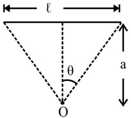
$~$
Perpendicular distance $(\mathrm{a})=\frac{\ell}{2} \cot \theta=\frac{\pi \mathrm{r}}{\mathrm{n}} \cot \theta$
$ \begin{aligned} \text{Mangetic field} ~ & \mathrm{B}=\mathrm{n} \times \frac{\mu _{0} \mathrm{i}}{4 \pi \mathrm{a}} 2 \sin \theta \\ & =\frac{\mu _{0} \mathrm{i}\left(2 \mathrm{n}^{2}\right) \sin \theta}{4 \pi(\pi \mathrm{r}) \cot \theta} \\ & =\frac{\mu _{0} \mathrm{i} \mathrm{n}^{2} \sin ^{2}(\pi / \mathrm{n})}{2 \pi^{2} \mathrm{r} \cos (\pi / \mathrm{n})} \end{aligned} $
Hence option (3) is correct
8. A regular hexagon, of side $h$, is carrying a current $i$ as shown, the magnetic field at the centre of hexagon is
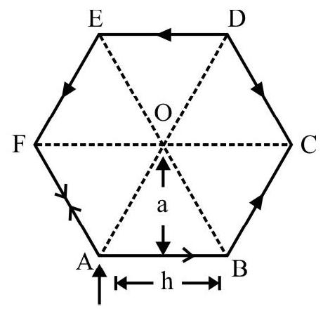
$~$
(1) $6\left[\frac{\mu _{0} \mathrm{i}}{\pi \mathrm{h}}\right)$
(2) $6\left[\frac{\mu _{0}}{4 \pi} \frac{\mathrm{i}^{2}}{\mathrm{~h}}\right)$
(3) $\frac{\mu _{0} 2}{2 \sqrt{3} \pi h}$
(4) $\sqrt{3}\left(\frac{\mu _{0} 2}{\pi \mathrm{h}}\right)$
Show Answer
Correct Answer: (4)
Solution:
The magnetic field (at the centre) due to all the six wires, forming a hexagon, are in the same direction, perpendicular tothe plan of page and directed outwards.
Due to a finite wire the magnetic field, at a point distant a from it, is
$$ \mathrm{B}=\frac{\mu _{0} 2}{4 \pi \mathrm{a}}\left[\frac{\ell _{1}}{\ell _{1}^{2}+\mathrm{a}^{2}}+\frac{\ell _{2}}{\sqrt{\ell _{2}^{2}+\mathrm{a}^{2}}}\right] $$
where $\ell _{1}$ and $\ell _{2}$ are the distances of the two ends of the wire, from the foot of perpendicular, drawn from the field point on the wire.
In the case of the hexagon we have
$$ \ell _{1}=\ell _{2}=\frac{\mathrm{h}}{2} \text { and } \mathrm{a}=\left(\frac{\mathrm{h}}{2}\right) \tan 60^{\circ}=\frac{\sqrt{3}}{2} \mathrm{~h} $$
The magnitude of the field, at 0 , due to each wire is
$$ B^{\prime}=\frac{\mu _{0} 2}{4 \pi\left(\frac{\sqrt{3}}{2} h\right)}\left[\frac{\frac{h}{2}}{\left(\frac{h}{2}\right)^{2}+\left(\frac{\sqrt{3} h}{2}\right)^{2}}+\frac{\frac{h}{2}}{\left(\frac{h}{2}\right)^{2}+\left(\frac{\sqrt{3} h}{2}\right)^{2}}\right]=\frac{\mu _{0} 2}{2 \sqrt{3} \pi h} $$
Hence the total field at centre of hexagon is $6 \mathrm{~B}$ '
or
$$ \mathrm{B}=6 \mathrm{~B}^{\prime}=\sqrt{3}\left[\frac{\mu _{0} 2}{\pi \mathrm{h}}\right] $$
Hence option(4) is correct
Difficult
Magnetic Field due to Long Straight Conductor
9. Two long parallel wires are at a distance $d$ apart. They carry stready equal currents flowing out of the plane of paper. The graph which would represent the variation of their magnetic field, along the line $\mathrm{XX}^{\prime}$; would be the graph labelled as graph
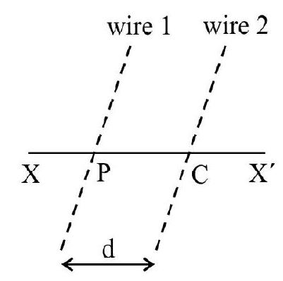
$~$
(1) $\mathrm{K}$
(2) L
(3) $\mathrm{M}$
(4) $\mathrm{N}$

$~$
Show Answer
Correct Answer: (2)
Solution:
If the current flow out of the paper, the magnetic field at points to the right of the wire, will be upwards and to the left will be downwards (in the plane of the peper).
Net magnetic field at point $\mathrm{O}$ :
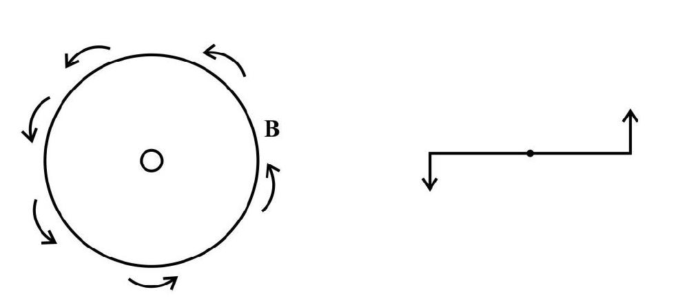
$~$
Magnetic field, in the region $\mathrm{QX}^{\prime}$ will be upward and positive, because all points, lying in this region, are to the right of both wires.

$~$
Magnetic field in the region $\mathrm{PC}$ will be upwards because points are closer to wire 1 compared to wire 2 . Similarly the magnetic field in the region CQ will be downwards. The variation of the magnetic field, due to a long straight wire, is as
$\frac{1}{\mathrm{r}}\left(\because \quad \mathrm{B}=\frac{\mu _{0} \mathrm{I}}{2 \pi \mathrm{r}} ; \mathrm{r}=\right.$ distance of field point. $)$
All these requirements are met by graph (L). Hence option (2) is the correct option.
Average
Magnetic Field due to Current Carrying Conductors
10. Two straight, infinitely long and thin parallel wires are spaced $0.1 \mathrm{~m}$ apart and carry a current of $10 \mathrm{ampere}$ each. The ratio of the magnetic fields, at a point at a distance of $0.1 \mathrm{~m}$ from both wires, for the two cases. When the currents are in (1) same direction and (ii) opposite directions; would be
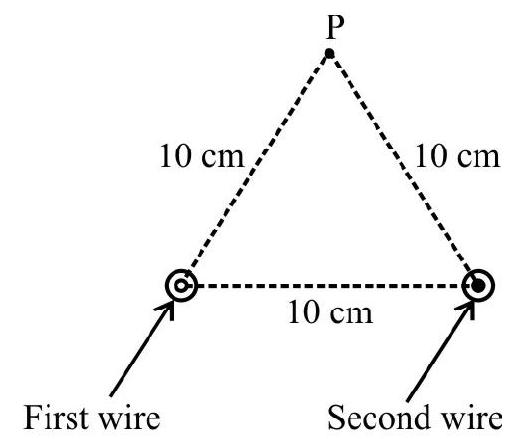
$~$
(1) $1: 1$
(2) $\sqrt{3}: 1$
(3) $1: \sqrt{3}$
(4) $\sqrt{2}: 1$
Show Answer
Correct Answer: (2)
Solution:
Since point ’ $P$ ’ is situated equidistant from the wires $A$ and $B$, hence magnitude of magnetic field at point $P$ due to both the wires will be same.
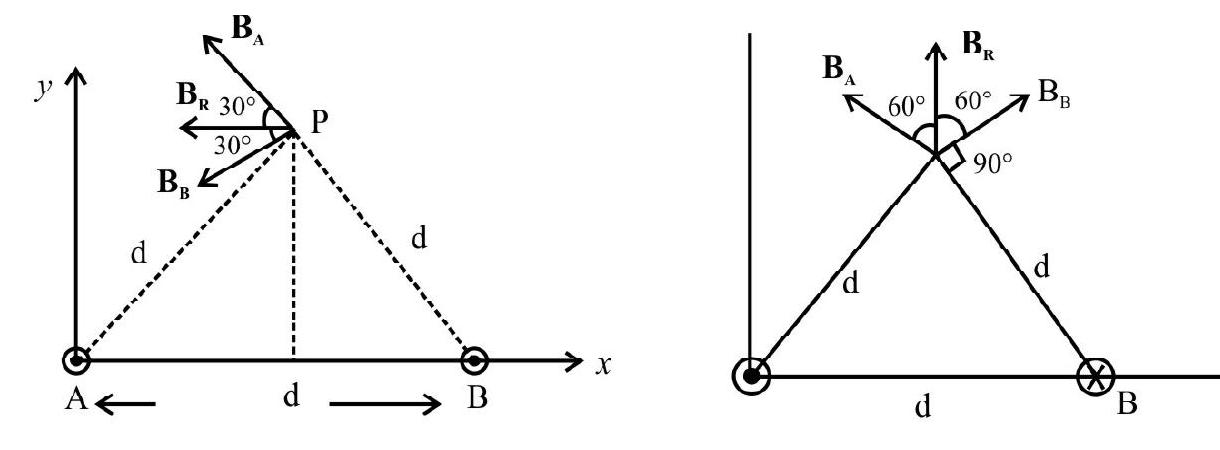
$~$
$ \mathrm{B}_{\mathrm{A}} =\mathrm{B} _{\mathrm{B}}=\mathrm{B}=\frac{\mu _0 \mathrm{i}}{2 \pi \mathrm{d}}=2 \times 10^{-7} \times \frac{10}{0.1}=2 \times 10^{-5} \mathrm{~T}$
(i) When wires carry currents in same direction (Fig. 1)
$\mathrm{B} _{\mathrm{R}}=2 \mathrm{~B} \cos \theta(-\hat{\mathrm{i}})=2 \sqrt{3} \times 10^{-5} \mathrm{~T}(-\hat{\mathrm{i}})$
(ii) When wires carry currents in opposite direction (Fig. 2)
$$ \mathrm{B} _{\mathrm{R}}=\cos \theta(+\hat{\mathrm{j}})=2 \mathrm{~B} \cos 60^{\circ}=2 \times 10^{-5} \mathrm{~T}(\text { along }+\hat{\mathrm{j}}) $$
Hence ratio of magnetic fields in two cases
$$ =\frac{\sqrt{3} \times 2 \times 10^{-5} \mathrm{~T}}{2 \times 10^{-5} \mathrm{~T}}=\sqrt{3}: 1 $$
Hence option(2) is correct
Average
Magnetic Field due to Moving Charged Particle
11. A pair of point charges $\mathrm{q} _{1}=+4 \mu \mathrm{C}$ and $\mathrm{q} _{2}=-1.5 \mu \mathrm{C}$ are moving in a frame of reference with the velocities $v _{1}$ and $\mathbf{v} _{2}$ $\left(\mathrm{v} _{1}=\mathbf{2} \times 10^{5} \mathrm{~m} / \mathrm{s}, \mathrm{v} _{2}=\mathbf{8} \times 10^{5} \mathrm{~m} / \mathrm{s}\right)$, as shown.The magnitude and direction of the magnetic field produced at the origin will be given by
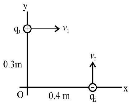
$~$
(1) $3.24 \times 10^{-6} \mathrm{~T}$ outwards
(2) $1.64 \times 10^{-6} \mathrm{~T}$ outwards
(3) $3.24 \times 10^{-6} \mathrm{~T}$ inwards
(4) $1.64 \times 10^{-6} \mathrm{~T}$ inwards
Show Answer
Correct Answer: (2)
Solution:
$\mathbf{B} _{1}=\frac{\mu _{0}}{4 \pi} \frac{\mathrm{q} _{1}\left(\mathbf{v} _{1} \times \mathbf{r} _{1}\right)}{\mathrm{r} _{1}^{3}}$
$ \begin{aligned} & =\frac{10^{-7} \times 4 \times 10^{-6}\left[2 \times 10^{5} \hat{\mathrm{i}} \times(+0.3 \hat{\mathrm{j}})\right]}{(0.3)^{3}} \mathrm{~T}=+\left(8.89 \times 10^{-7} \hat{\mathrm{k}}\right) \mathrm{T} \\ & \mathbf{B} _{2}=\frac{10^{-7} \times\left(-1.5 \times 10^{-6}\right)\left[8 \times 10^{5} \hat{\mathrm{j}} \times 0.4 \hat{\mathrm{i}}\right]}{(0.4)^{3}} \mathrm{~T}=\left[\left(7.5 \times 10^{-7}\right) \hat{\mathrm{k}}\right] \mathrm{T} \end{aligned} $
Total magnetic field $\mathbf{B}=\mathbf{B} _{1}+\mathbf{B} _{2}$
$$ \begin{aligned} & =\left[\left(8.89 \times 10^{-7}+7.5 \times 10^{-7}\right) \hat{\mathrm{k}}\right] \mathrm{T}=\left[16.4 \times 10^{-7}\right] \hat{\mathrm{k}} \mathrm{T} \\ & =1.64 \times 10^{-6} \mathrm{~T} \text { outwards } \end{aligned} $$
Hence option(2) is correct
Average
Biot-Savart Law
12. A circular coil, of radius a, carrying a current $I$, is located in the $x y$ plane, with its centre as the origin. The magnetic field $B$, due to this coil, at a general point $(0,0, c)$ on its axis, can be expressed as
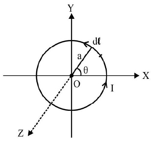
$~$
(1) $~~ \begin{aligned} \mathbf{B}=\frac{\mu _{0} \mathrm{I}}{4 \pi\left(\mathrm{a}^{2}+\mathrm{c}^{2}\right)^{3 / 2}}\left[\int _{0}^{2 \pi}(\mathrm{ad} \theta)(\hat{\mathrm{j}}-\hat{\mathrm{i}}) \times(\mathrm{a} \cos \theta \hat{\mathrm{i}}+\mathrm{a} \sin \theta \hat{\mathrm{j}}+\mathrm{c} \hat{\mathrm{k}})\right] \end{aligned} $
(2) $ ~~ \begin{aligned} \mathbf{B}=\frac{\mu _{0}}{4 \pi} I\left[\frac{\int _{0}^{2 \pi} \left(-a \sin \theta \hat{i}+a \cos \theta \hat{j} \right) \times \left(a \cos \theta \hat{i}+a \sin \theta \hat{j}+c \hat{k} \right)}{\left(a^{2}+c^{2}\right)}\right] \end{aligned} $
(3) $~~ \begin{aligned}\mathbf{B}=\frac{\mu _{0}}{4 \pi} I\left[\int _{0}^{2 \pi} \frac{(\mathrm{ad} \theta)(\hat{\mathrm{i}}-\hat{\mathrm{j}}) \times(\mathrm{a} \cos \theta \hat{\mathrm{i}}+\mathrm{a} \sin \theta \hat{\mathrm{j}}+\mathrm{c} \hat{\mathrm{k}})}{\left(\mathrm{a}^{2}+\mathrm{c}^{2}\right)}\right] \end{aligned}$
(4) $~~\begin{aligned}\mathbf{B}=\frac{\mu _{0} \mathrm{I}}{4 \pi}\left[\int _{0}^{2 \pi} \frac{(-\mathrm{a} \sin \theta \hat{\mathrm{i}}+\mathrm{a} \cos \theta \hat{\mathrm{j}}) \mathrm{d} \theta \times(-\mathrm{a} \cos \theta \hat{\mathrm{i}}-\mathrm{a} \sin \theta \hat{\mathrm{j}}+\mathrm{c} \hat{\mathrm{k}})}{\left(\mathrm{a}^{2}+\mathrm{c}^{2}\right)^{3 / 2}}\right] \end{aligned}$
Show Answer
Correct Answer: (4)
Solution:
We need to use the Biot-Savart law:
$$ \mathbf{B}=\frac{\mu _{0} \mathrm{I}}{4 \pi} \int \frac{\mathrm{d} \ell \times \mathbf{r}}{\mathrm{r}^{3}} $$
A current element, $\mathrm{d} \boldsymbol{\ell}$, of this circular coil, may be considered to be located around the point $(x, \mathrm{y})$. We have $\mathrm{d} \ell=\mathrm{d} x \hat{\mathrm{i}}+\mathrm{dy} \hat{\mathrm{j}}$
Now, as seen from the figure, $x=\mathrm{a} \cos \theta, \mathrm{y}=\mathrm{a} \sin \theta$
$\therefore \quad \mathrm{d} x=-\mathrm{a} \sin \theta \mathrm{d} \theta ; \quad \mathrm{dy}=\mathrm{a} \cos \theta \mathrm{d} \theta$
The vector $\mathbf{r}$, in the Biot-Savart law, is the position vector of the field point $(0,0, c)$ with respect to the location, $(x, y, 0)$, of the current element.
Hence $\mathbf{r}=(0-x) \hat{\mathrm{i}}+(0-\mathrm{y}) \hat{\mathrm{j}}+(\mathrm{c}-0) \hat{\mathrm{k}}$
$ =-a \cos \theta \hat{i}-a \sin \theta \hat{j}+c \hat{k} $
$\therefore|\mathrm{r}|=\left(\mathrm{a}^{2} \cos ^{2} \theta+\mathrm{a}^{2} \sin ^{2} \theta+\mathrm{c}^{2}\right)^{1 / 2}=\left(\mathrm{a}^{2}+\mathrm{c}^{2}\right)^{1 / 2}$
The variable $\theta$ varies from o to $2 \pi$. Hence
$$ \mathbf{B}=\frac{\mu _{0} I}{4 \pi\left(a^{2}+c^{2}\right)^{3 / 2}}\left[\int _{0}^{2 \pi}(-a \sin \theta \hat{\mathrm{i}}+\mathrm{a} \cos \theta \hat{\mathrm{j}}) \mathrm{d} \theta \times(-\mathrm{a} \cos \theta \hat{\mathrm{i}}-\mathrm{a} \sin \theta \hat{\mathrm{j}}+\mathrm{ck})\right] $$
Difficult
Magnetic Field due to a Circular Coil
13. We have two parallel co-axial circular coils of radius $R$, and number of turns $N$, carrying equal currents in the same direction. The two coils are separated by a distance $R$. The magnetic field, on their axis, around the midpoint between the coils, is (nearly)
(1) $\frac{\mu _{0} i R^{2} \mathrm{~N}}{2}$
(2) $0.36 \frac{\mu _{0} \mathrm{Ni}}{\mathrm{R}}$
(3) $0.08 \frac{\mu _{0} \mathrm{Ni}}{\mathrm{R}}$
(4) $0.72 \frac{\mu _{0} \mathrm{Ni}}{\mathrm{R}}$
Show Answer
Correct Answer: (4)
Solution:
We know that the magnetic field, due to a circular coil, at an axial point distance $z$ from its centre is given by
$$ B=\frac{\mu _{0} i R^{2} N}{2\left(z^{2}+R^{2}\right)^{3 / 2}} $$
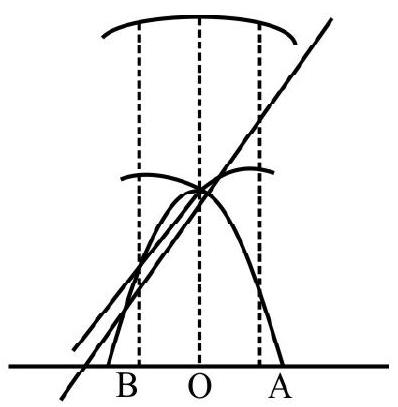
$~$
The field, due to first coil, at a point on its axis, at a distance of $\frac{\mathrm{R}}{2}$ from the centre, is
$$ \begin{aligned} \mathrm{B} _{1}= & \frac{\mu _{0} \mathrm{i} \mathrm{NR}^{2}}{2\left(\frac{\mathrm{R}^{2}}{4}+\mathrm{R}^{2}\right)^{3 / 2}}=\frac{\mu _{0} \mathrm{Ni}}{2\left(\frac{5}{4}\right)^{3 / 2} \mathrm{R}^{3}} \\ & \cong \frac{\mu _{0} \mathrm{Ni}}{2 \mathrm{R} \times 1.4} \equiv \frac{\mu _{0} \mathrm{Ni}}{2.8 \mathrm{R}}=\frac{0.36 \mu _{0} \mathrm{Ni}}{\mathrm{R}} \end{aligned} $$
Similarly the field, due to the second coil at a point on its axis, at a distance $\left(\frac{\mathrm{R}}{2}\right)$ from its centre is, given by $\mathrm{B} _{2}=\frac{0.36 \mu _{0} \mathrm{Ni}}{\mathrm{R}}$
Resultant field $\mathbf{B}=\mathbf{B} _{1}+\mathbf{B} _{2}$
The two fields, being in the same direction, we have
$\therefore|\mathbf{B}| \cong 0.72 \frac{\mu _{0} \mathrm{Ni}}{\mathrm{R}}$
Hence option(4) is correct
Average
Magnetic Field due to Straight and Circular Coils
14. Figure shows a semi circular coil of radius $z$ along with long straight wires. When a current I flows through this set up, the magnetic field, at $O$, the centre of semi circular arc, equals
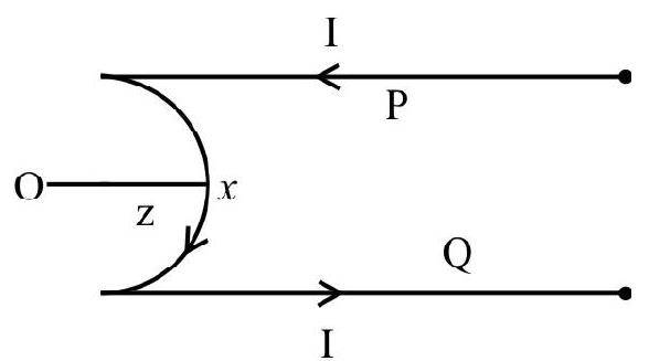
$~$
(1) $\frac{\mu _{0} \mathrm{i}}{4 \pi \mathrm{z}}\left(\frac{\pi}{2}-2\right)$ outwards
(2) $\frac{\mu _{0} \mathrm{i}}{4 \pi \mathrm{z}}(\pi+2)$ outwards
(3) $\frac{\mu _{0} \mathrm{i}}{4 \pi z}(\pi-2)$ into the plane of the paper
(4) $\frac{\mu _{0} \mathrm{i}}{4 \pi z}\left(\frac{\pi}{2}+2\right)$ into the plane of the paper
Show Answer
Correct Answer: (3)
Solution:
Magnetic field, due to semi circular portion, is given by
$\mathrm{B} _{1}=\frac{1}{2} \frac{\mu _{0}}{4 \pi} \frac{(2 \pi \mathrm{i})}{\mathrm{z}}=\frac{\mu _{0} \pi \mathrm{i}}{4 \pi \mathrm{z}}$ directed inwards
Now the the point $\mathrm{O}$ is at a distance $\mathrm{z}$ from the straight conductor $\mathrm{P}$ of infinite length.
$\therefore\left|\mathbf{B} _{2}\right|=\frac{\mu _{0} \mathrm{i}}{4 \pi \mathrm{z}}$ directed outward
Also, the magnetic field at point $\mathrm{O}$ due to infinite long straight conductor $\mathrm{Q}$, is given by
$\mathbf{B} _{3}=\frac{\mu _{0} \mathrm{i}}{4 \pi \mathrm{z}}$ directed outward
Hence the resultant field
$ \mathrm{B}=\mathrm{B} _{1}-\mathrm{B} _{2}-\mathrm{B} _{3} $
or $\quad B=\frac{\mu _{0} \pi i}{4 \pi z}-\frac{\mu _{0} i}{4 \pi z}-\frac{\mu _{0} i}{4 \pi z}=\frac{\mu _{0} i}{4 \pi z}(\pi-2)$, into the plane of the paper.
Hence option (3) is correct
Average
15. The graph which represents the variation of magnetic field, $|\mathrm{B}|$, at axial points for a circular coil, with distance, $x$ from the centre of the circular coil, is the graph labelled as graph
(1) $\mathrm{K}$
(2) $\mathrm{L}$
(3) $\mathrm{M}$
(4) $\mathrm{N}$
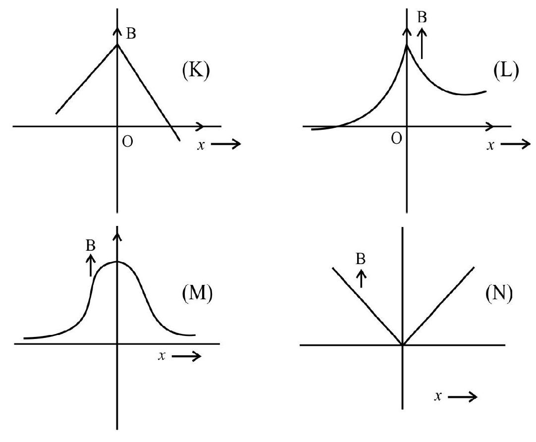
$~$
Show Answer
Correct Answer: (3)
Solution:
The field due to a circular coil, of radius a, at an axial point distance $x$ from centre, is given by
$$ |\mathbf{B}|=\frac{\mu _{0} \mathrm{ni}}{2} \frac{\mathrm{a}^{2}}{\left(\mathrm{a}^{2}+x^{2}\right)^{3 / 2}} $$
From above relation it is clear that $|\mathbf{B}|$ will have maximum value at the centre $\mathrm{O}(x=0)$. From this value it decreases symmetrically along both the positive and negative $x$-axis. Hence option (3) is the correct option.
Average
Magnetic Field due to Current Loop
16. The figure shows a wire frame, in $x y$ plane, carrying a current $I$, the magnetic field at point ’ $\mathrm{O}$ ’ is
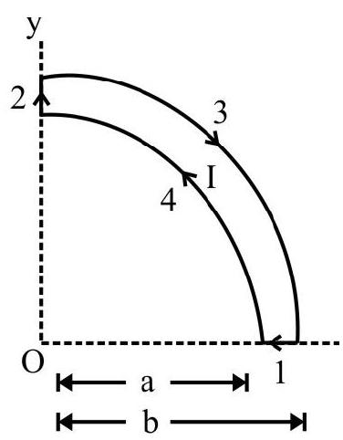 $~$
$~$
(1) $\frac{\mu _{0} \mathrm{I}}{8}\left[\frac{1}{\mathrm{a}}-\frac{1}{\mathrm{~b}}\right] \hat{\mathrm{k}}$
(2) $\frac{\mu _{0} \mathrm{I}}{8}\left[\frac{1}{\mathrm{~b}}+\frac{1}{\mathrm{a}}\right] \hat{\mathrm{k}}$
(3) $\frac{\mu _{0} \mathrm{I}}{4}\left[\frac{1}{\mathrm{a}}-\frac{1}{\mathrm{~b}}\right] \hat{\mathrm{k}}$
(4) $\frac{\mu _{0} \mathrm{I}}{4}\left[\frac{1}{\mathrm{~b}}+\frac{1}{\mathrm{a}}\right] \hat{\mathrm{k}}$
Show Answer
Correct Answer: (1)
Solution:
Magnetic field at point $\mathrm{O}$
$ \mathbf{B} _{0}=\mathbf{B} _{1}+\mathbf{B} _{2}+\mathbf{B} _{3}+\mathbf{B} _{4} $
$\mathbf{B} _{1}=0=\mathbf{B} _{2}$
$\mathbf{B} _{4}=\frac{\mu _{0} \mathrm{I}}{8 \mathrm{a}} \hat{\mathrm{k}}$
$\mathbf{B} _{3}=\frac{\mu _{0} \mathrm{I}}{8 \mathrm{~b}}(-\hat{\mathrm{k}})$
$\Rightarrow \mathrm{B} _{0}=\frac{\mu _{0} \mathrm{I}}{8 \mathrm{a}} \hat{\mathrm{k}}-\frac{\mu _{0} \mathrm{I}}{8 \mathrm{~b}} \hat{\mathrm{k}}$
Thus $\mathrm{B} _{0}=\frac{\mu _{0} \mathrm{I}}{8}\left[\frac{1}{\mathrm{a}}-\frac{1}{\mathrm{~b}}\right] \hat{\mathrm{k}}$
Hence option(1) is correct
Difficult
Magnetic Field on the Axis of a Circular Loop
17. The figure shows two coaxial circular loops 1 and 2 , which form the same angle $\theta$ at point ’ $O$ ‘. If $B _{1}$ and $B _{2}$ are the magnetic fields produced at the point ’ $O$ ‘, due to loops 1 and 2 , respectively. Then
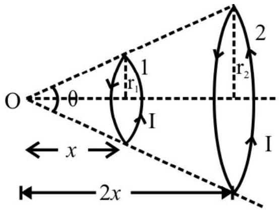
$~$
(1) $\frac{\mathrm{B} _{1}}{\mathrm{~B} _{2}}=1$
(2) $\frac{\mathrm{B} _{1}}{\mathrm{~B} _{2}}=2$
(3) $\frac{\mathrm{B} _{1}}{\mathrm{~B} _{2}}=4$
(4) $\frac{\mathrm{B} _{1}}{\mathrm{~B} _{2}}=8$
Show Answer
Correct Answer: (2)
Solution:
$ \mathrm{B} _{1}=\frac{\mu _{0} \mathrm{IA} _{1}}{2\left(x _{1}^{2}+\mathrm{r} _{1}^{2}\right)^{3 / 2}}=\frac{\mu _{0} 2 \mathrm{I} \pi \mathrm{r} _{1}^{2}}{4 \pi\left(x _{1}^{2}+\mathrm{r} _{1}^{2}\right)^{3 / 2}} $
Similarly $\mathrm{B} _{2}=\frac{\mu _{0} 2 \mathrm{I} \pi \mathrm{r} _{1}^{2}}{4 \pi\left(x _{2}^{2}+\mathrm{r} _{2}^{2}\right)^{3 / 2}}$
$ \frac{\mathrm{B} _{1}}{\mathrm{~B} _{2}}=\frac{\mathrm{r} _{1}^{2}\left(x _{2}^{2}+\mathrm{r} _{2}^{2}\right)^{3 / 2}}{\mathrm{r} _{2}^{2}\left(x _{1}^{2}+\mathrm{r} _{1}^{2}\right)^{3 / 2}} $
But $\quad \mathrm{r} _{1}=x \tan \theta / 2 \quad$ and $ \quad x _{1}=x$
$ \quad \quad \mathrm{r} _{2}=2 x \tan \theta / 2 \quad \text { and } \quad x _{2}=2 x $
$\therefore \quad \frac{\mathrm{B} _{1}}{\mathrm{~B} _{2}}=\frac{x^{2} \tan ^{2} \theta / 2\left(4 x^{2}+4 x^{2} \tan ^{2} \theta / 2\right)^{3 / 2}}{4 x^{2} \tan ^{2} \theta / 2\left(x^{2}+x^{2} \tan ^{2} \theta / 2\right)^{3 / 2}}$
$=\frac{1}{4} \times \frac{(4)^{3 / 2}\left(1+\tan ^{2} \theta / 2\right)^{3 / 2}}{\left(1+\tan ^{2} \theta / 2\right)^{3 / 2}}=2$
Hence option(2) is correct
18. Current I flows through the wire as shown in figure, the semicircular part of the wire is perpendicular to $x-y$ plane and out of the plane of paper. The mangetic field, at the centre ’ $C$ ‘, of the semi circle, would be
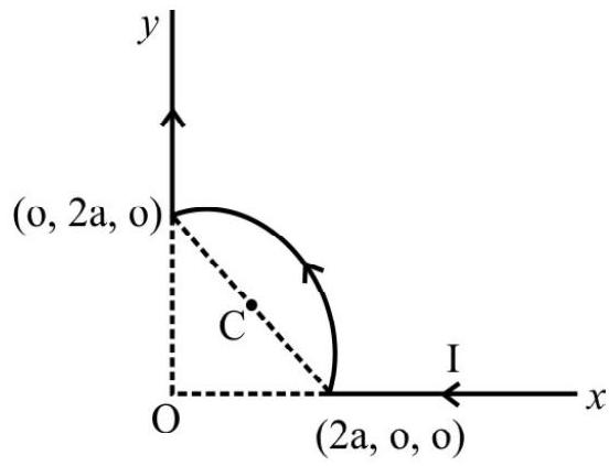
$~$
(1) $\frac{-\mu _{0} I}{4 \mathrm{a}}\left[\frac{\hat{\mathrm{i}}+\hat{\mathrm{j}}}{2}+\frac{(2-\sqrt{2})}{\pi} \hat{\mathrm{k}}\right]$
(2) $\frac{-\mu _{0} I}{4 \pi \mathrm{a}}\left[\frac{\hat{\mathrm{i}}+\hat{\mathrm{j}}}{2 \pi}+\frac{(2-\sqrt{2})}{1} \hat{\mathrm{k}}\right]$
(3) $\frac{+\mu _{0} I}{4 a}\left[\frac{\hat{i}+\hat{j}}{2}+\frac{(2-\sqrt{2})}{\pi} \hat{\mathrm{k}}\right]$
(4) $\frac{-\mu _{0} \mathrm{I}}{4 \mathrm{a}}\left[\frac{\hat{\mathrm{i}}-\hat{\mathrm{j}}}{2}+\frac{(2-\sqrt{2})}{\pi}(-\hat{\mathrm{k}})\right]$
Show Answer
Correct Answer: (1)
Solution:
Magnitude of magnetic field at point ’ $C$ ’ due to straight conductor.
$ \begin{aligned} \left|\mathbf{B} _{1}\right| & =\frac{-\mu _{0} \mathrm{I}}{4 \pi \mathrm{a}}\left[\sin 90^{0}-\sin 45^{0}\right]=\frac{\mu _{0} \mathrm{I}}{4 \pi \mathrm{a}}\left(1-\frac{1}{\sqrt{2}}\right) \\ & =\frac{-\mu _{0} \mathrm{I}}{4 \pi \mathrm{a}}\left[\frac{\sqrt{2}-1}{\sqrt{2}}\right] \text { along }(-\mathrm{z}) \text { direction } \end{aligned} $
Magnetic field due to semicircular part
$ \mathrm{B} _{2}=\frac{\mu _{0} \mathrm{I}}{4 \sqrt{2} \mathrm{a}} \text { along } \mathrm{CO} $
(Radius of semicircle $=\frac{2 \sqrt{2} \mathrm{a}}{2}=\sqrt{2} \mathrm{a}$ ) and Unit vector along $\mathrm{CO}=-\frac{1}{\sqrt{2}}(\hat{\mathrm{i}}+\hat{\mathrm{j}})$
$\therefore$ Resultant magnetic field at $\mathrm{C}$
$ \mathbf{B}=2 \frac{\mu _{0} \mathrm{I}}{4 \pi \mathrm{a}}\left(\frac{1}{\sqrt{2}}-1\right) \hat{\mathrm{k}}-\frac{\mu _{0} \mathrm{I}}{4 \mathrm{a}} \frac{(\hat{\mathrm{i}}+\hat{\mathrm{j}})}{2}=\frac{-\mu _{0} \mathrm{I}}{4 \mathrm{a}}\left[\frac{\hat{\mathrm{i}}+\hat{\mathrm{j}}}{2}+\frac{(2-\sqrt{2})}{\pi} \hat{\mathrm{k}}\right] $
Hence option(1) is correct
Average
Magnetic Field on the Axis of Current Carrying Loop
19. A uniformly charged ring, (having a charge q), of radius $R$, is rotated about its axis with constant linear speed $v$ for each of its particles. The ratio of the electric to magnetic field, at a point $P$, on the axis of the ring, distance $x=R$ from the centre of the ring, is (’ $c$ ’ is the speed of light)
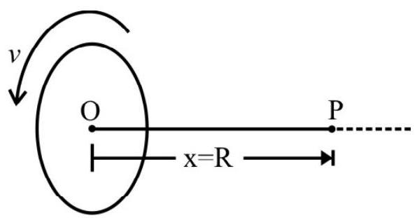
$~$
(1) $\frac{\mathrm{c}^{2}}{\mathrm{v}}$
(2) $\frac{v^{2}}{\mathrm{c}}$
(3) $\frac{\mathrm{v}}{\mathrm{c}}$
(4) $\frac{\mathrm{c}}{\mathrm{v}}$
Show Answer
Correct Answer: (1)
Solution:
At point $\mathrm{P}$
$ \begin{aligned} & \mathrm{E}=\frac{1}{4 \pi \varepsilon _{0}} \frac{\mathrm{q} x}{\left(\mathrm{R}^{2}+x^{2}\right)^{3 / 2}}=\frac{1}{4 \pi \varepsilon _{0}} \frac{\mathrm{qR}}{\left(\mathrm{R}^{2}+x^{2}\right)^{3 / 2}} \\ & \mathrm{~B}=\frac{\mu _{0}}{4 \pi} \frac{2 \mathrm{iA}}{\left(\mathrm{R}^{2}+x^{2}\right)^{3 / 2}} \end{aligned} $
Here $\mathrm{i}=\frac{\mathrm{q}}{\mathrm{T}}=\frac{\mathrm{qv}}{2 \pi \mathrm{R}}$ and Area $\mathrm{A}=\pi \mathrm{R}^{2}$
$\therefore \quad \mathrm{B}=\frac{\mu _{0}}{4 \pi} \frac{\mathrm{qvR}}{\left(\mathrm{R}^{2}+x^{2}\right)^{3 / 2}}$
$\therefore \frac{\mathrm{E}}{\mathrm{B}}=\frac{1}{\mu _{0} \varepsilon _{0}} \cdot \frac{1}{\mathrm{v}} \Rightarrow \frac{\mathrm{c}^{2}}{\mathrm{v}} \quad\left(\because \mathrm{C}=\frac{1}{\sqrt{\mu _{0} \varepsilon _{0}}}\right)$
Hence option (1) is correct
Average
Magnetic Field due to Current Carrying Circular Loop
20. In the given figure, the magnetic field at point $P$ is
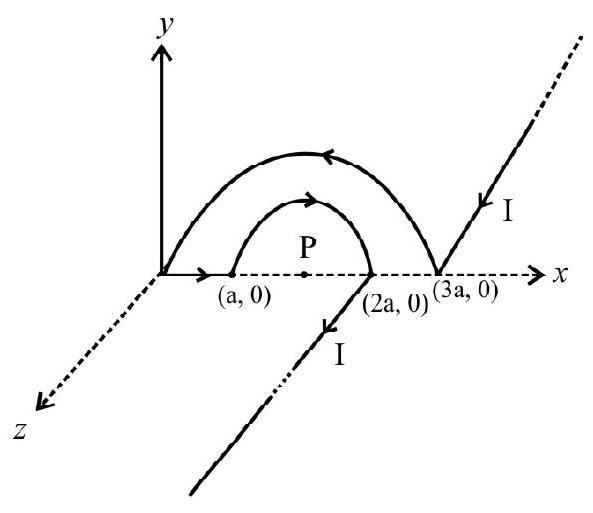
$~$
(1) $\frac{2 \mu _{0} \mathrm{I}}{3 \pi \mathrm{a}} \sqrt{4-\pi^{2}}$
(2) $\frac{\mu _{0} \mathrm{I}}{3 \pi \mathrm{a}} \sqrt{4+\pi^{2}}$
(3) $\frac{2 \mu _{0} \mathrm{I}}{3 \pi \mathrm{a}}\left(4+\pi^{2}\right)$
(4) $\frac{2 \mu _{0} \mathrm{I}}{3 \pi \mathrm{a}}\left(4-\pi^{2}\right)$
Show Answer
Correct Answer: (2)
Solution:
Total magnetic field at point $\mathrm{P}$
$\mathbf{B} _{\mathrm{P}}=\left(\mathbf{B} _{1}\right) _{\mathrm{P}}+\left(\mathbf{B} _{2}\right) _{\mathrm{P}}+\left(\mathbf{B} _{3}\right) _{\mathrm{P}}+\left(\mathbf{B} _{4}\right) _{\mathrm{P}}+\left(\mathbf{B} _{5}\right) _{\mathrm{P}} $
$\left(\mathbf{B} _{1}\right) _{\mathrm{P}}=\frac{\mu _{0} \mathrm{I}}{4 \pi\left(\frac{3 \mathrm{a}}{2}\right)}(-\hat{\mathrm{j}}) \text { semi infinite wire }$
$\left(\mathbf{B} _{2}\right) _{\mathrm{P}}=\frac{\mu _{0} \mathrm{I}}{4\left(\frac{3 \mathrm{a}}{2}\right)}(+\hat{\mathrm{k}})$
$\left(\mathbf{B} _{3}\right) _{\mathrm{P}}=0$ ( $\mathrm{P}$ is along the wire)
$\left(\mathbf{B} _{4}\right) _{\mathrm{P}}=\frac{\mu _{0} \mathrm{I}}{4\left(\frac{\mathrm{a}}{2}\right)}(-\hat{\mathrm{k}}) _{\text {semi inifinte wire }}$
$\left(\mathbf{B} _{5}\right) _{\mathrm{P}}=\frac{\mu _{0} \mathrm{I}}{4 \pi\left(\frac{\mathrm{a}}{2}\right)}(-\hat{\mathrm{j}})$
$\mathbf{B} _{P}=-\frac{2 \mu _{0} \mathrm{I}}{3 \mathrm{a}}\left[\frac{2}{\pi} \hat{\mathrm{j}}+\hat{\mathrm{k}}\right] \quad \frac{\mu _{0} \mathrm{I}}{3 \pi \mathrm{a}} \sqrt{4+\pi^{2}}$
Hence option(2) is correct
Average/Easy
Magnetic Field on the Axis of a Current Carrying Circular Loop
21. A current carrying circular loop, of radius a, produces a magnetic field. The variation of the axial magnetic field with distance (on the axis) from centre, will be depicted by the graph, labelled as graph.
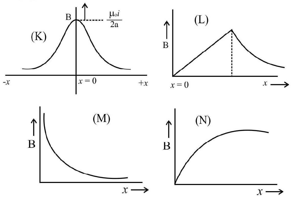
$~$
(1) $\mathrm{K}$
(2) $\mathrm{L}$
(3) $\mathrm{M}$
(4) $\mathrm{N}$
Show Answer
Correct Answer: (1)
Solution:
$\mathrm{B}$, on the axis, at distance $x$, is given by
$$ \mathrm{B}=\frac{\mu _{0} \mathrm{ia}^{2}}{2\left(\mathrm{a}^{2}+x^{2}\right)^{3 / 2}} $$
This shows that $\mathrm{B}$ decreases, in a (non-linear) symmetrical way, from its maximum value (at $x=0$ ). It is graph $(\mathrm{K})$ that is in accordance with these requirements.
Hence option(1) is correct
Difficult
Magnetic Field on the Axis of Current Carrying Circular Coil
22. A charge of one coulomb is placed at one end of a non conducting rod of length $0.6 \mathrm{~m}$. The rod is rotated in a vertical plane about a horizontal axis (passing through the other end of the rod) with an angular frequency $\pi \times 10^{6} \mathrm{radian} / \mathrm{second}$.
If half of the charge be removed from one end and placed on the other end, the rod is again rotated in a vertical plane, but now about the horizontal axis passing through the mid point of the rod, (with the same angular frequency).
The ratio of the magnetic field, in the two cases, at a point on the axis [whose distance from the centre, in first case, is $0.8 \mathrm{~m}$ and in second case $0.4 \mathrm{~m}]$, would be
(1) $1: 1$
(2) $2: 1$
(3) $1: 2$
(4) $2: 3$
Show Answer
Solution:
Revolving charge is equivalent to current $\mathrm{I}=\mathrm{qv}$, the field, at a distance ’ $\mathrm{d}$ ‘, from centre, on the axis of a current carrying circular coil, is
$B=\frac{\mu _{0} \mathrm{ia}^{2}}{2\left(\mathrm{a}^{2}+\mathrm{d}^{2}\right)^{3 / 2}}$ where ’ $\mathrm{a}$ ’ is the radius of the coil.
In first case we have $\mathrm{I}=\frac{\mathrm{q} \omega}{2 \pi}=5 \times 10^{3} \mathrm{~A}$
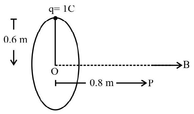
$~$
$ \therefore \mathrm{B}=\frac{4 \pi \times 10^{-7} \times 5 \times 10^{3} \times(0.6)^{2}}{2\left[(0.6)^{2}+(0.8)^{2}\right]^{3 / 2}}=1.13 \times 10^{-3} \mathrm{~T} $
In the second case we have the equivalent current, for each half,
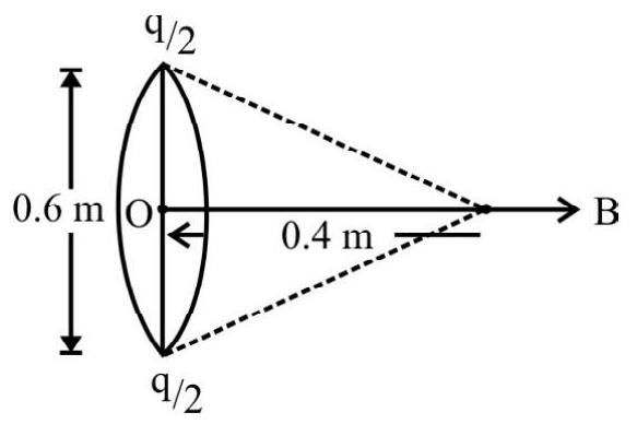
$~$
$ \mathrm{I}^{\prime}=\frac{\mathrm{qv}}{2}=\frac{5}{2} \times 10^{+3} \mathrm{~A} $
Here $\mathrm{a}=0.3 \mathrm{~m}, \mathrm{~d}=0.4 \mathrm{~m}$
$ \mathrm{B}^{\prime}=2 \times\left[\frac{4 \pi \times 10^{-7} \times \frac{5}{2} \times 10^{3} \times(0.3)^{2}}{2\left[(0.3)^{2}+(0.4)^{2}\right]^{3 / 2}}\right] $
$\therefore$ Ratio of magnetic field, produced in first case, to that in the second case, is
$ \begin{aligned} \frac{\mathrm{B}}{\mathrm{B}^{\prime}} & =\left(\frac{0.6}{0.3}\right)^{2} \times \frac{\left[(0.3)^{2}+(0.4)^{2}\right]^{3 / 2}}{\left[(0.6)^{2}+(0.8)^{2}\right]^{3 / 2}}=4 \times \frac{25 \times 5}{100 \times 10}=\frac{1}{2} \\ \\ & =1: 2 \end{aligned} $
Hence option(3) is correct
Average
Magnetic Field due to a Current Loop
23. Consider a co-axial cable which consists of an inner wire of radius ’ $a$ ‘, surrounded by an outer shell, of inner and outer radii $b$ and $c$, respectively. The inner wire carries a current I and the outer shell carries an equal and opposite current. The magnetic field at a distance $x$ from the axis, where $b<x<c$, is
(1) $\frac{\mu _{0} \mathrm{I}\left(\mathrm{c}^{2}-\mathrm{b}^{2}\right)}{2 \pi x\left(\mathrm{c}^{2}-\mathrm{a}^{2}\right)}$
(2) $\frac{\mu _{0} \mathrm{I}\left(\mathrm{c}^{2}-x^{2}\right)}{2 \pi x\left(\mathrm{c}^{2}-\mathrm{a}^{2}\right)}$
(3) $\frac{\mu _{0} \mathrm{I}\left(\mathrm{c}^{2}-x^{2}\right)}{2 \pi x\left(\mathrm{c}^{2}-\mathrm{b}^{2}\right)}$
(4) $\frac{\mu _{0} \mathrm{I}\left(\mathrm{c}^{2}-\mathrm{b}^{2}\right)}{2 \pi x\left(\mathrm{c}^{2}-x^{2}\right)}$
Show Answer
Correct Answer: (3)
Solution:
Consider an amperian loop of radius ’ $x$ ’ $(\mathrm{b}<x<\mathrm{c})$ Threaded current I’, by this amperian loop, is
$\mathrm{I}^{\prime}=\mathrm{I}+\left(\frac{x^{2}-\mathrm{b}^{2}}{\mathrm{c}^{2}-\mathrm{b}^{2}}\right)(-\mathrm{I})=\left(\frac{\mathrm{c}^{2}-x^{2}}{\mathrm{c}^{2}-\mathrm{b}^{2}}\right) \mathrm{I}$
$\therefore \quad \mathrm{B}=\frac{\mu _{0} \mathrm{I}^{\prime}}{2 \pi x}=\frac{\mu _{0} \mathrm{I}\left(\mathrm{c}^{2}-x^{2}\right)}{2 \pi x\left(\mathrm{c}^{2}-\mathrm{b}^{2}\right)}$
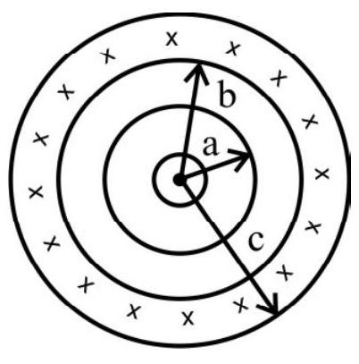
$~$
Hence option (3) is correct
Difficult
Magnetic Field due to Cylindrical Conductor Carrying Current
24. Along cylindrical conductor, of radius ’ $a$ ‘, has two cylindrical cavities of diameter ’ $a$ ‘, through its entire length, as shown in cross section in figure. A current $I$ is directed out of the page and is uniform throughout the cross section of the conductor; the magnitude and direction of magnetic field at point $P$ will be
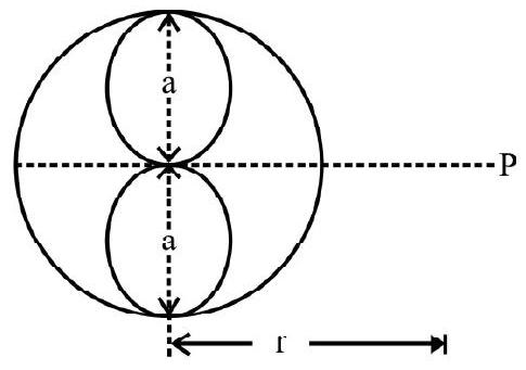
$~$
(1) $\frac{\mu_0 \mathrm{I}}{\pi \mathrm{r}}\left[\frac{2 \mathrm{r}^2+\mathrm{a}^2}{4 \mathrm{r}^2+\mathrm{a}^2}\right]$ upwards
(2) $\frac{\mu _{0} I}{2 \pi r}\left[\frac{2 r^{2}+a^{2}}{4 r^{2}+a^{2}}\right]$ upwards
(3) $\frac{\mu _{0} \mathrm{I}}{\pi \mathrm{r}}\left[\frac{2 \mathrm{r}^{2}+\mathrm{a}^{2}}{4 \mathrm{r}^{2}+\mathrm{a}^{2}}\right]$ downwards
(4) $\frac{\mu _{0} \mathrm{I}}{2 \pi \mathrm{r}}\left[\frac{2 \mathrm{r}^{2}+\mathrm{a}^{2}}{4 \mathrm{r}^{2}+\mathrm{a}^{2}}\right]$ downwards
Show Answer
Correct Answer: (1)
Solution:
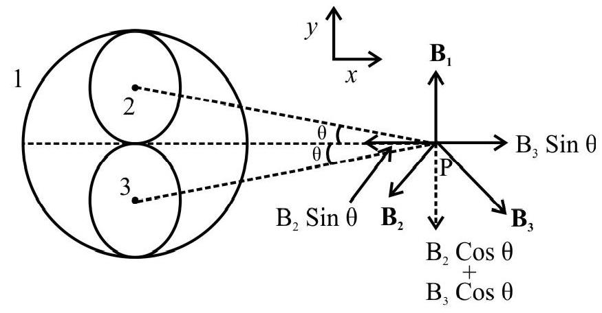
$~$
Let $\mathrm{B} _{1}, \mathrm{~B} _{2}$ and $\mathrm{B} _{3}$ be the magnetic fields, due to complete cylinder and due to the upper and lower cavity respectivley.
$$ \begin{aligned} & \mathbf{B} _{1}=\frac{\mu _{0}}{4 \pi} \frac{2 I _{1}}{r} \hat{j}=\frac{\mu _{0} I}{\pi r} \hat{j} \\ & \mathbf{B} _{2}=\frac{\mu _{0}}{4 \pi} \frac{2 I _{2}}{\sqrt{r^{2}+\frac{a^{2}}{4}}}[-\sin \theta \hat{i}-\cos \theta \hat{j}]=\frac{-\mu _{0} I}{2 \pi \sqrt{4 r^{2}+a^{2}}}(+\sin \theta \hat{i}+\cos \theta \hat{j}) \\ & \mathbf{B} _{3}=\frac{\mu _{0}}{4 \pi} \frac{2 I _{3}}{\sqrt{r^{2}+\frac{a^{2}}{4}}}(\sin \theta \hat{i}-\cos \theta \hat{j})=\frac{\mu _{0} I}{2 \pi \sqrt{4 r^{2}+a^{2}}}(\sin \theta \hat{i}-\cos \theta \hat{j}) \end{aligned} $$
Total $\mathbf{B}=\mathbf{B} _{1}+\mathbf{B} _{2}+\mathbf{B} _{3}=\frac{\mu _{0} \mathrm{I}}{2 \pi}\left[\frac{2}{\mathrm{r}}-\frac{2 \cos \theta}{\sqrt{4 \mathrm{r}^{2}+\mathrm{a}^{2}}}\right] \hat{\mathrm{j}}$
$ \begin{aligned} & \text { But } \cos \theta=\frac{r}{\sqrt{r^{2}+\frac{a^{2}}{4}}}=\frac{2 r}{\sqrt{4 r^{2}+a^{2}}} \\ & \begin{aligned} & B= \frac{\mu _{0} I}{2 \pi}\left[\frac{2}{r}-\frac{4 r}{\left(4 r^{2}+a^{2}\right)}\right] \hat{j}=\frac{\mu _{0} I}{2 \pi r}\left[2-\frac{4 r^{2}}{4 r^{2}+a^{2}}\right] \hat{j} \\ &= \frac{\mu _{0} I}{2 \pi r}\left[\frac{8 r^{2}+2 a^{2}-4 r^{2}}{4 r^{2}+a^{2}}\right] \hat{j}=\frac{2 \times \mu _{0} I}{2 \pi r}\left[\frac{2 r^{2}+a^{2}}{4 r^{2}+a^{2}}\right] \hat{j} \\ & \quad=\frac{\mu _{0} I}{\pi r}\left[\frac{2 r^{2}+a^{2}}{4 r^{2}+a^{2}}\right] \hat{j} \end{aligned} \end{aligned} $
Hence option(1) is correct
Average
Ampere’s Circuital Law
25. The current density, in a wire of radius ’ $a$ ‘, varies with ’ $r$ ’ according to $\mathbf{j}=\mathbf{K r}^{2}$, where $\mathrm{K}$ is a constant and ’ $r$ ’ is the distance from the axis of the wire, the magnitude of magnetic field at a point (inside the wire), at distance ’ $r$ ’ $(0<r<a)$ from the axis, will be
(1) $\frac{\mu _{0} \mathrm{Ka}^{4}}{4 \mathrm{r}}$
(2) $\frac{\mu _{0} \mathrm{Kr}^{2}}{4}$
(3) $\frac{\mu _{0} \mathrm{Kr}^{3}}{4}$
(4) zero
Show Answer
Correct Answer: (3)
Solution:
Current passing through the area enclosed by (the Amperian) path
$\mathrm{dI}=\mathrm{jdA}=\operatorname{Kr}^{2}(2 \pi \mathrm{rdr})$
$ \mathrm{I}=\mathrm{K} \int _{0}^{\mathrm{r}} 2 \pi \mathrm{r}^{3} \mathrm{dr}=\frac{\pi \mathrm{Kr} \mathrm{r}^{4}}{2} $
Using Ampere’s circuital law
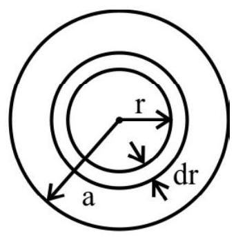
$~$
$ \oint \mathbf{B} \cdot \mathrm{d} \ell=\mu _{0} \mathrm{i} _{\text {enclosed }} $
$ \begin{aligned} & \mathrm{B} \times 2 \pi \mathrm{r}=\frac{\mu _{0} \mathrm{~K} \pi \mathrm{r}^{4}}{2} \\ & \mathrm{~B}=\frac{\mu _{0} \mathrm{Kr}^{3}}{4} \end{aligned} $
Hence option(3) is correct
Difficult
Ampere’s Circuital Law
26. Two infinite plates, shown in cross section in figure, carry $i$ amperes of current and out of page per unit width of the plates. The magnetic field, at points $P$ and $Q$, will be, respectively,
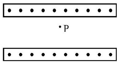
$~$
(1) 0 and $\mu _{0} \mathrm{i}$
(2) 0 and $\frac{1}{2} \mu _{0} \mathrm{i}$
(3) $\frac{1}{2} \mu _{0} \mathrm{i}$ and $\mu _{0} \mathrm{i}$
(4) $\mu _{0} \mathrm{i}$ and 0
Show Answer
Correct Answer: (1)
Solution:
To calculate the magnetic field due to current carrying infinite plate at point A.
Choose PQRS as an Amperian loop.
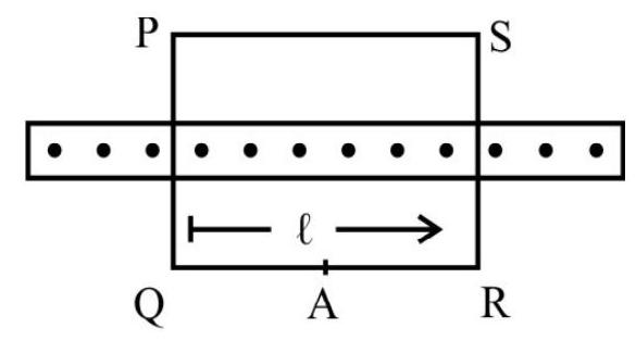
$~$
$ \begin{aligned} & \oint _{P Q R S} \mathbf{B} \cdot \mathrm{d} \ell=\int _{\mathrm{P} \rightarrow \mathrm{Q}} \mathbf{B} \cdot \mathrm{d} \ell+\int _{\mathrm{Q} \rightarrow \mathrm{R}} \mathbf{B} \cdot \mathrm{d} \ell+\int _{\mathrm{R} \rightarrow \mathrm{S}} \mathbf{B} \cdot \mathrm{d} \ell+\int _{\mathrm{S} \rightarrow \mathrm{P}} \mathbf{B} \cdot \mathrm{d} \ell \\ &=0+\mathrm{B} \ell+0+\mathrm{B} \ell=2 \mathrm{~B} \ell \end{aligned} $
Hence $2 \mathrm{~B} \ell=\mu _{0} \mathrm{i} \ell$
$$ \mathrm{B}=\frac{1}{2} \mu _{0} \mathrm{i} $$
$\therefore$ At point $\mathrm{P}$
Net $\mathbf{B}=\mathbf{B} _{1}+\mathbf{B} _{2}=0$
At point $\mathrm{Q}$
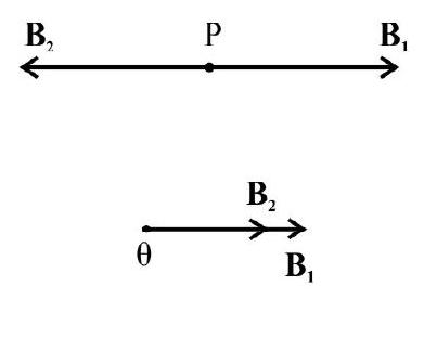
$~$
$$ \mathbf{B}=\mathbf{B} _{1}+\mathbf{B} _{2}=\mu _{0} \mathrm{i} $$
Hence option(1) is correct
Easy
Force between two long Parallel Current Carrying Conductors
27. Two long parallel straight wires $P$ and $Q$, seperated by a distance of $10 \mathrm{~cm}$ in air, carry current of $2 \mathrm{~A}$ and $5 \mathrm{~A}$, respectively, in opposite directions. Then the force, on $20 \mathrm{~cm}$ length of wire $Q$, is
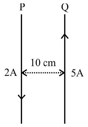 $~$
$~$
(1) $2 \times 10^{-7} \mathrm{~N}$, perpendicular to the length of $\mathrm{Q}$ and acts towards $\mathrm{P}$
(2) $2 \times 10^{-6} \mathrm{~N}$, perpendicular to the length of $\mathrm{Q}$ and acts away from $\mathrm{P}$
(3) $2 \times 10^{-6} \mathrm{~N}$, and acts towards $\mathrm{P}$
(4) $2 \times 10^{-7} \mathrm{~N}$, and acts away from $\mathrm{P}$
Show Answer
Solution:
$$ \begin{aligned} |\mathbf{F}|= & \frac{\mu _{0}}{4 \pi} \frac{2 \mathrm{I} _{1} \mathrm{I} _{2}}{\mathrm{r}} \times \mathrm{L} \\ & \frac{\mu _{0}}{4 \pi} \frac{2 \times 2 \times 5 \times 0.2}{0.1} \mathrm{~N}=2 \times 10^{-6} \mathrm{~N} \end{aligned} $$
The direction of $\mathbf{F}$ will be perpendicular to the length $Q$ and it acts away from $P$. (F between ‘unlike currents’, is a force of repulsion)
Hence option(2) is correct
Easy
Motion of Changed Particle in a Magnetic Field
28. A particle of charge $q$ and mass $m$, moves in a circular orbit of radius $r$, with angular speed $\omega$. The ratio of the magnitude of its magnetic moment, to that of its angular momentum, is given by
(1) $\frac{\mathrm{q}}{2 \mathrm{~m}}$
(2) $\frac{\omega}{2 \mathrm{~m}}$
(3) $\frac{\mathrm{q} \omega}{2 \mathrm{~m}}$
(4) $\mathrm{q} \omega$
Show Answer
Correct Answer: (1)
Solution:
The magnetic moment $|\mathbf{M}|=\mathrm{iA}=\mathrm{q}\left(\frac{\omega}{2 \pi}\right)\left(\pi \mathrm{r}^{2}\right)=\frac{\mathrm{q} \omega \mathrm{r}^{2}}{2}$
Angular momentum $=\mathrm{I} \omega=\left(\mathrm{mr}^{2} \omega\right)$
Hence $\frac{M}{L}=\frac{\frac{q \omega r^{2}}{2}}{m^{2} \omega}=\frac{q}{2 m}$
Hence option (1) is correct.
Easy
Force of Charged Particle in Magnetic Field
29. An electric current ’ $i$ ’ enters, and leaves, a uniform circular wire of radius ’ $a$ ’ through diametrically opposite points, A charged particle q, moving along the axis of circular wire, passes through its centre at speed ’ $v$ ‘. The magnetic force acting on the particle, when it passes through the centre, has a magnitude
(1) $q v \frac{\mu _{0} i}{2 a}$
(2) $q v \frac{\mu _{0} \mathrm{i}}{4 \mathrm{a}}$
(3) $q v \frac{\mu _{0} i}{2 \pi a}$
(4) zero
Show Answer
Correct Answer: (4)
Solution:
Explanation: When current enters into wire, it gets divided into two equal parts; these meet at a point, diametrically opposite, when leaving the circular wire. Hence the two halves of this wire produce (equal magnitude) magnetic fields at the centre, which act in opposite directions. Therefore the net magnetic field at centre is zero. Hence the particle, while passing through centre, experiences no force; $[\mathbf{F}=\mathrm{q} \mathbf{v} \times \mathbf{B}]$.
Hence option(4) is correct
Average
Motion of Charged Particle in Electric and Magnetic Fields
30. A uniform magnetic field, $0.75 \mathrm{~T}$, is set up over a small region by using a pair of co-axial circular coils. In the same region a uniform electrostatic field of magnitude $9 \times 10^{5} \mathrm{~V} / \mathrm{m}$ is maintained in a direction normal to the axis of coils. A narrow beam, of charged particles, all accelerated through $15 \mathrm{KV}$, enters the region in a direction perpendicular to both the axis of coil and the electrostatic field. Under these conditions the beam remains undeflected. Then the particles present in the beam, could be
(1) electrons
(2) ionized hydrogen atoms
(3) deutronions
(4) alpha particles
Show Answer
Correct Answer: (3)
Solution:
Under the specified conditions the beam will remain undefined when
$$ \mathrm{Bqv}=\mathrm{qE} \quad \text { or } \quad \mathrm{v}=\frac{\mathrm{E}}{\mathrm{B}} $$
When a charged particle, of charge $q$, is accelerated through a potential $V$, the gain in the energy of the particle is $\mathrm{qV}$.
Hence $\frac{1}{2} \mathrm{mv}^{2}=\mathrm{qV}$
$\therefore \frac{\mathrm{q}}{\mathrm{m}}=\frac{1}{2} \frac{\mathrm{v}^{2}}{\mathrm{~V}}$
Substituting the given values, the value of $\frac{\mathrm{q}}{\mathrm{m}}$ obtained is $4.8 \times 10^{7} \frac{\mathrm{C}}{\mathrm{kg}}$
Now we have to see which particle has the same value of $\frac{\mathrm{q}}{\mathrm{m}}$
For deutrion ions, we have
$$ \frac{\mathrm{q}}{\mathrm{m}}=\frac{1.6 \times 10^{-19}}{\left(2 \times 1.67 \times 10^{-27}\right)} \frac{\mathrm{C}}{\mathrm{kg}}=4.8 \times 10^{7} \frac{\mathrm{C}}{\mathrm{kg}} $$
Hence the particle in the beam could be deuterium ions.
Hence option(3) is correct
Average
Force between two long Parallel Current Carrying Conductors
31. A long wire $A B$ is placed on a table. A wire $x y($ mass $=m)$, of length, $z$, is kept parallel to, and above $A B$. xy can slide up and down on two vertical wires. The two wires are carrying currents $I _{1}$ and $I _{2}$ respetively. The wire $x y$ will settle at a distance $d$ above the wire $A B$, where d equals (nearly).
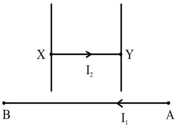
$~$
(1) $\left(\frac{\mu _{0} I _{1} I _{2}}{2 \pi \mathrm{mg}}\right) z$
(2) $\left(\frac{\mu _{0} \mathrm{I} _{1} \mathrm{I} _{2}}{2 \pi \mathrm{z}}\right)(\mathrm{mg})$
(3) $\frac{4 \pi \mathrm{z}}{\mu _{0} \mathrm{I} _{1} \mathrm{I} _{2}} \times \frac{1}{\mathrm{mg}}$
(4) $\left(\frac{2 \pi z}{m g}\right)\left(\mu _{0} \mathrm{I} _{1} \mathrm{I} _{2}\right)$
Show Answer
Correct Answer: (1)
Solution:
Let the wire $x y$ settle at a distance $\mathrm{d}$ above the wire $\mathrm{AB}$. The magnetic force, on wire $x \mathrm{y}$, of length $\mathrm{z}$, due to current in $\mathrm{AB}$ is (nearly).
$$ |\mathbf{F}|=\frac{\mu _{0}}{2 \pi} \frac{\mathrm{I} _{1} \mathrm{I} _{2}}{\mathrm{~d}} \mathrm{z} $$
Since the currents in wires $\mathrm{AB}$ and $x$ y are in opposite directions, this force, on $x y$, will be upwards.
The gravitational force on $x$ y acting vertically downwards will be $\mathrm{mg}$
Hence $\frac{\mu _{0}}{2 \pi} \frac{\mathrm{I} _{1} \mathrm{I} _{2}}{\mathrm{~d}} \mathrm{z}=\mathrm{mg}$
$\therefore \quad \mathrm{d}=\left(\frac{\mu _{0}}{2 \pi} \frac{\mathrm{I} _{1} \mathrm{I} _{2}}{\mathrm{mg}}\right) \mathrm{z}$
Hence option(1) is correct
Average
Motion of a Charged Particle in a Magnetic Field
32. A beam of alpha particles, accelerated through a potential $V$, enters a region, between two long parallel plates, separated by a distance a. A uniform magnetic field, B, directed normally outwards from the plane of the page, exists in the region between these two plates. The minimum value of $|\mathbf{B}|$, that can just prevent the $\alpha$-particles from colliding with the second plate, equals.
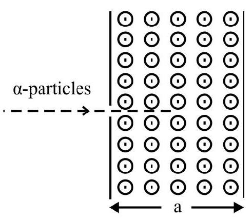
$~$
(1) $\frac{1}{\mathrm{a}}\left(\frac{\mathrm{Vm} _{\alpha}}{\mathrm{e}}\right)^{1 / 2}$
(2) $\frac{2}{\mathrm{a}}\left(\frac{2 \mathrm{Vm} _{\alpha}}{\mathrm{e}}\right)^{1 / 2}$
(3) $\frac{1}{\mathrm{a}}\left(\frac{2 \mathrm{Vm} _{\alpha}}{\mathrm{e}}\right)^{1 / 2}$
(4) $\frac{2}{\mathrm{a}}\left(\frac{\mathrm{Vm} _{\alpha}}{2 \mathrm{e}}\right)^{1 / 2}$
Show Answer
Correct Answer: (1)
Solution:
Let $\mathrm{v}$ be the velocity acquired by the alpha particles. We then have
$$ \begin{aligned} & (2 \mathrm{e}) \mathrm{V}=\frac{1}{2} \mathrm{~m} _{\alpha} \mathrm{v}^{2} \\ \therefore \quad \mathrm{v} & \sqrt{\frac{4 \mathrm{eV}}{\mathrm{m} _{\alpha}}}=2\left(\mathrm{eVm} _{\alpha}^{-1}\right)^{1 / 2} \end{aligned} $$
The (normal) magnetic field would bend the path of these $\alpha$-particles into a circle of radius $\mathrm{R}$, where
$$ \begin{gathered} \frac{\mathrm{m} _{\alpha} \mathrm{v}^{2}}{\mathrm{R}}=(2 \mathrm{e}) \mathrm{vB} \\ \therefore \quad \mathrm{R}=\frac{\mathrm{m} _{\alpha} \mathrm{v}}{2 \mathrm{eB}}=\frac{\left(\mathrm{eVm _{ \alpha } ) ^ { 1 / 2 }}\right.}{\mathrm{eB}} \\ \therefore \quad \mathrm{B}=\left(\frac{\mathrm{Vm} _{\alpha}}{\mathrm{e}}\right)^{1 / 2} \cdot \frac{1}{\mathrm{R}} \end{gathered} $$
To prevent collision with the second plate, $\mathrm{R}$ should not exceed a. Hence the minimum value of B, needed, is $\mathrm{B} _{\text {min }}=\frac{1}{\mathrm{a}}\left(\frac{\mathrm{Vm} _{\alpha}}{\mathrm{e}}\right)^{1 / 2}$
Hence option(1) is correct
Difficult
Motion of a Charged Particle in a Magnetic Field
33. A long thin solenoid, having its axis along the $x-a x i s$, has an insulated wire wound on its core. The solenoid carries a current I and has $n$ turns of wire per unit length.
An electron beam ( charge $=e$, mass $=m$ ) from a source, moves with a velocity $\mathbf{v}=v \cos \theta \hat{i}+v \sin \theta \hat{\mathbf{j}}$, in the (nearly) uniform magnetic field region of this solenoid. The path of these electrons, inside this region, would be a
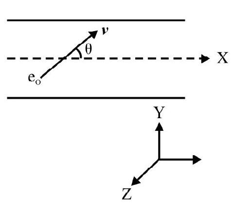
$~$
(1) circular path in the yz plane, of radius $r=\frac{m v \cos \theta}{e \mu _{0} n I}$
(2) helix (with its axis along the $x$-axis) of radius $r=\frac{m v \sin \theta}{e \mu _{0} n I}$ and pitch $p=\frac{2 \pi m v \cos \theta}{e \mu _{0} n I}$
(3) helix (with its axis along the $y$-axis) of radius $r=\frac{m v \cos \theta}{e \mu _{0} n I}$ and pitch $p=\frac{2 \pi m v \sin \theta}{\left(e \mu _{0} n I\right)}$
(4) circular path, in the $z-x$ plane, of radius $r=\frac{m v \sin \theta}{e \mu _{0} \mathrm{nI}}$
Show Answer
Correct Answer: (2)
Solution:
The long thin solenoid, produces a (nearly) uniform magnetic field, $\mathbf{B}$, around its midpoint, where
$$ \mathbf{B}=\left(\mu _{0} \mathrm{ni}\right)( \pm \hat{\mathrm{i}}) $$
Due to this field, there is no force, on the electron, due to the $x$-component $(=\mathrm{v} \cos \theta)$ of its velocity. Hence this component, of the electron’s velocity remains unaffected by the field. Due to the y-component $(=v \sin \theta)$ of its velocity, the electrons would describe a circular path, of radius $r$, where
$$ \frac{\mathrm{m}(\mathrm{v} \sin \theta)^{2}}{\mathrm{r}}=\mathrm{e}(\mathrm{v} \sin \theta) \mathrm{B} $$
Hence $\mathrm{r}=\frac{\mathrm{mv} \sin \theta}{\mathrm{eB}}=\frac{\mathrm{mv} \sin \theta}{\mathrm{e} \mu _{0} \mathrm{nI}}$
The time period, for completing this circular path, is
$$ \mathrm{T}=\frac{2 \pi \mathrm{r}}{\mathrm{v} \sin \theta}=\frac{2 \pi \mathrm{m}}{\mathrm{e} \mu _{0} \mathrm{nI}} $$
The pitch, $\mathrm{p}$, equals the distance, moved along the $\mathrm{x}$-axis, in a time $\mathrm{T}$.
Hence $p=v \cos \theta . T=\frac{2 \pi m v \cos \theta}{e \mu _{0} n I}$
Hence option(2) is correct
Difficult
Force on Current Carrying Conductor
34. A conductor, of length ’ $\ell$ ‘, is placed normally to a horizontal uniform magnetic field $B$. When a certain amount of charge is suddenly passed through it is found to jump to a height ’ $h$ ‘. The amount of charge that passed through the conductor is
(1) $\frac{\mathrm{m} \sqrt{\mathrm{gh}}}{\mathrm{B} \ell}$
(2) $\frac{\mathrm{m} \sqrt{\mathrm{gh}}}{2 \mathrm{~B} \ell}$
(3) $\frac{\mathrm{m} \sqrt{2 g h}}{\mathrm{~B} \ell}$
(4) $\frac{\mathrm{m} \sqrt{2 \mathrm{gh}}}{3 \mathrm{~B} \ell}$
Show Answer
Correct Answer: (3)
Solution:
Force $\times$ time $=$ impulse $=$ Change in linear momentum
$\int \mathrm{I} \ell \mathrm{B} \cdot \mathrm{dt}=\mathrm{mv}-0 \quad(\mathrm{v}=$ velocity acquired by the conductor $)$
$\ell \mathrm{B} \int \mathrm{dq}=\mathrm{mv}$
$\int \mathrm{dq}=\mathrm{q}=\frac{\mathrm{mv}}{\mathrm{B} \ell}$
Now $\mathrm{v}$ is related to $\mathrm{h}$ by $\mathrm{v}=\sqrt{2 \mathrm{gh}}$
$\therefore \mathrm{q}=\frac{\mathrm{m} \sqrt{2 \mathrm{gh}}}{\ell \mathrm{B}}$
Hence option (3) is correct.
Average
Motion of Charged Particle in Magnetic Field
35. A charged particle is accelerated through a potential difference of $12 \mathrm{KV}$ and acquires a speed of $10^{6} \mathrm{~m} / \mathrm{s}$. It is then injected perpendicularly into a magnetic field of strengh $0.2 \mathrm{~T}$. The radius of circle would be
(1) $12 \mathrm{~cm}$
(2) $8.33 \mathrm{~cm}$
(3) $0.833 \mathrm{~cm}$
(4) $1.2 \mathrm{~mm}$
Show Answer
Correct Answer: (1)
Solution:
Given accelerating voltage $=12 \mathrm{KV}=12 \times 10^{3} \mathrm{~V}$
$$ \mathrm{F}=\mathrm{qE}=\frac{\mathrm{qV}}{\ell} $$
$\therefore \quad$ acceleration $\mathrm{a}=\frac{\mathrm{qV}}{\mathrm{m} \ell}$
Now $\mathrm{v}^{2}=\mathrm{u}^{2}+2 \mathrm{as}$
$$ \begin{aligned} & \left(10^{6}\right)^{2}=0+2\left(\frac{\mathrm{q}}{\mathrm{m}}\right) \cdot \frac{12 \times 10^{3}}{\ell} \times \ell \\ & \Rightarrow \frac{\mathrm{q}}{\mathrm{m}}=\frac{10^{12}}{2 \times 12 \times 10^{3}}=24 \times 10^{-9} \end{aligned} $$
$\therefore \quad$ radius $\mathrm{r}=\frac{\mathrm{mv}}{\mathrm{qB}}=\frac{24 \times 10^{-9} \times 10^{6}}{0.2 \mathrm{~T}}=12 \mathrm{~cm}$
Hence option(1) is correct
Average
Force Experienced by a Current Carrying Conductor
36. A wire is bent in the form of an equilateral triangle of side $10 \mathrm{~cm}$ and carries a current of 5.0A. It is placed in a magnetic field $B$ of magnitude 2.0T directed perpendicular to the plane of the triangle. The force, experienced by each side of the triangle, and the net force experienced by the wire, will be
(1) $0.87 \mathrm{~N}$ and $2.6 \mathrm{~N}$, respectively
(2) $0.50 \mathrm{~N}$ and $1.5 \mathrm{~N}$, respectively
(3) $1.0 \mathrm{~N}$ and zero $\mathrm{N}$, respectively
(4) $1.0 \mathrm{~N}$ and $3.0 \mathrm{~N}$, respectively
Show Answer
Correct Answer: (3)
Solution:
The magnetic field is directed into the plane of paper and wire is in the plane of paper and carries current as shown in the figure.
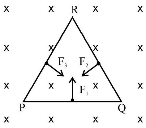
$~$
Directions of forces $\mathbf{F} _{1}, \mathbf{F} _{2}$ and $\mathbf{F} _{3}$ will be as shown in Fig.
$\left|\mathbf{F} _{1}\right|=\left|\mathbf{F} _{2}\right|=\left|\mathbf{F} _{3}\right|=\mathrm{I} \ell \times \mathbf{B}=\mathrm{I} \ell \mathrm{B} \sin \theta$
$=\mathrm{I} \ell \mathrm{B} \sin 90^{\circ}$
$=5.0 \times 0.10 \times 2.0 \mathrm{~N}=1.0 \mathrm{~N}$
Using vector rule, we get
$\mathbf{F} _{1}+\mathbf{F} _{2}+\mathbf{F} _{3}=0 \mathrm{~N}$
Difficult
Force on a Current Carrying Conductor
37. The segment, $A B$ of a wire, carrying a curent $I _{1}$ is placed perpendicular to a long straight wire carrying current $I _{2}$ as shown in figure. The magnitude of force, experienced by wire $\mathrm{AB}$, is
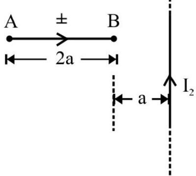
$~$
(1) $\frac{\mu _{0} I _{1} I _{2}}{2 \pi} \log _{e} 3$
(2) $\frac{\mu _{0} \mathrm{I} _{1} \mathrm{I} _{2}}{2 \pi} \log _{\mathrm{e}} 2$
(3) $\frac{\mu _{0} I _{1} I _{2}}{\pi}$
(4) $\frac{\mu _{0} I _{1} I _{2}}{2 \pi}$
Show Answer
Correct Answer: (1)
Solution:
Consider a small element of length ’ $d x$ ’ at distance $x$ from end $B$ of the wire.
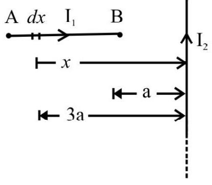
$~$
Force on this portion $\mathrm{dF}=\mathrm{I} _{1} \mathrm{~d} x \mathrm{~B}$
$$ \mathrm{dF}=\mathrm{I} _{1} \mathrm{~d} x \times \frac{\mu _{0} \mathrm{I} _{2}}{2 \pi(x+\mathrm{a})}=\frac{\mu _{0}}{4 \pi} \frac{2 \mathrm{I} _{1} \mathrm{I} _{2}}{(\mathrm{a}+x)} \mathrm{d} x $$
$$ \text{Total force} F=\int _{a}^{3 a} d F=\frac{\mu _{0} 2 I _{1} I _{2}}{4 \pi} \int _{a}^{3 a} \frac{d x}{(a+x)}$$
$$ \begin{aligned} & =\frac{\mu _{0} 2 \mathrm{I} _{1} \mathrm{I} _{2}}{4 \pi}[\ln (\mathrm{a}+x)] _{\mathrm{a}}^{3 \mathrm{a}} \\ & =\frac{\mu _{0} 2 \mathrm{I} _{1} \mathrm{I} _{2}}{4 \pi}[\ln 3 \mathrm{a}-\ln \mathrm{a}] \\ & =\frac{\mu _{0} \mathrm{I} _{1} \mathrm{I} _{2}}{2 \pi} \ln 3=\frac{\mu _{0} \mathrm{I} _{1} \mathrm{I} _{2}}{2 \pi} \log \mathrm{g} _{\mathrm{e}} 3 \end{aligned} $$
Hence option(1) is correct
Average
Force due to a Magnetic Field
38. An equilateral triangle frame, $P Q R$ of mass $M$ and side ’ $a$ ‘, is kept under the influence of (i) a magnetic force, due to an inward perpendicular magnetic field $\mathrm{B}$, and (ii) The gravitational field, as shown in the figure. The magnitude, and direction of current that should flow in the frame, so that it remains at rest, is

$~$
(1) $\mathrm{I}=\frac{2 \mathrm{mg}}{\mathrm{aB}}$, anticlockwise
(2) $\mathrm{I}=\frac{2 \mathrm{mg}}{\mathrm{aB}}$, clockwise
(3) $\mathrm{I}=\frac{\mathrm{mg}}{\mathrm{aB}}$, anticlockwise
(4) $\mathrm{I}=\frac{\mathrm{mg}}{\mathrm{aB}}$, clockwise
Show Answer
/
Correct Answer: (2)
Solution:
Effective length of the wire $=\mathrm{ST}=\ell=2 \times \frac{\sqrt{3}}{4} \mathrm{a} \cot 60^{\circ}=\frac{\mathrm{a}}{2}$
For equilibrium $\mathrm{I} \ell \mathrm{B}=\mathrm{Mg}$
$$ \mathrm{I}=\frac{2 \mathrm{mg}}{\mathrm{aB}} \quad\quad\quad\quad \left(\text { as } \ell=\frac{\mathrm{a}}{2}\right) \text { Clockwise } $$
Average
Motion of Charged Particle in Electric & Magnetic Fields
39. Uniform electric and magnetic fields, with strength $E$ and $B$, are directed along $y$-axis. A particle with specific charge $q / m$ leaves the origin in direction of $x-a x i s$ with an initial velocity $\mathrm{v} _{0}$. The angle $\alpha$, between the particles velocity vector, and the $y$-axis at the moment of leaving will be
(1) $\alpha=\tan ^{-1}\left(\frac{\mathrm{Bv} _{0}}{2 \pi \mathrm{nE}}\right)$
(2) $\alpha=\tan ^{-1}\left(\frac{\mathrm{Bv} _{0}}{\pi \mathrm{nE}}\right)$
(3) $\alpha=\tan ^{-1}\left(\frac{2 \mathrm{Bv} _{0}}{\pi \mathrm{nE}}\right)$
(4) $\alpha=\tan ^{-1}\left(\frac{2 \mathrm{Bv} _{0}}{3 \pi \mathrm{nE}}\right)$
Show Answer
Correct Answer: (1)
Solution:
The path of the particle is helix of increasing pitch, the axis is parallel to y-axis (parallel to $\mathbf{E}$ ) and plane of circle of helix is the XZ plane (perpendicular to $\mathbf{B}$ ) the particle will cross the $\mathrm{y}$-axis after time.
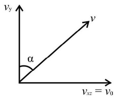
$~$
$$ \begin{aligned} \mathrm{t} & =\mathrm{nT}=\mathrm{n}\left(\frac{2 \pi \mathrm{m}}{\mathrm{qB}}\right) \\ \therefore \quad \mathrm{y} & =\frac{1}{2} \mathrm{a} _{\mathrm{y}} \mathrm{t}^{2}=\frac{1}{2}\left(\frac{\mathrm{qE}}{\mathrm{m}}\right)\left(\frac{2 \pi \mathrm{mn}}{\mathrm{qB}}\right)^{2} \\ \quad & \frac{2 \mathrm{n}^{2} \mathrm{mE} \pi^{2}}{\mathrm{qB}^{2}} \end{aligned} $$
Velocity (y-component) at this moment
$$ \begin{aligned} & \mathrm{v} _{\mathrm{y}}=\mathrm{a} _{\mathrm{y}} \mathrm{t}=\left(\frac{\mathrm{qE}}{\mathrm{m}}\right)\left(\frac{2 \pi \mathrm{mn}}{\mathrm{qB}}\right)=2 \pi \mathrm{n}\left(\frac{\mathrm{E}}{\mathrm{B}}\right) \\ & \alpha=\tan ^{-1}\left(\frac{\mathrm{v} _{x z}}{\mathrm{v} _{\mathrm{y}}}\right)=\tan ^{-1}\left(\frac{\mathrm{v} _{0} \mathrm{~B}}{2 \pi \mathrm{nE}}\right) \end{aligned} $$
Hence correct option is (1)
Average
Motion of Charged Particle in Magnetic Field
40. A proton enters a region of uniform magnetic field at point $E$ with the speed of $1.0 \times 10^{7} \mathrm{~m} / \mathrm{s}$, as shown in figure, the strength of magnetic field is $1.0 \mathrm{~T}$ and is directed into the plane of paper. Proton leaves the region of field at point ’ $F$ ’ the distance, $\mathrm{EF}$ and angle $\theta$, will respectively, be equal to (nearly)
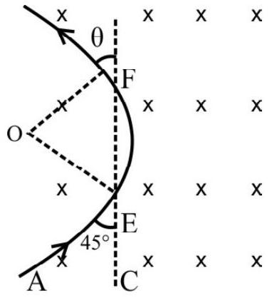 $~$
$~$
(1) $15 \mathrm{~cm}$ and $45^{\circ}$
(2) $7.5 \mathrm{~cm}$ and $22.5^{\circ}$
(3) $15 \mathrm{~cm}$ and $22.5^{\circ}$
(4) $7.5 \mathrm{~cm}$ and $45^{\circ}$
Show Answer
Correct Answer: (1)
Solution:
The radius, $\mathrm{OE}$, of the proton’s circular path is given by $\frac{\mathrm{mv}^{2}}{2}=\mathrm{qvB}$
$\therefore \mathrm{r}(=\mathrm{OE})=\frac{\mathrm{mv}}{\mathrm{qB}}$
We also have;
$\angle \mathrm{AEO}=90^{\circ}$ (Radius and tangent)
$\angle \mathrm{AEC}=45^{\circ}$ (Given)
We have $\angle \mathrm{OEF}=45^{\circ}$
$\mathrm{OF}$ and $\mathrm{OE}$ are radii of the circular arc, we have $\angle \mathrm{OFE}=45^{\circ}$
$\therefore$ angle $\theta=45^{\circ}$
Now $\mathrm{EF}=2 ~ \mathrm{OE} \cos 45^{\circ}$;
$\therefore \quad \mathrm{EF}=2 \times\left(\frac{\mathrm{mv}}{\mathrm{qB}}\right) \times \frac{1}{\sqrt{2}}$
$ \begin{aligned} & =\frac{2 \times 1.67 \times 10^{-27} \times 1.0 \times 10^{7}}{1.6 \times 10^{-19} \times 1.0} \times \frac{1}{\sqrt{2}} \mathrm{~m} \\ & =14.8 \mathrm{~cm} \approx 15 \mathrm{~cm} \end{aligned} $
Average
Force on Current Carrying Conductor in Magnetic Field
41. A rigid wire consists of semicircular portion of radius ’ $R$ ’ and two straight sections as shown in figure. It is present in a uniform perpendicular magnetic field ’ $B$ ‘. The magnetic force on the wire, when it carries a current ’ $i$ ‘, would be
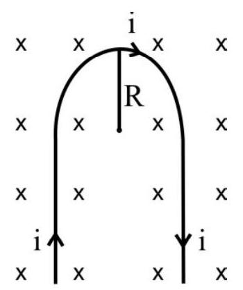
$~$
(1) (2i RB) upward
(2) (2iRB) downward
(3) (i $\pi \mathrm{RB})$ upward
(4) (i $\pi \mathrm{RB})$ downward
Show Answer
Correct Answer: (1)
Solution:
The directions of forces $\mathbf{F} _{1}, \mathbf{F} _{2}$ and $\mathbf{F} _{3}$ is marked as per the Fleming’s Left hand rule.
Since force $\mathbf{F} _{1}$ and $\mathbf{F} _{2}$ are acting in opposite directions and are equal in magnitude, they cancel each other’s effect.
Hence the total force on the given loop is due to the semi circular portion,
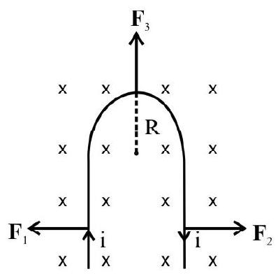
$~$
which is equal to
$$ \begin{aligned} & \mathbf{F} _{3}=\mathrm{i} \ell \times \mathbf{B} \\ \therefore \quad & \mathbf{F} _{3} \mid=\mathrm{i}(2 \mathrm{R}) \mathrm{B} \sin 90^{\circ} \\ & =2 \mathrm{iRB} \text { acting upward on the given loop. } \end{aligned} $$
Hence option(1) is correct
Average
Force on a Current Carrying Conductor in Magnetic Field
42. The force on the current carrying conductor $\mathrm{KL}$, in a niform (normal) magnetic field, $\mathrm{B}$, will be
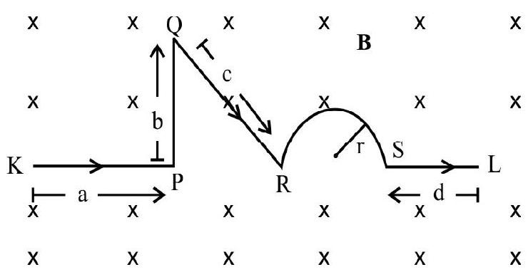
$~$
(1) $\operatorname{IB}\left(\mathrm{a}+\sqrt{\mathrm{c}^{2}-\mathrm{b}^{2}}+2 \mathrm{r}+\mathrm{d}\right)$, downwards in the plane of paper
(2) $\operatorname{IB}(\mathrm{a}+\mathrm{b}+\mathrm{c}+\pi \mathrm{r}+\mathrm{d})$, upwards in the plane of paper
(3) IB $\left(\mathrm{a}+\sqrt{\mathrm{c}^{2}-\mathrm{b}^{2}}+\pi \mathrm{r}+\mathrm{d}\right)$, upwards in the plane of paper
(4) $\operatorname{IB}\left(\mathrm{a}+\sqrt{\mathrm{c}^{2}-\mathrm{b}^{2}}+\mathrm{r}+\mathrm{d}\right)$, upwards in the plane of paper
Show Answer
Correct Answer: (4)
Solution:
Net force from $\mathrm{K}$ to $\mathrm{L}$
We have; $\mathrm{dF}=\mathrm{I}(\mathrm{d} \boldsymbol{\ell} \times \mathbf{B})$
$\therefore \quad \mathrm{F}=\int _{\mathrm{K}}^{\mathrm{L}} \mathrm{dF}=\int _{\mathrm{K}}^{\mathrm{P}} \mathrm{I}\left(\mathrm{d} \ell _{1} \times \mathbf{B}\right)+\int _{\mathrm{P}}^{\mathrm{Q}} \mathrm{I}\left(\mathrm{d} \ell _{2} \times \mathbf{B}\right)+\int _{\mathrm{Q}}^{\mathrm{R}} \mathrm{I}\left(\mathrm{d} \ell _{3} \times \mathbf{B}\right)+\int _{\mathrm{R}}^{\mathrm{S}} \mathrm{I}\left(\mathrm{d} \boldsymbol{\ell} _{4} \times \mathbf{B}\right)+\int _{\mathrm{S}}^{\mathrm{L}} \mathrm{I}\left(\mathrm{d} \boldsymbol{\ell} _{5} \times \mathbf{B}\right)$
$\mathbf{F} _{\text {net }}=\operatorname{IB}\left(\mathrm{a}+\sqrt{\mathrm{c}^{2}-\mathrm{b}^{2}}+2 \mathrm{r}+\mathrm{d}\right)$ upwards in the plane of paper.
Hence option(4) is correct
Difficult/Average
Motion of Charged Particle in Magnetic Field
43. An electron gun $\mathbf{G}$ emits electrons of energy $2 \mathrm{KeV}$ travelling along the positive $x$-direction. The electrons are required to hit the spot of $S$ where $G S=0.1 \mathrm{~m}$ and the line GS makes an angle of $60^{\circ}$ with the $x$-axis as shown in figure. $A$ uniform magnetic field $B$, parallel to GS, exists in the region outside the electron gun. The minimum value of magnetic field, $B$, needed to make the electron hit at $S$, well be
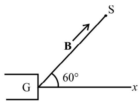
$~$
(1) $2.37 \times 10^{-4} \mathrm{~T}$
(2) $4.73 \times 10^{-4} \mathrm{~T}$
(3) $1.58 \times 10^{-4} \mathrm{~T}$
(4) $9.46 \times 10^{-4} \mathrm{~T}$
Show Answer
Correct Answer: (2)
Solution:
For the electron to hit the target, distance GS should be a multiple of the pitch of its helical path
$$ \mathrm{GS}=\mathrm{np} $$
where $\mathrm{n}=$ integer, $\mathrm{p}=$ pitch
For minimum distance $\mathrm{n}=1$
$\therefore \quad \mathrm{GS}=\mathrm{p}=\left(\frac{2 \pi \mathrm{m}}{\mathrm{qB}}\right)(\mathrm{v} \cos \theta)=\frac{2 \pi}{\mathrm{qB}}(\mathrm{mv}) \cos \theta$
$\therefore \mathrm{p}=\frac{2 \pi \sqrt{2 \mathrm{mk}} \cos \theta}{\mathrm{qB}} \quad(\because \mathrm{mv}=\sqrt{2 \mathrm{mk}})$
Hence, $B=\frac{2 \pi \sqrt{2 m k} \cos \theta}{q p}$
$$ \begin{aligned} & =\frac{2 \times 3.14 \sqrt{2 \times 9.1 \times 10^{-31} \times 2 \times 10^{3} \times 1.6 \times 10^{-19}} \times \frac{1}{2}}{1.6 \times 10^{-19} \times 0.1} \\ & =4.73 \times 10^{-4} \mathrm{~T} \end{aligned} $$
Hence option(2) is correct
Average
Force due to Magnetic Field
44. A thin, $50 \mathrm{~cm}$ long metal bar, with mass $750 \mathrm{~g}$ rests on, but in not attached to, two metallic supports in a $0.450 \mathrm{~T}$ magnetic field as shown in figure. A battary and resistance $\mathrm{R}(=25 \Omega)$, in series, are connected to the support. The maximum voltage, the battery can have without breaking the circuit at the supports, will be
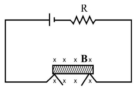
$~$
(1) $600 \mathrm{~V}$
(2) $817.5 \mathrm{~V}$
(3) $824.5 \mathrm{~V}$
(4) $807.25 \mathrm{~V}$
Show Answer
Correct Answer: (2)
Solution:
FBD of metal bar, for metal to be in equilibrium.
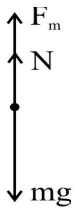 $~$
$~$
$$ \begin{aligned} & \mathrm{F} _{\mathrm{m}}+\mathrm{N}=\mathrm{mg} \\ & \mathrm{F} _{\mathrm{m}}=\mathrm{mg}-\mathrm{N} \\ & \mathrm{I} \ell \mathrm{B}=\mathrm{mg}-\mathrm{N} \\ & \frac{\mathrm{V}}{\mathrm{R}} \ell \mathrm{B}=\mathrm{mg}-\mathrm{N} \\ & \mathrm{V}=\frac{\mathrm{R}}{\ell \mathrm{B}}(\mathrm{mg}-\mathrm{N}) \end{aligned} $$
For maximum voltage, $\mathrm{N}=0$
$\therefore \quad \mathrm{V} _{\mathrm{m}}=\frac{\mathrm{R}}{\ell \mathrm{B}} \mathrm{mg}$
$$ \begin{aligned} & =\frac{25 \times 750 \times 10^{-3} \times 9.8}{50 \times 10^{-2} \times 0.450} \mathrm{~V} \\ & =817.5 \mathrm{~V} \end{aligned} $$
Hence option(2) is correct
Difficult
Force between two Parallel Current Carrying Conductors
45. A long horizontal wire $\mathrm{AB}$, which is free to move in a vertical plane, and carries a steady current of $20 \mathrm{~A}$, is in equilibrium at a height of $0.01 \mathrm{~m}$ over another parallel long wire $C D$. The wire $C D$ is fixed in a horizontal plane and carries a stready current of $30 \mathrm{~A}$. As shwon in figure. If wire $A B$ is very slightly depressed and released, the time period of its simple harmonic oscillations, will be
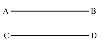
$~$
(1) 9.86 second
(2) 3.14 second
(3) 0.1 second
(4) 0.2 second
Show Answer
Correct Answer: (4)
Solution:
Force per unit length on conductor $\mathrm{AB}$
$$ \mathrm{f}=\frac{\mu _{0}}{4 \pi} \frac{2 \mathrm{I} _{1} \mathrm{I} _{2}}{\mathrm{r}} $$
For equilibrium $\mathrm{f}=\frac{\mathrm{m}}{\ell} \mathrm{g}=\lambda \mathrm{g}$
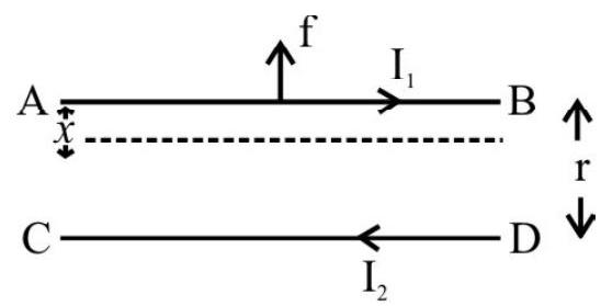
$~$
Hence $\lambda \mathrm{g}=\frac{\mu _{0}}{4 \pi} \frac{2 \mathrm{I} _{1} \mathrm{I} _{2}}{\mathrm{r}}$
Net force on unit length of wire $A B$
$\lambda \mathrm{a}=\lambda \mathrm{g}-\mathrm{f}$ ’ $\quad$ where ’ $\mathrm{a}$ ’ is the acceleration
or $\lambda \mathrm{a}=\frac{\mu _{0}}{4 \pi} \frac{2 \mathrm{I} _{1} \mathrm{I} _{2}}{\mathrm{r}}-\frac{\mu _{0}}{4 \pi} \frac{2 \mathrm{I} _{1} \mathrm{I} _{2}}{(\mathrm{r}-x)}$ $\lambda \mathrm{a}=-\frac{\mu _{0}}{4 \pi} \frac{2 \mathrm{I} _{1} \mathrm{I} _{2} \mathrm{x}}{\mathrm{r}(\mathrm{r}-x)}$
When $x < < \mathrm{r} \quad \lambda \mathrm{a}=-\frac{\mu _{0}}{4 \pi} \frac{2 \mathrm{I} _{1} \mathrm{I} _{2} x}{\mathrm{r}^{2}}$
$\mathrm{a}=-\left(\frac{\mu _{0} \mathrm{I} _{1} \mathrm{I} _{2}}{2 \lambda \pi \mathrm{r}^{2}}\right) x$
$\therefore$ For the motion to be simple harmonic we must have $\mathrm{a}=-\omega^{2} x$
Hence $\omega^{2}=\frac{\mu _{0} I _{1} I _{2}}{2 \lambda \pi r^{2}}$
$\omega=\frac{1}{\mathrm{r}} \sqrt{\frac{\mu _{0} \mathrm{I} _{1} \mathrm{I} _{2}}{2 \lambda \pi}}$
Now $\mathrm{T}=\frac{2 \pi}{\omega}=2 \pi \sqrt{\frac{2 \lambda \pi \mathrm{r}^{2}}{\mu _{0} \mathrm{I} _{1} \mathrm{I} _{2}}}=2 \pi \sqrt{\frac{2 \lambda \pi \mathrm{r}^{2}}{2 \pi \mathrm{r} \lambda \mathrm{g}}}=2 \pi \sqrt{\frac{\mathrm{r}}{\mathrm{g}}}$
Substituting values,
$\mathrm{T}=2 \times 3.14 \sqrt{\frac{0.01}{9.8}}$ second $=0.2$ second
Hence option(4) is correct
Average
Force on Charged Particle in Magnetic Field & Electric Field
46. An electron moves straight inside a charged parallel plate capacitor of uniform surface charge density $\sigma$. The space, between the plates, has a constant magnetic field $B$, as shown in figure. Neglecting gravity, the time taken to cover straight line distance, ’ $\ell$ ‘, by as electron, moving with a constant velocity $v$, in the capacitor, will be
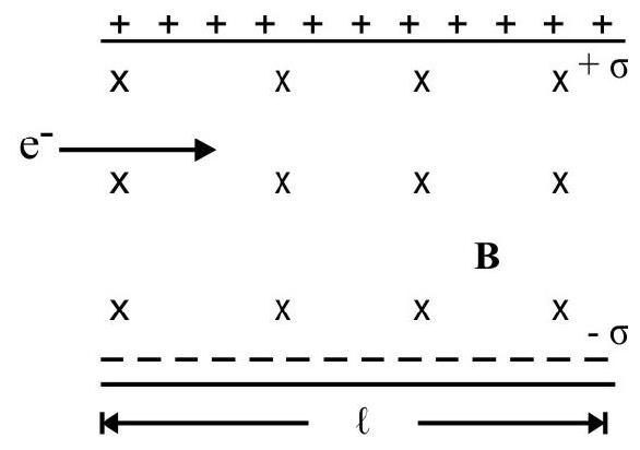
$~$
(1) $\frac{\sigma}{\varepsilon _{0} \ell \mathrm{B}}$
(2) $\frac{\sigma}{\varepsilon _{0} \mathrm{~B}}$
(3) $\frac{\varepsilon _{0} \ell \mathrm{B}}{\sigma}$
(4) $\frac{\varepsilon _{0} \mathrm{~B}}{\sigma}$
Show Answer
Correct Answer: (3)
Solution:
Net electric field between the plates of capacitor $\mathbf{E}=\mathbf{E} _{1}+\mathbf{E} _{2}$
$$ =\frac{\sigma}{2 \varepsilon _{0}}+\frac{\sigma}{2 \varepsilon _{0}}=\frac{\sigma}{\varepsilon _{0}} $$
$\therefore$ Force on the electron due to electric field
$$ \left|\mathrm{F} _{\mathrm{e}}\right|=\mathrm{eE} $$
Force on the particle due to magnetic field
$$ \mathrm{F} _{\mathrm{m}}=\mathrm{e}(\mathbf{v} \times \mathbf{B})=\mathrm{evB} $$
For unaccelerated straight line motion $\mathbf{F} _{\text {net }}=\mathbf{F} _{\mathrm{e}}+\mathbf{F} _{\mathrm{m}}=0$
Hence $\mathrm{eE}=\mathrm{evB}$ which gives $\mathrm{v}=\frac{\mathrm{E}}{\mathrm{B}}=\frac{\sigma}{\varepsilon _{0} \mathrm{~B}}$
Hence, time of motion, inside the capacitor, is
$$ \mathrm{t}=\frac{\ell}{\mathrm{v}}=\frac{\varepsilon _{0} \ell \mathrm{B}}{\sigma} $$
Hence option (3) is correct
Difficult
Force on Current Carrying Conductors
47. Three infinitely long thin wires, each car rying current $\mathrm{i}$, in the same direction, ar e in the $x$ $y$ plane of gravity free space. The central wire is along the $y$-axis while other two are along $x= \pm \mathrm{d}$. If the central wire is displaced, along the $\mathbf{z}$-direction, by a small amount, and released, it starts executing simple harmonic motion. If the linear density of wire is $\lambda$. The frequency of oscillations will be
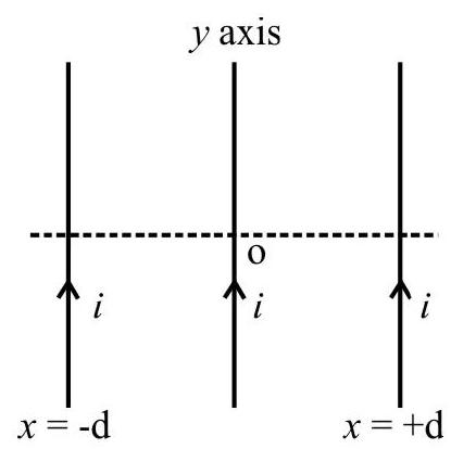
$~$
(1) $\frac{\mathrm{i}}{2 \pi \mathrm{d}} \sqrt{\frac{\mu _{0}}{\pi \lambda}}$
(2) $\frac{i}{d} \sqrt{\frac{\mu _{0}}{\pi \lambda}}$
(3) $\frac{\mathrm{i}}{\pi \mathrm{d}} \sqrt{\frac{\mu _{0}}{\pi \lambda}}$
(4) $\frac{2 \mathrm{i}}{\pi \mathrm{d}} \sqrt{\frac{\mu _{0}}{\pi \lambda}}$
Show Answer
Correct Answer: (1)
Solution:
Let the $+\mathrm{y}$-axis be perpendicular (into) the plane of paper $x$ and $\mathrm{z}$ axis are in the plane of the paper.
After displacing the central wire, along the $\mathrm{z}$ axis a little, through a distance, ’ $\mathrm{z}$ ‘, say
Force/length, acting on the central wire, is $\mathrm{F} _{\mathrm{net}}=2 \mathrm{~F} \cos \theta=2 \times \frac{\mu _{0} \mathrm{i}^{2}}{2 \pi \mathrm{r}} \times \frac{\mathrm{z}}{\mathrm{r}}$
$$ \mathrm{F} _{\text {net }}=\frac{\mu _{0} \mathrm{i}^{2}}{\pi \mathrm{r}^{2}} \mathrm{z}=\frac{\mu _{0} \mathrm{i}^{2}}{\pi\left(\mathrm{d}^{2}+\mathrm{z}^{2}\right)} \mathrm{z} $$
If $\mathrm{z} < < \mathrm{d}$, then $\mathrm{F} _{\text {net }}=-\frac{\mu _{0} \mathrm{z}^{2}}{\pi \mathrm{d}^{2}}$. $\mathrm{z}$
Let ’ $a$ ’ be the acceleration in the wire in this position then
$\mathrm{F} _{\text {net }}=\lambda \mathrm{a}=-\frac{\mu _{0} \mathrm{i}^{2}}{\pi \mathrm{d}^{2}} \mathrm{z} \quad \therefore \mathrm{a}=-\frac{\mu _{0} \mathrm{i}^{2}}{\pi \lambda \mathrm{d}^{2}} \mathrm{z}$
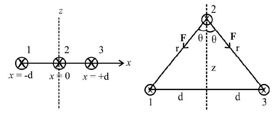
$~$
Hence $\omega^{2}=\frac{\mu _{0} \mathrm{i}^{2}}{\pi \lambda \mathrm{d}^{2}} \Rightarrow v^{2}=\frac{\mu _{0} \mathrm{i}^{2}}{4 \pi^{3} \lambda \mathrm{d}^{2}} \Rightarrow v=\frac{\mathrm{i}}{2 \pi \mathrm{d}} \sqrt{\frac{\mu _{0}}{\pi \lambda}}$
Hence option(1) is correct
Average
Torque Acting on a Current Loop
48. A circular loop, of radius $20 \mathrm{~cm}$, is placed (in the $x-y$ plane), in a uniform magnetic field of strength 2.0 tesla, that is directed as shown, in the xy plane. The loop carries a current 1.0A in the direction shown in figure. The torque acting on the loop will be.

$~$
(1) $0.18(\hat{\mathrm{i}}-\hat{\mathrm{j}})$
(2) $0.18(\hat{\mathrm{i}}+\hat{\mathrm{j}})$
(3) $0.18(\hat{\mathrm{i}}+\hat{\mathrm{k}})$
(4) $0.18 \hat{\mathrm{k}}$
Show Answer
Correct Answer: (1)
Solution:
The magnetic field can be expressed as
$$ \mathbf{B}=2 \cos 45^{0} \hat{i}+2 \sin 45 \hat{j}=\sqrt{2}(\hat{i}+\hat{j}) T $$
Magnetic moment is always perpendicular to the plane of loop. In the given figure its direction will be into the plane of paper.
$\therefore \quad \mathbf{M}=\mathrm{NiA}=\left[(1)(1.0)(0.2)^{2}(-\hat{\mathrm{k}})\right] \mathrm{Am}^{2}=0.04 \pi(-\hat{\mathrm{k}}) \mathrm{Am}^{2}$
$\therefore$ Torque $\vec{\tau}=\mathbf{M} \times \mathbf{B}$
$$ \begin{aligned} & =0.04 \pi(-\hat{k}) \times \sqrt{2}(\hat{i}+\hat{j})=-0.04 \pi \sqrt{2}(\hat{j}-\hat{i}) \\ & =0.04 \times 3.14 \times 1.414(\hat{j}-\hat{i}) \simeq 0.18(\hat{i}-\hat{j}) N-m \end{aligned} $$
Hence option (1) is correct.
Average
Force on Conductor
49. A conductor, of length ’ $\ell$ ‘, lies along the $x$-axis. It carries a current $i$ (along the $x$-axis). The magnetic field, acting in the region is $B=B _{0} \hat{k}$, where $r$ is the distance of the field point from the origin. The amount of work done in turning it at a constant angular speed, through a right angle, (as shown in figure), will be
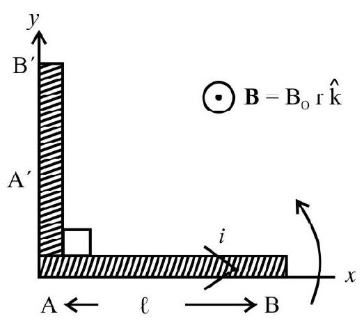
$~$
(1) $\frac{\mathrm{IB} _{0} \ell^{2} \pi}{3}$
(2) $\frac{\mathrm{IB} _{0} \ell^{3} \pi}{4}$
(3) $\frac{\mathrm{IB} _{0} \ell^{3} \pi}{6}$
(4) $\frac{\mathrm{IB} _{0} \ell^{3} \pi}{2}$
Show Answer
Correct Answer: (3)
Solution:
Force acting on small element of the conducting rod at distance $x$ fromend $\mathrm{A}$
$ \mathrm{dF}=\operatorname{Id} x \mathrm{~B} _{0} x $
Torque about A due to this force
$ \mathrm{d} \tau=x \mathrm{dF}=\operatorname{Id} x \mathrm{~B} _{0} x^{2} $
Total torque $\tau=\mathrm{IB} _{0} \int _{0}^{\ell} x^{2} \mathrm{~d} x=\frac{\mathrm{IB} _{0} \ell^{3}}{3}$
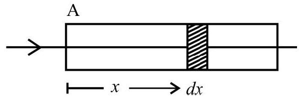
$~$
External torque required to rotate $==\frac{\mathrm{IB} _{0} \ell^{3}}{3}$
Hence work done $\omega=\tau \theta=\frac{\mathrm{IB} _{0} \ell^{3}}{3} \times \frac{\pi}{2}=\frac{\mathrm{I} {\mathrm{\pi}} \mathrm{B} _{0} \ell^{3}}{6}$
Hence option (3) is correct
50. A straight conductor, of mass ’ $m$ ‘, and carrying a current $i$, is hinged at one end and placed in a plane perpendicular to the magnetic field of intensity $B$ as shown in figure. At any moment, if the conductor is let free then the angular acceleration of the conductor (neglecting the effects of gravity) will be
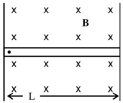
$~$
(1) $\frac{2 \mathrm{iB}}{3 \mathrm{~m}}$
(2) $\frac{3 \mathrm{iB}}{2 \mathrm{~m}}$
(3) $\frac{\mathrm{iB}}{2 \mathrm{~m}}$
(4) $\frac{3 \mathrm{iB}}{4 \mathrm{~m}}$
Show Answer
Correct Answer: (2)
Solution:
Force acting on the elementary portion of the current carrying conductor
$$ \mathrm{dF}=\mathrm{i}(\mathrm{dr}) \mathrm{B} \sin 90^{\circ}=\mathrm{idrB} $$
Torque of this force, on this element, about ’ 0 '
$$ \mathrm{d} \tau=\mathrm{rdF} $$
Hence total torque about $0=\int \mathrm{d} \tau=\int \mathrm{r}(\mathrm{iBdr})$
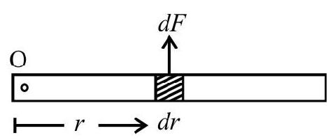
$~$
$$ \tau=\mathrm{IB} \int _{0}^{\mathrm{L}} \mathrm{r} d r=\frac{\mathrm{iBL}^{2}}{2} $$
Angular acceleration $\alpha=\frac{\tau}{\mathrm{MI}}=\frac{\tau}{\text { Moment of inertia }}$
Here Moment of inertia $=\frac{\mathrm{mL}^{2}}{3}$
Hence $\alpha=\frac{3 \mathrm{IBL}^{2}}{2 \cdot \mathrm{mL}^{2}}=\frac{3 \mathrm{iB}}{2 \mathrm{~m}}$
Hence option(2) is correct
Easy
Moving Coil Galvanometer
51. A galvanometer coil is would on the same frame but with a wire of one fourth of the original diameter and 10 times the original number of turns. The ratio of the new deflections to the ‘old’ deflection, per $\mathrm{mA}$ of current the same current as before is supplied to it will be.
(1) $\frac{5}{2}$
(2) $\frac{5}{8}$
(3) $\frac{5}{4}$
(4) $\frac{5}{16}$
Show Answer
Correct Answer: (2)
Solution:
Let dashed quantities denote the new values and undashed quantities the ‘old’ values.
$\therefore \quad \mathrm{d}^{\prime}=\frac{\mathrm{d}}{4} \quad\quad \mathrm{n}^{\prime}=10 \mathrm{n}$
The deflection, $\theta$, is related to the current $\mathrm{I}$ by the relation $\mathrm{I}=\frac{\mathrm{c}}{\mathrm{nAB}} \theta$
$\therefore \quad \mathrm{I}=\frac{4 \mathrm{c}}{\mathrm{n} \lambda \mathrm{d}^{2} \mathrm{~B}} \theta$
and $I=\frac{4 \mathrm{c} \theta^{\prime}}{10 \mathrm{n} \pi \mathrm{d}^{2} \mathrm{~B}}=\frac{64 \mathrm{c} \theta^{\prime}}{10 \pi \mathrm{nBd}^{2}}$
$\therefore \quad \frac{4 \mathrm{c} \theta}{\mathrm{n} \pi \mathrm{Bd}^{2}}=\frac{64 \mathrm{c} \theta^{\prime}}{10 \pi \mathrm{nBd}^{2}}$
or $\quad \frac{\theta^{\prime}}{\theta}=\frac{5}{8}$
Hence option(2) is correct
Easy
Moving Coil Galvonometer
52. A galvanometer is sensitive if it shows as large a deflection as possible when a very small current is passed through it. To achieve improved sensitivity of the galvanometer, the manifacturers prefer to
(1) increase $\mathrm{n}$ as well as $\mathrm{k}$
(2) decrease $\mathrm{k}$ and increase $\mathrm{A}$
(3) increase $n$ and $\mathrm{A}$
(4) increase $\mathrm{B}$ and decrease $\mathrm{k}$
Show Answer
Correct Answer: (4)
Solution:
The value of $n$ cannot be increased beyond a certain limit. This can make galvanometer bulky also its increase the resistance of the galvanometer.
Also the area A cannot be increased beyond a limit. It will make galvanometer unmanagable in size and the coil will then not be in auniform field. How ever $\mathbf{B}$ can be increased using a powerful source of magnetic field and $\mathrm{k}$ can be decreased by using materials like quartz or phospher bronze as suspension strips.
Easy
Moving Coil Galvonometer
53. In the design of a moving coil galvanometer a soft iron cylinder is kept concentric with cylinderical concave pole pieces and enclosed by them. The role of the soft iron cylinder is to
(1) provide stability to the suspension system of the galvanometer
(2) provide a uniform field between the pole pieces of the magnet used
(3) to provide a stronger field
(4) provide (along with the curved pole pieces) a radial field between the hole pieces of the magnet.
Show Answer
Correct Answer: (4)
Solution:
Informative
Average
Moving Ciol Galvanometer
54. A moving coil galvanometer is placed in a radial magnetic field of $0.2 \mathrm{wb} / \mathrm{m}^{2}$. The coil of the galvanometer has 200 turns and its area is $1.6 \times 10^{-4} \mathrm{~m}^{2}$. The restoring couple constant of the suspension fibre is $10^{-6}(\mathrm{~N}-\mathrm{m}) /$ degree. The maximum current this galvanometer can measure if its scale can accomodate only up to $45^{\circ}$ deflection, $P$ would be (nearly)
(1) $7.0 \mathrm{~mA}$
(2) $7.0 \mu \mathrm{A}$
(3) $14.0 \mathrm{~mA}$
(4) $14.0 \mu \mathrm{A}$
Show Answer
Correct Answer: (1)
Solution:
The maximum current, that the galvanometer can measure is the one which can produce a deflection of $45^{\circ}$.
For the galvanometer, we have
$ \mathrm{niBA}=\mathrm{c} \theta $
$\therefore \quad i=\left(\frac{c}{n B A}\right) \theta$
Thus $\mathrm{i} _{\max }=\frac{10^{-6} \times 45}{200 \times 0.2 \times 1.6 \mathrm{x}^{-4}} \mathrm{~A} \simeq 7 \times 10^{-3} \mathrm{~A}$
$ \approx 7 \mathrm{~mA} $
Hence option(1) is correct
Average
Voltmeter
55. Two resistor $400 \Omega$ and $800 \Omega$ are connected in series will a $6 \mathrm{~V}$ battry. A voltmeter of 10000 resistance is used to measure the potential difference across $400 \Omega$ resistor. The reading of the voltmeter would be
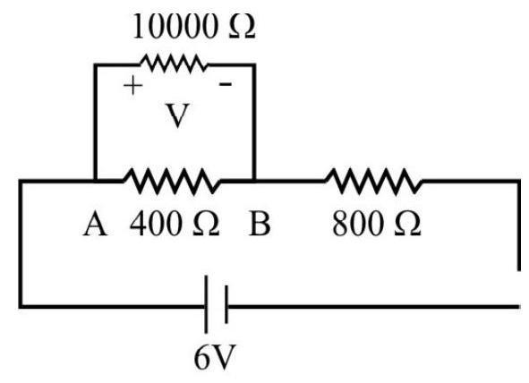
$~$
(1) $2.25 \mathrm{~V}$
(2) $1.95 \mathrm{~V}$
(3) $1.75 \mathrm{~V}$
(4) $1.55 \mathrm{~V}$
Show Answer
Correct Answer: (2)
Solution:
Since $400 \Omega$ and $10000 \Omega$ resistors are in parallel, there equivalent resistance is
$$ \mathrm{R} _{\mathrm{eq}}=\frac{400 \times 10000}{400+10000} \Omega=\frac{5000}{13} \Omega $$
Total resistance of the circuit
$$ \mathrm{R}=\left(\frac{5000}{13}+800\right) \Omega=\frac{15400}{13} \Omega $$
Current in the circuit $\mathrm{I}=\left[\frac{(6)}{\left(\frac{15400}{13}\right)}\right]^{\mathrm{A}}=\frac{39}{7700} \mathrm{~A}$
Potential difference across $A$ and $B$ is given
$$ =\frac{39}{7700} \times \frac{5000}{13}=1.95 \mathrm{~V} $$
Hence option (2) is correct.
Average
Voltmeter
56. A voltmeter reads 5 volts at full scale deflection and is graded (according to its resistance per volt at full scale deflection) as $5000 \Omega / \mathrm{V}$. It is desired to convert it into a voltmeter that reads $20 \mathrm{~V}$ at full scale deflection by connecting a appropriate resistance $\mathrm{R}$ in seires with its coil. Then
(1) The value of R should be $10^{5} \Omega$ and its grading will become $2000 \Omega / \mathrm{V}$
(2) We need to have an additional resistance of $75000 \Omega$ to be connected in series and the grading will remain the same
(3) We need to have an addtional resistance of $75000 \Omega$ to be connected in series and the grading will become $2000 \Omega / \mathrm{V}$
(4) We need a resistance of $10^{5} \Omega$ and the grading will be $5000 \Omega / \mathrm{V}$
Show Answer
Correct Answer: (2)
Solution:
The grading of a voltmeter, in terms of resistance/volt, is done by dividing its resistance by the voltage that produces a full scale deflection in it.
Thus the resistance of the given voltmeter is
$$ \mathrm{R} _{\mathrm{v}}=\left(\frac{5000}{1 \mathrm{volt}} \times 5 \text { volt }\right)=25000 \Omega $$
$\therefore$ The current that will produce a full scale deflection is given by
$$ \mathrm{i} _{\max }=\frac{5}{25000} \mathrm{~A}=2 \times 10^{-4} \mathrm{~A} $$
When the voltmeter has to have a range, of $20 \mathrm{v}$, its resistance should be
$$ \mathrm{R} _{\mathrm{v}}=\frac{20}{\mathrm{i} _{\max }} \Omega=\frac{20}{2 \times 10^{-4}} \Omega=10^{5} \Omega $$
Hence an additional resistance of $\left(10^{5}-25000\right) \Omega$ i.e., $75000 \Omega$ has to be added in series to effect the conversion of the voltmeter to have a range of $20 \mathrm{v}$.
The grading of the desired converted voltmeter is $\left(\frac{10^{5}}{20}\right) \Omega / \mathrm{V}=5000 \Omega / \mathrm{V}$
Hence the option (2) is correct.
Difficult
Ammeter
57. A galvanometer, having a resistance of $100 \Omega$ gives a full scale deflection for a current of $1 \mathrm{~mA}$. The resistance, which can convent this galvanometer into an ammeter, giving full scale deflection for a current of $10 \mathrm{~A}$, is $R$. This converted meter, when connected across the terminals of a bettery ( $\mathrm{emf}=\mathrm{E})$ reads $4 \mathrm{~A}$. The current drops to $1.0 \mathrm{~A}$ when a resistance of $1.5 \Omega$ is connected in series with this converted galvanometer. The values of $R, E$ and $r$ (= internal resistance of battery) are given by
(1) $0.01 \Omega, 2 \mathrm{~V}$ and $0.98 \Omega$
(2) $0.1 \Omega, 1 \mathrm{~V}$ and $0.49 \Omega$
(3) $0.01 \Omega, 1 \mathrm{~V}$ and $0.49 \Omega$
(4) $0.001 \Omega, 0.2 \mathrm{~V}$ and $0.49 \Omega$
Show Answer
Correct Answer: (3)
Solution:
The value of $\mathrm{R}$ is obtained from the relation
$ \frac{\mathrm{G}}{\mathrm{R}}=\frac{9.999}{0.001} $
$\therefore \mathrm{R}=\frac{100 \times 1}{999.9}=0.01 \Omega$
From figure shown, we have
$ 4=\frac{E}{4+0.01} $
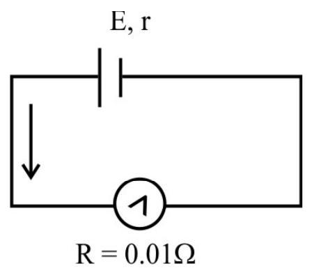
$~$
and $1.0=\frac{\mathrm{E}}{0.01+1.5+\mathrm{r}}$
or $\quad 1.51+\mathrm{r}=\mathrm{E}$
Solving above equations we get
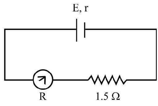
$~$
$\mathrm{E}=2$ volt
and $\mathrm{r}=0.49 \Omega$
Hence option (3) is correct.
Easy
Ammeter
58. An electrical circuit is made as shown. The galvanometer has a resistance G. With the key $K _{2}$ open, the current in the circuit is $i$. The current, in the galvanometer with key $K _{2}$ is closed and $\mathrm{S}=\mathbf{0}$, would be
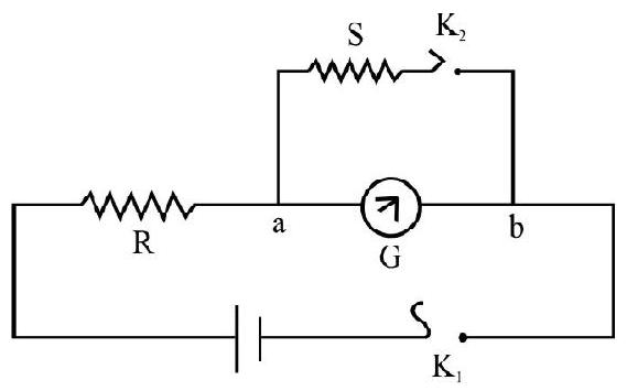
$~$
(1) $ \infty $
(2) zero
(3) $\frac{i}{2}$
(4) $\frac{E(S+G)}{R(S+G)+S G}$
Show Answer
Correct Answer: (2)
Solution:
When the key $\mathrm{K} _{2}$ open, the resistance of the circuit is $(\mathrm{R}+\mathrm{G})$. Hence
$ i=\frac{E}{R+G} $
When the key $\mathrm{K} _{2}$ is open and $\mathrm{S}=0$, all the current reaching point a would go via the zero resistance path $\mathrm{aK} _{2} \mathrm{~b}$. Hence the current through the meter would be zero.
Hence option (2) is correct.
Average
Ammeter
59. The resistance of a pivoted type galvanometer is $8 \Omega$ and the current for full scale deflection on it is $0.01 \mathrm{~A}$. This galvanometer is to be converted into an ammeter of $5 \mathrm{~A}$ range. The only shunt available is $0.02 \Omega$. The resistance, that needs to be connected in series with the galvanometer coil, is
(1) $02 \Omega$
(2) $1.98 \Omega$
(3) $2.0 \Omega$
(4) $0.198 \Omega$
Show Answer
Correct Answer: (2)
Solution:
We must have
$ I _{g}(G+R)=\left(I-I _{g}\right) 5 $
or $0.01(8+\mathrm{R})=(5-0.01)(0.02)$
Hence,
$ \mathrm{R}=\left\{\left[\frac{4.99 \times 0.02}{0.01}\right]-8\right\} \Omega=1.98 \Omega $
Hence option (2) is correct.
Average
Meters
60. An electrical circuit is shown in the figure. The meter shows a current $i$ when the key $K _{2}$ is open. The resistance of the meter is $\mathbf{G}$. Neglecting the internal resistance of the battery the value of $S$, to make the current in the meter $1 / 2$, is equal to
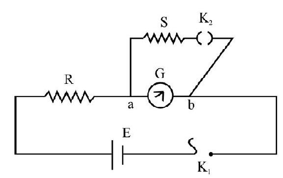
$~$
(1) $\left(\frac{R G}{R+G}\right)$
(2) $\frac{\left(\frac{G}{2}\right)}{(R+G)}$
(3) $\frac{\left(\mathrm{R}+\frac{\mathrm{G}}{2}\right)}{(\mathrm{RG})}$
(4) G
Show Answer
Correct Answer: (2)
Solution:
Denoting by $\mathrm{X}$, the equivalent resistance of the parallel combination of $\mathrm{S}$ and $\mathrm{G}$ we have
$$ \mathrm{X}=\frac{\mathrm{SG}}{\mathrm{S}+\mathrm{G}} $$
As the total resistance of the circuit is now $\mathrm{R}+\mathrm{X}$, hence the current $\mathrm{i}$ flowing in the circuit now, is given by
$$ \mathrm{i}^{\prime}=\frac{\mathrm{E}}{\mathrm{R}+\mathrm{X}}=\frac{\mathrm{E}(\mathrm{S}+\mathrm{G})}{\mathrm{R}(\mathrm{S}+\mathrm{G})+\mathrm{SG}} $$
This current $i^{\prime}$, divides inself into two paths ( $\left.a k _{2} b\right)$ and $a G b\left(i _{2}\right.$ ). If the currents in these two paths are $i _{1}$ and $\mathrm{i} _{2}$, we have
$$ \mathrm{i}^{\prime}=\mathrm{i} _{1}+\mathrm{i} _{2} $$
Since the p.d between $a$ and $b$ is one and the same we have
$$ \begin{aligned} & \mathrm{i} _{1} \mathrm{~S}=\mathrm{i} _{2} \mathrm{G} \\ & \frac{\mathrm{i} _{2}}{\mathrm{i} _{1}}=\frac{\mathrm{S}}{\mathrm{G}} \quad \quad \qquad \therefore \mathrm{i} _{2}=\frac{\mathrm{S}}{\mathrm{S}+\mathrm{G}} \mathrm{i}^{\prime} \end{aligned} $$
As per question we want $i _{2}=i / 2$
So using above derived equations we get
$$ \left(\frac{S}{S+G}\right)\left[\frac{E(S+G)}{R(S+G)+S G}\right]=\frac{1}{2}\left(\frac{E}{R+G}\right) $$
This gives $S=\frac{R G}{R+G}$
Hence option (1) is correct.
Difficult
Voltmeter
61. A voltmeter is connected across a $400 \Omega$ resistance and reads 30 volt. If the same voltmeter is connected across the $300 \Omega$ resistance, then its reading will be
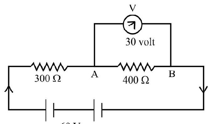
$~$
(1) 30 volt
(2) 22.5 volt
(3) 24 volt
(4) $(90 / 7)$ volt
Show Answer
Correct Answer: (2)
Solution:
Let $R _{v}$ be the resistance of the voltmeter. Then $R _{v}$ and $400 \Omega$ resistance, when connected in parallel would have an equivalent resistances given by
$$ \mathrm{R} _{1}=\frac{400 \times \mathrm{R} _{\mathrm{v}}}{\left(\mathrm{R} _{\mathrm{v}}+400\right)} $$
and the current in the circuit with correspond to
$$ \frac{60}{300+\left[\frac{400 R _{v}}{R _{v}+400}\right]}=\frac{60\left(R _{v}+400\right)}{300\left(R _{v}+400\right)+400 R _{v}} $$
According to question potential drop across $\mathrm{AB}$ is 30 volt so
$$ 30=\frac{60\left(R _{v}+400\right)}{300\left(R _{v}+400\right)+400 R _{v}} \times R _{1}=\frac{60\left(400 R _{v}\right)}{300\left(R _{v}+400\right)+400 R _{v}} $$
Solving we obtain $\mathrm{R} _{\mathrm{v}}=1200 \Omega$
Now when the voltmeter is connected across $300 \Omega$ the equivalent resistance of their parallel combination, is
$$ \frac{1200 \times 300}{1200+300} \Omega=240 \Omega $$
Now the total resistance of the circuit would be $(240+400) \Omega=640 \Omega$ and the corresponding current is $(60 / 640)$
Hence in this case reading of the voltmeter would be
$$ \frac{60}{640} \times 240=22.5 \text { Volt } $$
Hence option (2) is correct.
Average
Conversion of Galvanometer into Voltmeter and Ammeter
62. A given galvanometer can be converted into a (i) a voltmeter of range ( 0 to $\mathrm{V})$ volt by connecting a resistance, $R$, in series with its coil, (ii) an ammeter of range ( 0 to $I$ ) ampere by connecting a shunt resistance, $S$, across its coil.
The resistance (G) of the galvanometer, and the current $\left(i _{g}\right)$, needed to produce a full scale deflection in it, are then given by
(1) $\quad \mathrm{G}=\left(\frac{\mathrm{RI}-\mathrm{V}}{\mathrm{V}-\mathrm{SI}}\right) \mathrm{S} ; \mathrm{i} _{\mathrm{g}}=\left(\frac{\mathrm{V}-\mathrm{SI}}{\mathrm{R}-\mathrm{S}}\right)$
(2) $\quad \mathrm{G}=\left(\frac{\mathrm{V}-\mathrm{SI}}{\mathrm{RI}-\mathrm{V}}\right) \mathrm{S} ; \mathrm{i} _{\mathrm{g}}=\left(\frac{\mathrm{V}+\mathrm{SI}}{\mathrm{R}+\mathrm{S}}\right)$
(3) $\quad \mathrm{G}=\left(\frac{\mathrm{V}+\mathrm{SI}}{\mathrm{RI}+\mathrm{V}}\right) \mathrm{S} ; \mathrm{i} _{\mathrm{g}}=\left(\frac{\mathrm{V}-\mathrm{SI}}{\mathrm{R}-\mathrm{S}}\right)$
(4) $\quad \mathrm{G}=\left(\frac{\mathrm{RI}+\mathrm{V}}{\mathrm{V}+\mathrm{SI}}\right) \mathrm{S} ; i _{\mathrm{g}}=\left(\frac{\mathrm{V}+\mathrm{SI}}{\mathrm{R}+\mathrm{S}}\right)$
Show Answer
Correct Answer: (1)
Solution:
We know that $R=\left(\frac{V}{i _{g}}-G\right)$ and $S=\left(\frac{i _{g}}{I-i _{g}}\right) G$
$\therefore \quad \mathrm{Ri} _{\mathrm{g}}=\left(\mathrm{V}-\mathrm{i} _{\mathrm{g}} \cdot \mathrm{G}\right) \quad$ or $\quad(\mathrm{R}+\mathrm{G}) \mathrm{i} _{\mathrm{g}}=\mathrm{V}$
and $ \quad \mathrm{SI}=(\mathrm{G}+\mathrm{S}) \mathrm{i} _{\mathrm{g}} \quad$ or $\quad(\mathrm{G}+\mathrm{S}) \mathrm{i} _{\mathrm{g}}=\mathrm{SI}$
$\therefore \frac{\mathrm{R}+\mathrm{G}}{\mathrm{G}+\mathrm{S}}=\frac{\mathrm{V}}{\mathrm{SI}}$
This gives $\mathrm{G}=\left(\frac{\mathrm{RI}-\mathrm{V}}{\mathrm{V}-\mathrm{SI}}\right) \mathrm{S}$
We then get $i _{g}=\left(\frac{V-S I}{R-S}\right)$
Hence option (1) is correct.
Easy
Magnetic Moment of a Current Loop
63. A loop of irregular shape, of area $10^{-5} \mathrm{~m}^{2}$, carries a current of $8 \mathrm{~A}$. The flow of current appears to be clockwise to an observer. The magnetic moment of current loop is
(1) $0.8 \times 10^{-4} \mathrm{Am}^{2}$ and is directed away from the observer
(2) $0.8 \times 10^{-4} \mathrm{Am}^{2}$ and is in the plane of the loop
(3) $0.8 \times 10^{-4} \mathrm{Am}^{2}$ and is directed towards the observer, perpendicular to the palne of the loop
(4) $0.8 \times 10^{-4} \mathrm{Am}^{2}$ and is directed away from the observer perpendicular to the plane of the loop
Show Answer
Correct Answer: (4)
Solution:
Magnetic moment of a current loop is $\mathbf{M}=(\mathrm{iA}) \hat{\mathrm{n}}$
$\therefore|\mathbf{M}|=8 \times 10^{-5} \mathrm{Am}^{2}=0.8 \times 10^{-4} \mathrm{Am}^{2}$
From right hand rule, the direction, of $\mathbf{M}$, is away from the observer and perpendicular to the plane of the loop.
Hence option (4) is correct.
Average
Potential Energy of a Bar Magnet in a Magnetic Field
64. A short bar magnet, placed with its axis at $30^{\circ}$ to a uniform external magnetic field of $0.16 \mathrm{~T}$, experience a torque of magnitude $0.032 \mathrm{~N}-\mathrm{m}$. Its potential energy, in the field, for its two positions of equilibriums, is
(1) $0.064 \mathrm{~J}$ for both stable and unstable equilibrium.
(2) $0.064 \mathrm{~J}$ for stable equilibrium and zero for unstable equilibruim
(3) $0.064 \mathrm{~J}$ for stable equilibrium and $-0.064 \mathrm{~J}$ for unstable equilibrium
(4) -0.064 for stable equilibrium and +0.064 for unstable equilibrium
Show Answer
Correct Answer: (4)
Solution:
Potential energy of a bar magnet is given by, $\mathrm{V}=-\mathrm{mB} \cos \theta$
We are given that
$$ \begin{aligned} |\zeta| _{30}= & \mathrm{mB} \sin 30^{\circ}=0.032 \mathrm{~N}-\mathrm{m} \\ & \therefore \mathrm{mB}=0.064 \mathrm{~N}-\mathrm{m}=0.064 \mathrm{~J} \end{aligned} $$
For stable equilibrium $\theta=0$ and for unstable equilibrium $\theta=\pi$
Subsituting the values, the P.E. V $-0.064 \mathrm{~J}$ for stable equilibrium and $+0.064 \mathrm{~J}$ for unstable equilibrium Hence option (4) is correct.
Average
Magnetic Moment
65. A current carrying loop $O A B C O$, carrying current $4.0 \mathrm{~A}$, dimensions $O A=20 \mathrm{~cm}$ and $A B=10 \mathrm{~cm}$, is placed as shown in figure. The magnetic moment of the loop is
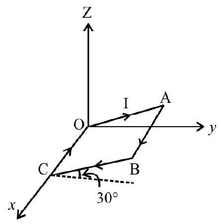
$~$
(1) $(0.07 \hat{j}+0.04 \hat{k}) \mathrm{Am}^{2}$
(2) $(0.04 \hat{\mathrm{j}}+0.07 \hat{\mathrm{k}}) \mathrm{Am}^{2}$
(3) $(0.07 \hat{j}-0.04 \hat{k}) \mathrm{Am}^{2}$
(4) $(0.04 \hat{\mathrm{j}}-0.07 \hat{\mathrm{k}}) \mathrm{Am}^{2}$
Show Answer
Correct Answer: (4)
Solution:
Magnetic moment $\mathbf{M}=\mathrm{I}$. $(\mathbf{O A} \times \mathbf{A B})$
where $\mathbf{O A}=\mathrm{OA} \cos \theta \hat{\mathrm{j}}+\mathrm{OA} \sin \theta \hat{\mathrm{k}}$
$$ \begin{aligned} & \mathbf{A B}=\mathrm{AB} \hat{\mathrm{i}} \\ \therefore \mathbf{M} & =\mathrm{I} \cdot(\mathrm{OA} \cos \theta \hat{\mathrm{j}}+\mathrm{OA} \sin \theta \hat{\mathrm{k}}) \times \mathrm{AB} \hat{\mathrm{i}} \\ & =\mathrm{I} \cdot[\mathrm{OA} \times \mathrm{AB} \cos \theta(-\hat{\mathrm{k}})+\mathrm{OA} \times \mathrm{AB} \sin \theta \hat{\mathrm{j}}] \\ & =4.0\left[200 \times 10^{-4} \cos 30^{0}(-\hat{\mathrm{k}})+200 \times 10^{-4} \sin 30^{\circ} \hat{\mathrm{j}}\right] \\ & =4.0\left[-\sqrt{3} \times 10^{-2} \hat{\mathrm{k}}+10^{-2} \hat{\mathrm{j}}\right] \\ & =10^{-2}[-6.928 \hat{\mathrm{k}}+4 \hat{\mathrm{j}}]=(-0.07 \hat{\mathrm{k}}+0.04 \hat{\mathrm{j}}) \mathrm{Am}^{2} \end{aligned} $$
Hence option (4) is the correct answer.
Difficult
Magnetic Moment
66. A charge ’ $q$ ’ is uniformly distributed on a non-conducting disc, of radius $R$, it is rotated with angular speed ’ $\omega$ ’ about an axis passing through the centre of mass of the disc and perpendicular to its plane. The magnetic moment of the disc will be
(1) $\frac{1}{4} \omega \mathrm{qR}^{2}$
(2) $\frac{1}{2} \omega \mathrm{qR}^{2}$
(3) $\omega \mathrm{qR}^{2}$
(4) $\frac{1}{8} \omega \mathrm{qR}{ }^{2}$
Show Answer
Correct Answer: (1)
Solution:
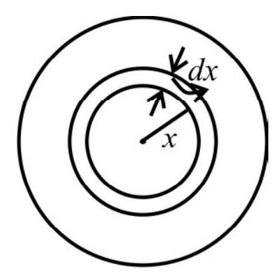
$~$
Consider the disc to be made up of large number of elementary concentric rings, consider one such ring of radius ’ $x$ ’ and thickness ’ $d x$ ‘.
Charge on this ring dq $=\frac{\mathrm{q}}{\pi \mathrm{R}^{2}} \cdot \mathrm{dA}=\frac{\mathrm{q}}{\pi \mathrm{R}^{2}}(2 \pi x \mathrm{~d} x)=\frac{2 \mathrm{q} x \mathrm{~d} x}{\mathrm{R}^{2}}$
Current on this ring $\mathrm{di}=\frac{\mathrm{dq}}{\mathrm{T}}=\frac{\omega \mathrm{dq}}{2 \pi}=\frac{\omega \mathrm{q} x \mathrm{~d} x}{\pi \mathrm{R}^{2}}$
Magnetic moment of this ring $(\mathrm{dM})=\frac{\omega \mathrm{q} x \mathrm{~d} x}{\pi \mathrm{R}^{2}} \pi x^{2}=\frac{\omega \mathrm{q} x^{3} \mathrm{~d} x}{\mathrm{R}^{2}}$
Hence magnetic moment of the entire $\operatorname{disc}(M)=\int d M=\frac{\omega \mathrm{q}}{\mathrm{R}^{2}} \int _{0}^{\mathrm{R}} x^{3} \mathrm{~d} x$
$$ =\frac{1}{4} \omega \mathrm{qR}^{2} $$
Hence option (1) is correct
Difficult
Magnetic Moment
67. A solid conducting sphere, of radius $R$ and total charge $q$, rotates about its diametric axis with a constant angular speed ’ $\omega$ ‘. The equivalent magnetic moment of the sphere is
(1) $\frac{1}{3} \mathrm{qR}^{2} \omega$
(2) $\frac{2}{3} \mathrm{qR}^{2} \omega$
(3) $\frac{1}{5} \mathrm{qR}^{2} \omega$
(4) $\frac{2}{5} \mathrm{qR}^{2} \omega$
Show Answer
Correct Answer: (3)
Solution:
Consider the sphere to be made up of large number of hollow, coaxial cylinder of different height and radii consider one such cylinder of radius ’ $x$ ’ height ’ $y$ ’ and thickness $\mathrm{d} x$.
$\mathrm{y}=2 \mathrm{R} \cos \theta, \quad x=\mathrm{R} \sin \theta, \quad \mathrm{d} x=\mathrm{R} \cos \theta \mathrm{d} \theta$
Charge on this cylinder is $\mathrm{dq}=\frac{\mathrm{q}}{\frac{4}{3} \pi \mathrm{R}^{3}} 2 \pi \mathrm{y} x \mathrm{~d} x$
$ = 3 q \cos^2 \theta \sin \theta d \theta$
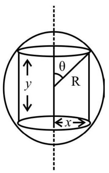 $~$
$~$
Current, associated with this cylinder, is
$$ \mathrm{di}=\frac{\mathrm{dq}}{\mathrm{T}}=\frac{\omega \mathrm{dq}}{2 \pi}=\frac{3 \omega \mathrm{q}}{2 \pi} \cos ^{2} \theta \sin \theta \mathrm{d} \theta $$
Hence magnetic moment associated with this cylinder
$$ \begin{aligned} (\mathrm{dM}) & =\operatorname{di} A=\left[\frac{3 \omega \mathrm{q}}{2 \pi} \cos ^{2} \theta \sin \theta d \theta\right] \pi x^{2} \\ & =\frac{3}{2} \mathrm{R}^{2} \omega \mathrm{qA} \cos ^{2} \theta \sin ^{3} \theta d \theta \end{aligned} $$
Total magnetic moment (M) $M=\int d M=\frac{3}{2} R^{2} q \omega \int _{\pi / 2}^{\theta} \cos ^{2} \theta \sin ^{3} \theta d \theta$
This gives $|\mathrm{M}|=\frac{1}{5} \mathrm{R}^{2} \omega \mathrm{q}$
Average
Magnetic Moment
68. A uniformly charged disc, whose total charge has a magnitude ’ $q$ ‘, and whose radius is ’ $r$ ‘, rotates with a constant angular velocity of magnitude ’ $\omega$ ‘. The magnetic dipole moment of the ring is
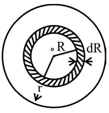 $~$
$~$
(1) $\frac{\mathrm{q} \omega \mathrm{r}^{2}}{4}$
(2) $\frac{q \omega r^{2}}{2}$
(3) $\frac{\mathrm{q} \omega \mathrm{r}^{2}}{8}$
(4) $q \omega r^{2}$
Show Answer
Correct Answer: (1)
Solution:
Surface charge density $=\frac{\mathrm{q}}{\pi \mathrm{r}^{2}}$
$\therefore$ Charge within the ring of radius $\mathrm{R}$ and width $\mathrm{dR}$
$$ \mathrm{dq}=\frac{\mathrm{q}}{\pi \mathrm{r}^{2}}(2 \pi \mathrm{RdR})=\frac{2 \mathrm{q}}{\mathrm{r}^{2}} \mathrm{RdR} $$
Current carried by this ring
$$ \mathrm{di}=\frac{\mathrm{dq}}{\mathrm{T}}=\frac{\omega \mathrm{dq}}{2 \pi}=\frac{\mathrm{q} \omega}{\pi \mathrm{r}^{2}} \mathrm{RdR} $$
Hence magnetic moment contributed by this ring $(\mathrm{dM}) \mathrm{di} \times$ Area $=\frac{\mathrm{q} \omega}{\pi \mathrm{r}^{2}} \mathrm{R} d \mathrm{R} \times \pi \mathrm{R}^{2}$
$$ =\frac{\mathrm{q} \omega}{\mathrm{r}^{2}} \mathrm{R}^{3} \mathrm{dR} $$
Total magnetic moment of the ring
$M=d M=\int _{0}^{r} \frac{q \omega}{r^{2}} R^{3} d R=\frac{q \omega}{r^{2}}\left(\frac{R^{4}}{4}\right) _{0}^{r}=\frac{q \omega r^{2}}{4}$
Hence option (1) is correct
Average
Cyclotron
69. The (angular) frequency, $\omega$, of the alternating p.d applied across the dees, and the strength, $B$, of the (normal) magnetic field, used, in a given cyclotron, have been adjusted to values (say $\omega _{0}$ and $B _{0}$ ), that would enable this cyclotron to accelerate protons.
If the same cyclotron were to be used for accelerating alpha particles, say, the new value of (i) $\omega$, when $B$ is left unchanged at its earlier value $\left(B _{0}\right.$ ) and (ii) $B$, when $\omega$ is left unchanged at its earlier value $\left(\omega _{0}\right)$, would equal, respectively
(1) $\frac{\omega _{0}}{2}$ and $\frac{\mathrm{B} _{0}}{2}$
(2) $\frac{\omega _{0}}{2}$ and $2 \mathrm{~B} _{0}$
(3) $2 \mathrm{~B} _{0}$ and $\frac{\omega _{0}}{2}$
(4) $2 \omega _{0}$ and $2 \mathrm{~B} _{0}$
Show Answer
Correct Answer: (2)
Solution:
The radius of the circular path, of the charged particle, in a magnetic field, is given by $\frac{\mathrm{mv}^{2}}{\mathrm{r}}=\mathrm{qvB}$
Hence $\mathrm{r}=\frac{\mathrm{mv}}{\mathrm{qB}}$
The time period, for one cycle of the motion of the charged particle, in this circular path, is given by
$$ \mathrm{T}=\frac{2 \pi \mathrm{r}}{\mathrm{v}}=\frac{2 \pi \mathrm{mv}}{\mathrm{v} \cdot \mathrm{qB}}=\frac{2 \pi \mathrm{m}}{\mathrm{qB}} $$
The corresponding angular frequency, $\omega$, equals $\frac{2 \pi}{\mathrm{T}}=\frac{\mathrm{qB}}{\mathrm{m}}$
In the adjusted cyclotron, the (angular) frequency of the applied alternating potential equals this (cyclotron) frequency.
Hence for the protons, we have $\omega _{0}=\frac{\mathrm{eB} _{0}}{\mathrm{~m}}$
For the $\alpha$-particle, the required (angular) frequency, say, $\omega _{\alpha}$, is given by
$$ \omega _{\alpha}=\frac{(2 \mathrm{e}) \mathrm{B} _{\alpha}}{(4 \mathrm{~m})}=\frac{\mathrm{eB}}{2 \mathrm{~m}} $$
(i) When there is no change in the value of $\mathrm{B}$, we would have $\omega _{\alpha}=\frac{\mathrm{eB}}{\mathrm{m}} \times \frac{1}{2}=\frac{\omega _{0}}{2}$
(ii) When there is no change in the value of $\omega _{0}$, we would have $\omega _{0}=\frac{\mathrm{eB}}{2 \mathrm{~m}}$
$$ \text { or } \quad \frac{\mathrm{eB} _{0}}{\mathrm{~m}}=\frac{\mathrm{eB} _{\alpha}}{2 \mathrm{~m}} \quad\left(\therefore \mathrm{B} _{\alpha}=2 \mathrm{~B} _{0}\right) $$
Hence option(2) is correct
Difficult
Cyclotron
70. A cyclotron’s oscillation frequency is $10 \mathrm{MHz}$. If the radius of its dee is $60 \mathrm{~cm}$ than the kinetic energy of the proton beam, accelerated by the cyclotron is $\left(\mathrm{e}=\mathbf{1 . 6 \times 1 0 ^ { - 1 9 }} \mathrm{e}, \mathrm{m} _{\mathrm{p}}=1.67 \mathrm{x}^{-27}\right)$.
(1) $7.5 \times 10^{3} \mathrm{MeV}$
(2) $7.5 \mathrm{MeV}$
(3) $3.75 \mathrm{MeV}$
(4) $7.5 \mathrm{keV}$
Show Answer
Correct Answer: (2)
Solution:
The charged particles orbit round the circular path, with a frequency, $f$, given by $f=\frac{B e}{2 \pi m}$
Hence $B=\frac{2 \pi \mathrm{mf}}{\mathrm{e}}$
Substituting the given values, we get, $\mathrm{B}=0.66 \mathrm{~T}$
The period of revolution of the particles, is $\mathrm{T}=\frac{2 \pi \mathrm{m}}{\mathrm{Be}}$
If $R$ is the radius of the dee’s of the cyclotron, than the velocity $v$ of the protons, at the point of exit, is
$$ \mathrm{v}=\frac{2 \pi \mathrm{R}}{\mathrm{T}}=\frac{2 \pi \mathrm{R} \times \mathrm{Be}}{2 \pi \mathrm{m}}=\frac{\mathrm{BeR}}{\mathrm{m}} $$
Kinetic energy of the protons produced is $\frac{1}{2} \mathrm{mv}^{2}=\frac{\mathrm{B}^{2} \mathrm{e}^{2} \mathrm{R}^{2}}{2 \mathrm{~m}}=7.5 \mathrm{MeV}$
Hence option(2) is correct
Easy
Tessestral Magnetism
71. Angle of dip at a place is $30^{\circ}$. If the verticle component of earth’s magnetic field at that place is $(0.16 \sqrt{3}) \times 10^{-4} \mathrm{~T}$, the value of the horizontal component would be
(1) $48 \times 10^{-4} \mathrm{~T}$
(2) $0.048 \times 10^{-4} \mathrm{~T}$
(3) $144 \times 10^{-4} \mathrm{~T}$
(4) $ 0.48 \times 10^{-4} \mathrm{~T}$
Show Answer
Correct Answer: (4)
Solution:
We know than $\delta=\frac{\mathrm{B} _{\mathrm{V}}}{\mathrm{B} _{\mathrm{H}}}$
Hence $\mathrm{B} _{\mathrm{H}}=\left(\frac{\mathrm{B} _{\mathrm{V}}}{\tan \delta}\right)$
$\therefore \quad \mathrm{B} _{\mathrm{H}}=\frac{(0.16 \times \sqrt{3}) \times 10^{-4}}{\tan 30^{0}}=\frac{(0.16 \times \sqrt{3}) \times 10^{-4}}{\left(\frac{1}{\sqrt{3}}\right)} \mathrm{T}=0.48 \times 10^{-4} \mathrm{~T}$
Hence option(4) is correct
Easy
Terrestrial Magnetism
72. At the magnetic poles, earth’s total magnetic field is
(1) Perpendicular to surface of the earth
(2) Parallel to the surface of the earth
(3) zero
(4) will be at a dip of $60^{\circ}$
Show Answer
Solution:
Denoting by $\mathrm{B}, \mathrm{B} _{\mathrm{H}}$ and $\mathrm{B} _{\mathrm{v}}$, the total feild of earth, horizontal component of earth’s field and vertical component of earth’s field, we have
$ \mathrm{B} _{\mathrm{V}}=\mathrm{B} \sin \delta $
where $\delta$ is the angle of dip.
At magnetic poles $\delta=90^{\circ}$ and hence $\mathrm{B} _{\mathrm{H}}=0$
At the poles, the earth’s totoal field is, therefore, the same as its vertical component. It is, therefore, perpendicular to the surface of earth at the poles.
Hence option(1) is correct
Easy
Terrestrial Magnetism
73. If we represent earth’s magnetic field at the equator, by $B$, the dipole moment of earth (radius $=\mathbf{R}$ )’s equivalent magnet is given by
(1) $\frac{4 \pi R^{3} B}{\mu _{0}}$
(2) $\frac{4 \pi R^{2} \mathrm{~B}}{\mu _{0}}$
(3) $\frac{2 \pi \mathrm{RB}^{2}}{\mu _{0}}$
(4) $\frac{2 \pi R B}{\mu _{0}}$
Show Answer
Correct Answer: (1)
Solution:
We can assume earths magnetic field as due to a (short) bar magnet, centered at the centre of earth and held along its polar axis. We can then write:
$$ \mathrm{B} _{\text {equator }}=\frac{\mu _{0} \mathrm{M}}{4 \pi \mathrm{R}^{3}} $$
where $\mathrm{M}$ is the dipole moment of earth’s equivalent magnet.
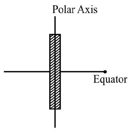
$~$
Hence $\mathrm{M}=\frac{4 \pi \mathrm{R}^{3} \mathrm{~B}}{\mu _{0}}$
Hence option(1) is correct
Average
Terrestrial Magnetism
74. For a partical plane, other than the magnetic meridian, i.e., a vertical plane at some angle $\theta$, with the magnetic meridian,
(1) angle of dip decreases
(2) angle of dip increases
(3) angle of dip remain uneffected
(4) the apparent value of the angle of dip becomes zero
Show Answer
Correct Answer: (2)
Solution:
For a vertical plane at an angle $\theta$ with the magnetic meridian.
$$ \mathrm{B} _{\mathrm{H}}^{\prime}=\mathrm{B} _{\mathrm{H}} \cos \theta \quad \text { and } \quad \mathrm{B} _{\mathrm{V}}^{\prime}=\mathrm{B} _{\mathrm{V}} $$
Therefore, observed angle of dip $\delta$, in a vertical plane, making an angle $\theta$, with the magnetic meridian, would be
$$ \begin{aligned} & \tan \delta^{\prime}=\frac{\mathrm{B} _{\mathrm{V}}^{\prime}}{\mathrm{B} _{\mathrm{H}}^{\prime}}=\frac{\mathrm{B} _{\mathrm{V}}}{\mathrm{B} _{\mathrm{H}} \cos \theta}=\frac{\tan \delta}{\cos \theta} \quad\left(\because \frac{\mathrm{B} _{\mathrm{V}}}{\mathrm{B} _{\mathrm{H}}}=\tan \delta\right) \\ & \therefore \tan \delta^{\prime} =\frac{\tan \delta}{\cos \theta} \end{aligned} $$
Here $\delta$ represents the true value of dip and $\delta^{\prime}$ is the apparent value of dip.
For a vertical plane other than magnetic meridian,
$\theta>0^{0}$ and $\cos \theta<1$
$\therefore \quad \delta^{\prime}>\delta$
Hence the angle of dip : increases
Hence option(2) is correct
Average
Terrestrial Magnetism
75. At a certain location a compass points $15^{\circ}$ west of geographic north. The north tip of the magnetic needle, of a dip circle placed in the plane of the magnetic meridian, points $60^{\circ}$ above the horizontal. If the horizontal component of earth’s magnetic field is measured to be $0.2 \mathrm{G}$, the magnitude and direction of the earth’s field at that location, are
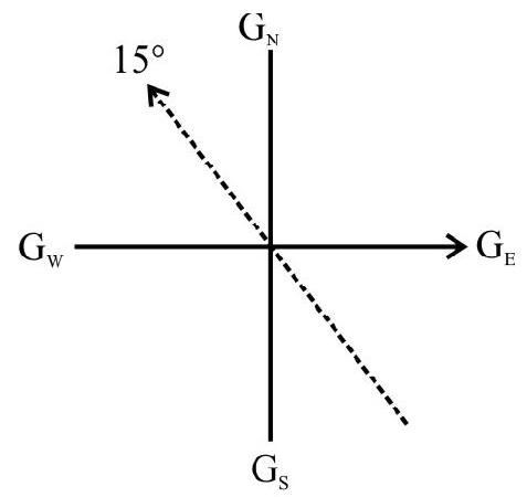
$~$
(1) $0.4 \mathrm{G}$, directed upward of the horizontal line, in the vertical plane, $15^{\circ}$ west of geographic north plane
(2) $0.4 \mathrm{G}$, directed downward of the horizontal line, in the vertical plane, $15^{\circ}$ west of geographic north plane
(3) $0.4 \mathrm{G}$, directed upward of the horizontal line, in the vertical plane, $15^{\circ}$ east of geographic north plane
(4) $0.4 \mathrm{G}$, directed downward of the horizontal line, in the vertical plane, $15^{\circ}$ east of geographic north plane
Show Answer
Correct Answer: (1)
Solution:
We have $\mathrm{B} _{\mathrm{H}}=\mathrm{B} \cos \delta$
$\therefore \quad B=\frac{B _{H}}{\cos \delta}=\frac{0.2}{\cos 60} \mathrm{~T}=\frac{0.2}{0.5} \mathrm{~T}=0.4 \mathrm{~T}$
As shown by the compass needle, B points upward of the horizontal line, $15^{\circ}$ west of geographic north plane.
Hence option(1) is correct
Average
Terrestrial Magnetism
76. A ship is to reach a place $7^{\circ}$ south of west. If the declination of the plane at the place is $15^{\circ}$ of north west the ship should be steered along
(1) east of magnetic north at an angle of $82^{\circ}$
(2) west of magnetic south at an angle of $82^{\circ}$
(3) west of magnetic north at an angle of $82^{\circ}$
(4) west of magnetic north at an angle of $115^{\circ}$
Show Answer
Correct Answer: (3)
Solution:
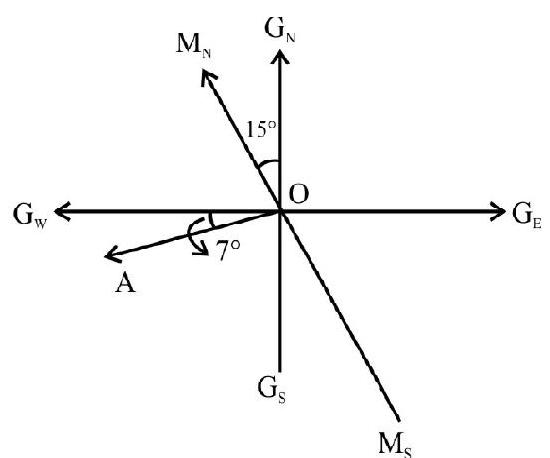
$~$
As the ship is to read $7^{0}$ at a place south of west along $0 \mathrm{~A}$ ), it should be steered west of magnetic north at an angle of $\left(\frac{\pi}{2}-15^{0}+7^{0}\right)=82^{0}$
Hence option(3) is correct
Average
Elements of Earth’s Magnetic Field
77. The angle of dip, and the horizontal component of earth’s magnetic field, at a given place, equal $\alpha$ and $B _{H}$, respectiely. If a charged particle, of charge $q$ and mass $m$, were to move with a speed $v$, horizontally northwards at that place, the magnitude of the acceleration, caused on this charged particle, would equal
(1) $\frac{q _{v B} \cot \alpha}{m}$
(2) $\frac{\mathrm{qvB} _{\mathrm{H}} \cos \alpha}{\mathrm{m}}$
(3) $\frac{q v B _{H} \tan \alpha}{m}$
(4) $\frac{q^{2} B _{H} \sin \alpha}{m}$
Show Answer
Solution:
Since the charged particle is moving horizontally north wards, it would experience a force, only due to the vertical component (say $\mathrm{B} _{\mathrm{v}}$ ) of the earth’s (total) magnetic field (= B say). The angle of dip being $\alpha$, we can write
$$ \begin{array}{r} \mathrm{B} _{\mathrm{H}}=\mathrm{B} \cos \alpha \text { and } \mathrm{B} _{\mathrm{V}}=\mathrm{B} \sin \alpha \\ \therefore \quad \frac{\mathrm{B} _{\mathrm{V}}}{\mathrm{B} _{\mathrm{H}}}=\tan \alpha \quad \text { or } \quad \mathrm{B} _{\mathrm{V}}=\mathrm{B} _{\mathrm{H}} \tan \alpha \end{array} $$
The force, due to the earth’s magnetic field, on the charged particle, has a magnitude F, where
$$ \mathrm{F}=|\mathrm{q}(\mathbf{v} \times \mathbf{B})|=\mathrm{qvB} _{\mathrm{v}} $$
$\therefore$ The acceleration caused, has a magnitude
$$ \mathrm{a}=\frac{\mathrm{F}}{\mathrm{m}}=\frac{\mathrm{qvB} _{\mathrm{v}}}{\mathrm{m}}=\frac{\mathrm{qvB} _{\mathrm{H}} \tan \alpha}{\mathrm{m}} $$
Hence option(4) is correct
Difficult
Classification of Magnetic Materials
78. An iron rod (of density $8 \times 10^{3} \mathrm{~kg} / \mathrm{m}^{3}$ and specific heat capacity $0.462 \times 10^{-3} \mathrm{~J} / \mathrm{kg}^{0} \mathrm{C}$ ) is subjected to cycles of magnetissation at the rate of $50 \mathrm{cycles} / \mathrm{s}$. If the area enclosed by B.H curve corresponds to an energy of $10^{-2}$ joule, the rise of temperature per minute (assuming there are no radiation losses) would be
(1) $81^{\circ} \mathrm{C}$
(2) $8.1^{\circ} \mathrm{C}$
(3) $0.81^{\circ} \mathrm{C}$
(4) $16.2^{\circ} \mathrm{C}$
Show Answer
Correct Answer: (2)
Solution:
The area enclosed by the $\mathrm{B}-\mathrm{H}$ curve, equals the energy loss per unit volume per cycle.
$\therefore$ The energy loss per unit volume in one second $=10^{-2} \times 50 \mathrm{~J}$
Hence $Q$, the heat produced per unit volume in one minute, equals
$$ \mathrm{Q}=\left(10^{-2} \times 50 \times 60\right) \mathrm{J}=30 \mathrm{~J} $$
Let $\theta$ be the rise in temperature per unit volume. The mass per unit volume equals $\rho$, the density. Hence
$$ \mathrm{Q}=\rho \mathrm{s} \theta $$
Hence $8 \times 10^{3} \times 0.462 \times 10^{-3} \times \theta=30$
or $\quad \theta=\frac{30}{0.462 \times 8}{ }^{0} \mathrm{C}=8.1^{\circ} \mathrm{C}$
Hence option(2) is correct
Difficult
Classification of Magnetic Materials
79. An iron rod $0.2 \mathrm{~m}$ long, $10 \mathrm{~mm}$ in diameter and of permeability $10^{3}$, is placed inside a long solenoid wound with $300 \mathrm{turns} / \mathrm{meter}$. If a current of $0.5 \mathrm{~A}$ is passed through the rod, total magnetic moment of the rod would be (nearly)
(1) 2335 SI Unit
(2) 233.5 SI Unit
(3) 23.35 SI Unit
(4) 2.335 SI Unit
Show Answer
Correct Answer: (4)
Solution:
$\mathbf{M}$, the magnetisation vector (magnetic moment per unit volume is given by)
$ \mathbf{M}=\left(\frac{\mathbf{B}}{\mu _{0}}\right)-\mathbf{H}=\frac{\mu \mathbf{H}}{\mu _{0}}-\mathbf{H}=\left(\mu _{\mathrm{r}}-1\right) \mathbf{H} $
$\therefore \quad \mathbf{M}=\left(\mu _{\mathrm{r}}-1\right) \mathbf{H}$
For a long soleniod $|\mathbf{H}|$ is given by
$ \begin{aligned} & |\mathbf{H}|=\mathrm{ni}=300 \times 0.5 \text { SI Units }=150 \text { SI Units } \\ & \therefore|\mathbf{M}|=(1000-1) \times 150 \simeq 0.15 \times 10^{6} \text { SI Unit } \end{aligned} $
Total magnetic moment of rod $=|\mathbf{M}| \times \mathrm{V}=\mathrm{M} \times \pi \mathrm{r}^{2} \mathrm{~L}$
$ =0.15 \times 10^{6} \times 3.142 \times\left(5 \times 10^{-3}\right)^{2} \times 0.2 $
$\approx 2.335$ SI units
Hence option (4) is correct
Difficult
Terrestrial Magnetism
80. Let $\delta _{1}$ and $\delta _{2}$ be the angle fo dip in any two vertical planes (other than the magnetic meridian) that are at right angles to each other. If, $\delta$ is the true value of the angle of dip, we would have
(1) $\tan ^{2} \delta _{1}+\tan ^{2} \delta _{2}=\tan ^{2} \delta$
(2) $\frac{\tan ^{2} \delta _{1}}{\tan ^{2} \delta _{2}}=\cot ^{2} \delta$
(3) $\cot ^{2} \delta _{1}+\cot ^{2} \delta _{2}=1$
(4) $\cot ^{2} \delta=\cot ^{2} \delta _{1}+\cot ^{2} \delta _{2}$
Show Answer
Correct Answer: (4)
Solution:
Let the vertical plane, in which angle of dip is $\delta _{1}$ subtends an angle $\theta$ with the magnetic meridian. Their other plane then subteneds an angle $\left(\frac{\pi}{2}-\theta\right)$ with the magnetic meridian.
We have, $\tan \delta=\frac{\mathrm{B} _{\mathrm{V} _{1}}}{\mathrm{~B} _{\mathrm{H} _{1}}}=\frac{\mathrm{B} _{\mathrm{V}}}{\mathrm{B} _{\mathrm{H}} \cos \theta}$
$\therefore \quad \cot \delta _{1}=\frac{\mathrm{B} _{\mathrm{H}} \cos \theta}{\mathrm{B} _{\mathrm{V}}}$
Similarly $\cot \delta _{2}=B _{H} \frac{\cos \left(\frac{\pi}{2}-\theta\right)}{B _{V}}=\left(\frac{B _{H} \sin \theta}{B _{V}}\right)$
Hence $\cot ^{2} \delta _{1}+\cot ^{2} \delta _{2}=\left(\frac{\mathrm{B} _{\mathrm{H}}}{\mathrm{B} _{\mathrm{V}}}\right)^{2}\left(\cos ^{2} \theta+\sin ^{2} \theta\right)$
$ =\left(\frac{\mathrm{B} _{\mathrm{H}}}{\mathrm{B} _{\mathrm{V}}}\right)^{2} \times 1=\cot ^{2} \delta \quad\left(\because \frac{\mathrm{B} _{\mathrm{V}}}{\mathrm{B} _{\mathrm{H}}}=\tan \delta\right) $
Hence, $\cos ^{2} \delta=\cot ^{2} \delta _{1}+\cot ^{2} \delta _{2}$
Hence option(4) is correct


