UNIT 12 CURRENT ELECTRICITY
Learning Objectives
After going through this, unit you will be able to understand, appreciate and apply the following concepts:
- Electrical energy from different type of the cells.
- Meaning of emf and the essential difference between emf and terminal potential difference.
- Current and sign convention for the current.
- Drift velocity and the physics of the Ohm’s law.
- Concept of resistance and its variation will temeperature.
- Combination of resistance in series and parallel.
- Joule’s law and the concept of electrical power.
- Kirchoff’s laws for circuit analysis.
- Wheatstone bridge: its practical form the meter bridge.
- The principle and applications of potentiometer.

Electric Current
It is a well known fact that the electron is an atomic particle carrying a negative charge. Electrons can be detached from the atoms of certain elements quite easily. If we connect a conductor to something which supply or absorb charge as required to maintain a applied electric field (cells, batteris etc.), this maintained field than can act on the free electrons in the conductor and will give them a resultant motion in a direction opposite to that of the field. Charges in motion constitute an electric current. If a net charge q passes through any cross section of the conductor in time
When equals quantities of charge
In general the rate of flow of charge with time is not constant and the current varies with time. It is then given by differential limit viz.
The current
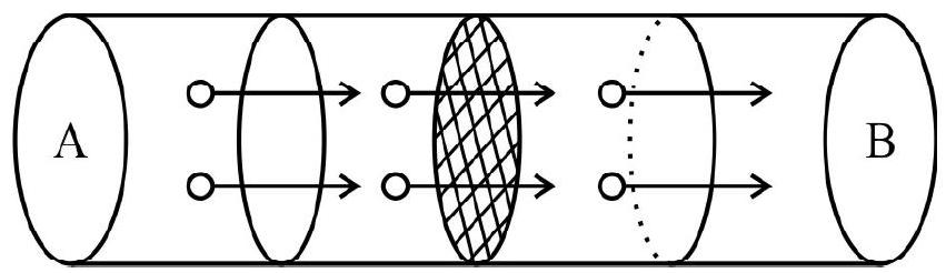
Figure shows a portion of a wire in which there is a field towards the left and consequently the motion of the free electron towards the right. Let the electrons move with a constant drift velocity
Hence the current
The Direction of a Current
A logic way to define the direction of a current is the direction of motion of free electrons. However in electrolytic and gaseous conduction, the current is due to the motion of positive and negative ions. Historically the sign convention for the current was defined taking positive charge carriers as current carriers. Since these would be a incosistancy whether we define a sign convention taking positive or negative particles as charge carriers we continue to work with historical sign convention. In conductors the free electrons move in the opposite direction to the conventional current. If required we can label the current flowing in a conductor due to the motion of free electrons as Electronic Current.
Resistance: Proper understanding of resistance is possible only through Ohm’s law. Qualitatively speaking resistance of a material is a measure of its ability to resist the flow of electricity through it.
Ohm’s Law
Verified experimentally Ohm’s law states that the current flowing through a conductor is proportional to the voltage
The constant
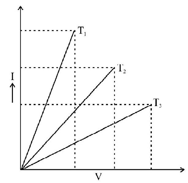
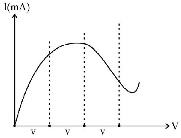
Ohm’s law, a experimental law is valid only for metallic conduction. We now know that there are quite a number of substances (e.g. semi conductors) for which Ohm’s law is not always valid. For such cases the current voltage graphs are not linear. We illustrate this piont by showing the plot of current voltage graph for some interesting cases:


Electrical Resistivity
The resistance of a conductor depends on the nature of its material, its shape and size, Simple consideration show that the resistance of wires of a given length increases in direct proportion to their length and for wires of a given area of cross section the resistance increases in inverse proportion of their area of cross section.
We thus have,
or
Colour Code for Resistances
Resistances are an integral path of practically all electrical and electronic circuits. The values of resistances needed in different circuits very over a wide range and for convenience a colour code has been developed.
The colour code works as follows:
1. We associate a colour with each digit
| Colour | Black | Brown | Red | Orange | Yellow | Green | Blue | Violet | Gray | White |
|---|---|---|---|---|---|---|---|---|---|---|
| Associated Digit | 0 | 1 | 2 | 3 | 4 | 5 | 6 | 7 | 8 | 9 |
2. There are three colour bands on each resistance to indicate its value. The first two bands from one end indicate their corresponds digits while the third band colour gives the power of ten with which
the number obtained by first two colours must be multiplied to get the resistance value in ohm. For example if a resistance has three colours as yellow, orange and blue, the resistance value is
3. In addition to the above colours, two additional colours - SILVER and GOLD are also used. When used as fourth colours band they indicate the TOLERANCE or percentage realibility in the value of the resistanc obtained.
A silver band implies a tolerance of
4. Silver band used as the third band indicate a multiplier value of
Physics of the Oh’m Law
Ohm’s law relate the current flowing in a conductor with the potential difference across its ends. We know that current is a flow of free elctrons under a maintained field. This could imply that free clarges in a conductor should continuously get accelerated which imply that the current should go on increasing with time. However only a stready current governed by Ohm’s law flows. This implies that in a conductor, a constant electric field produces a constant velocity, a contradication of Newton’s second law. Let us try to understand the reason for this observed behaviour.
We note that an electric field exerts a force
Now the electrons in a metal at any temperature are, by themselves, moving will fairly high velocities that are randomly distributed. Hence the average velocity of any free electron in the direction of the field, at the instant the field is switched on is zero. The field imports the electron an acceleration in its own direction
where
However this acceleration lasts but for a short time as the electron on its way encounters the metal ions that are vibrating about their mean position. Since the magnitude and direction of these ions vibration at the instant of collision can have arbitrary value, they will produce a random deflection in the path of the electron when it undergoes a collision with one of these. On the average these random collisions of the free electron may occur after a time
This additional velocity imparted by the field to a freely and otherwise randamly moving electron is known its DRIFT velocity. After the collision the electron may again be deflected in any random direction so that as we can assume that the (average) distribution of free electtron velocities after a time
If there are
Putting,
which is Ohm’s Law
Effect of Temperature on Resistance
We have seen that the resistivity
1. The extent of randomness in the arragement of ionic and atomic sites on the lattice of the given material.
2. The temperature of the given substance.
An increase in temperature will cause the ions and atomc to vibrate with a greater amplitude about their mean position and will increase the frequency of collisions. Hence a rise in temperature cause
For quite a few substances, the increase in resistively with temperature is a linear one and we may write a relation of the form.
where we define
However the variation of resistivity with temperature is not linear for all type of substances. Even for metals, the resistivity increases as a higher power of
For insulationis and semi conductors, the resistivity increases exponentially with decreasing temperature, the variation being expressed by a relation of the form.
Here
It follows that the resistivity of insulators and semi-conductors becomes very large at low temperatures tending to infinite large values at
Super Conductors
The property of metals of getting currents flow through them without practically any opposition as
Super conductors are finding many interesting applications in technology. Some of the prominent applications include.
1. Super conductor electric power transmission lines with no power loss due to heating may soon become a possiblity.
2. Super conductors may be used to product very high speed computers.
3. Powerful magnets made with superconducting coils are being used.
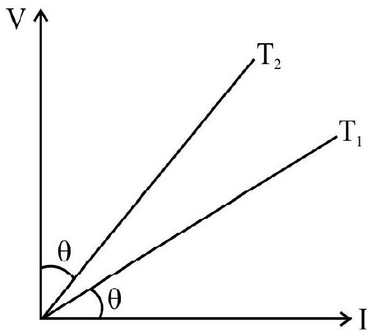
Example-1
Show Answer
Solution:
The slope of a
Hence
Since the slope of the graph corresponding to
Resistance in Series and Parallel
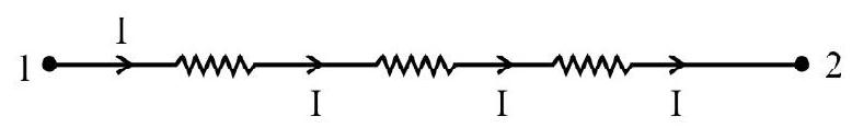
Sereis Arrangment: When two or more resistance are joined in such a way that the second end of the first resistance is connected to the first and of the second resistance and so on as shown the resistance are said to be connected in series.
In series arrangment the current flowing through all the resistance is the same. Thus
Also voltage drops are added and their summation would equal to total voltage output.
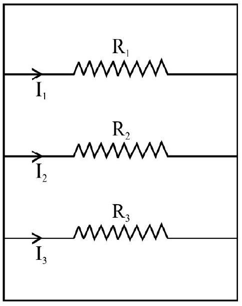
Parallel Arragnment: When two or more resistances and joined in such way that the first ends of all are connected to one common point and second ends of all connected to a second common point, the resistance are said to be joined in parallel.
In parallel arrangment the same current should leave the end 2 as enter at the end 1.
Hence
The voltage that impresses itself on the side 1 of each resistor has be the same. Since the voltage must equalize itself all branches on the left side of parallel arrangement.
Now,
or
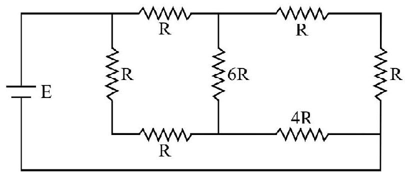
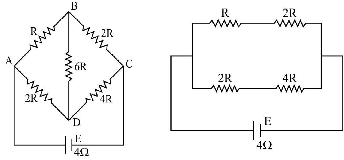
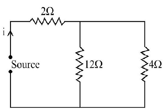
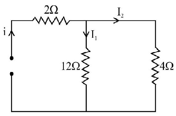
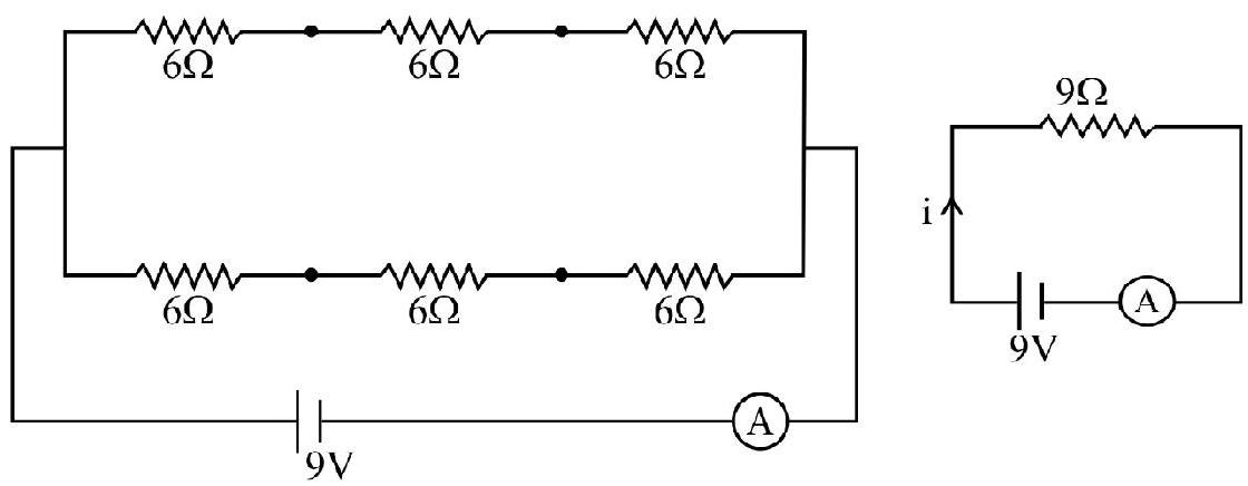
Example-2
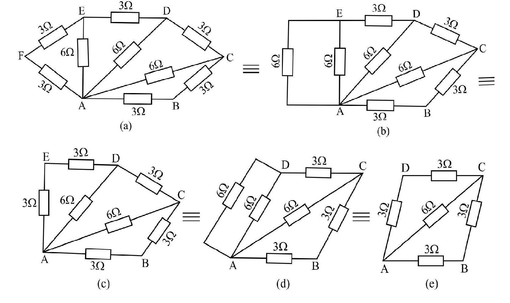
Determine the equivalent resistance of the following networks.

Show Answer
Solution :
We can regard the network of Figure (a) as a series combination of four resistances in the form of network as shown
This can further be simplified as shown.
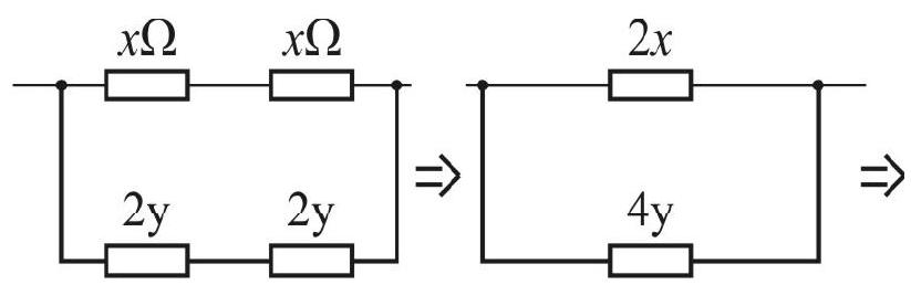

It is clear that the effective resistance of this networks is
Hence the total effective resistance of the given network is given by:
The network of figure (b) is simply a series combination of 5 resistances each of value
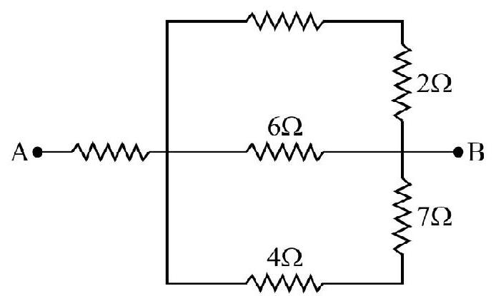
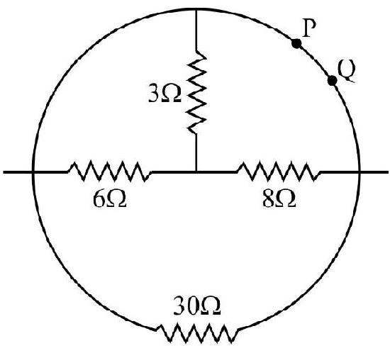
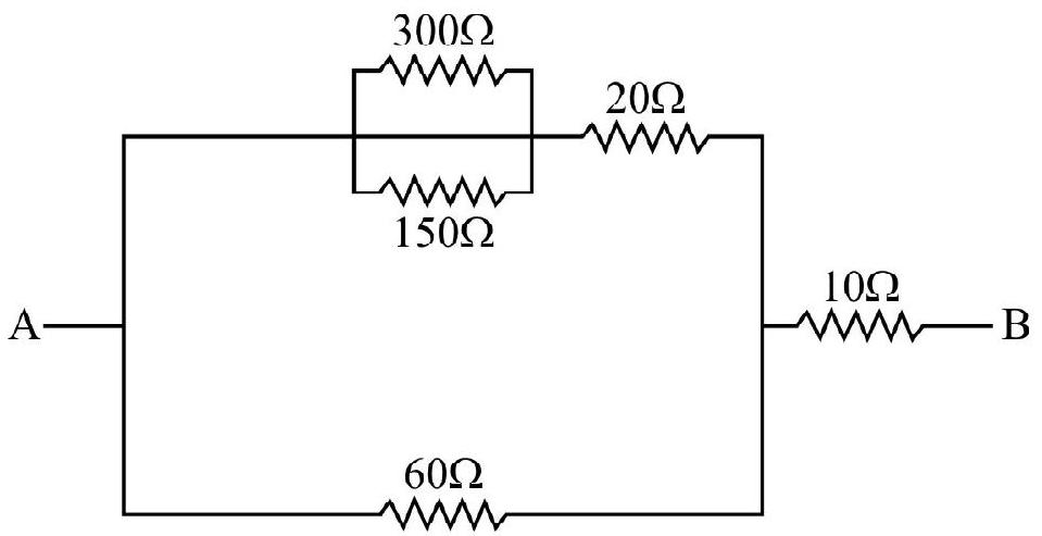
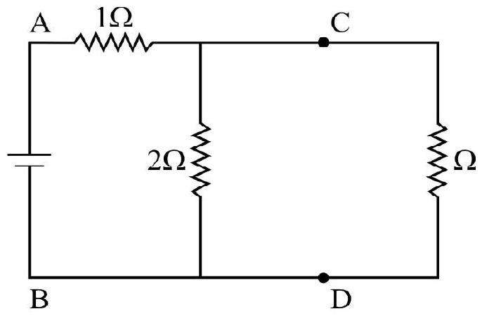
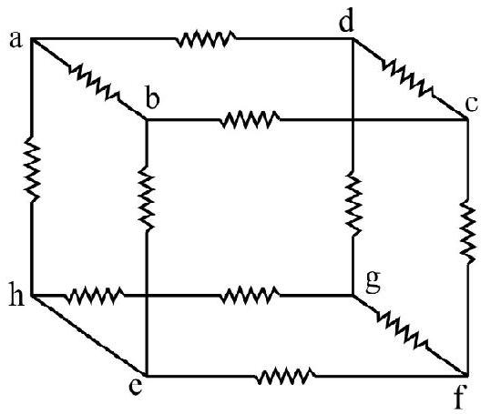
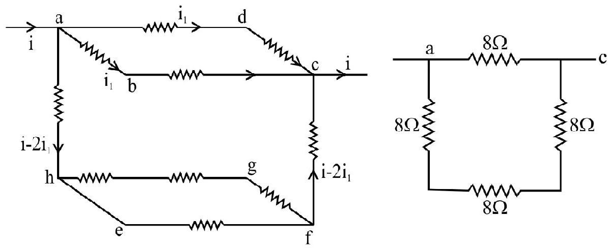
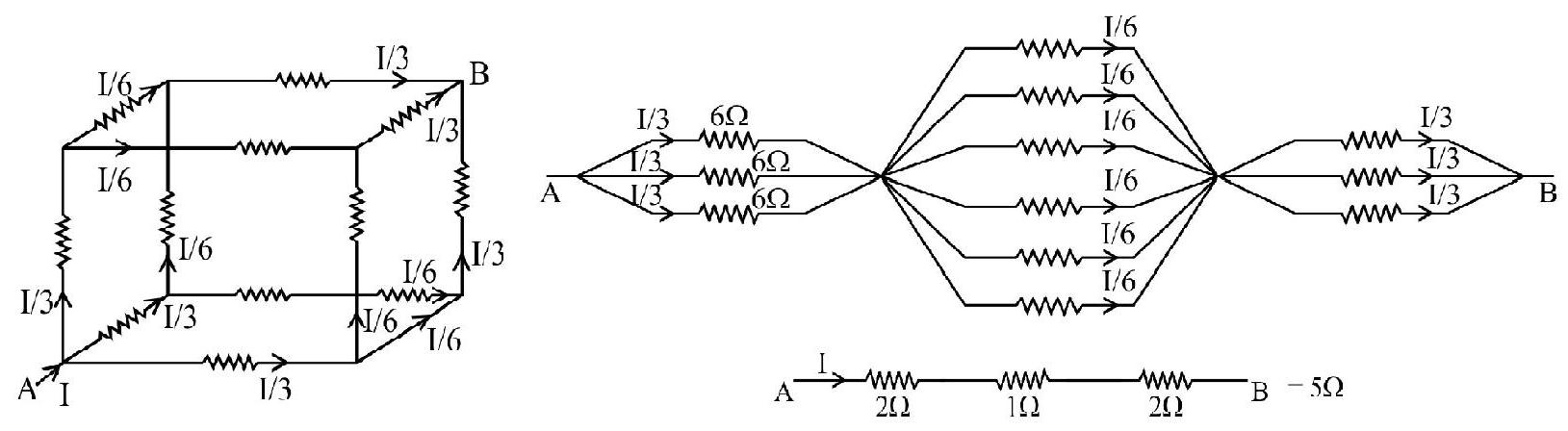
Example-3
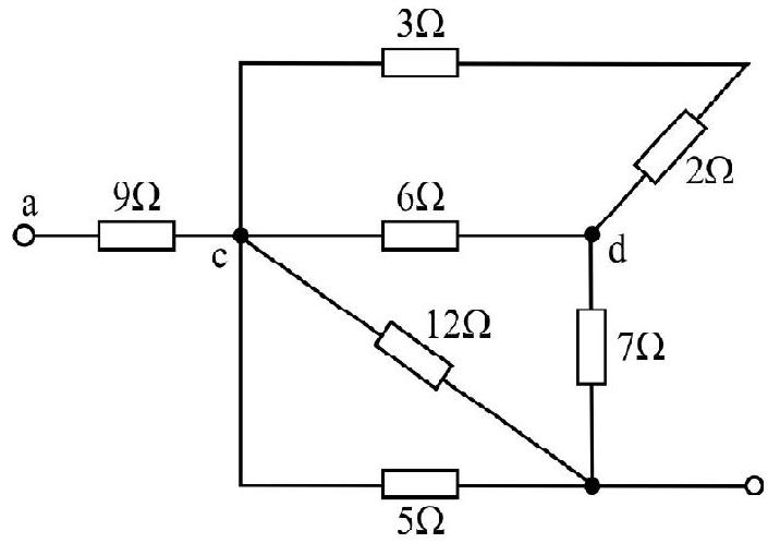
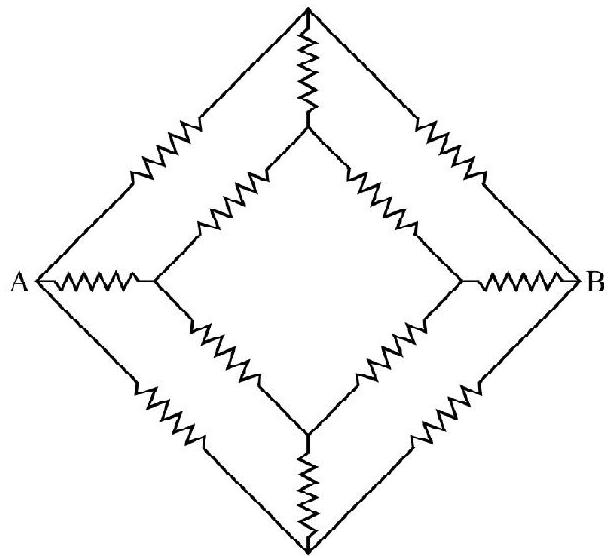
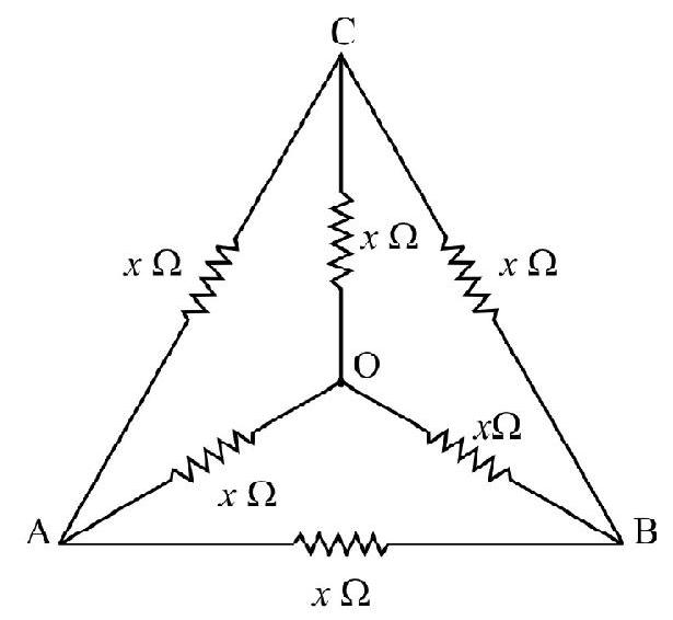
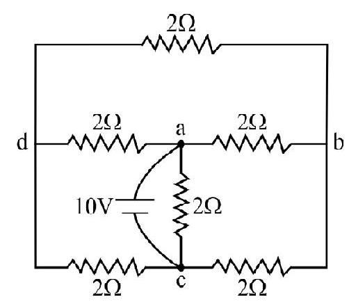
Find the equivalent resistance between points
Show Answer
Solution :
The
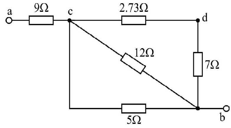
The
Now
Let their equivalent be R". The
Finally
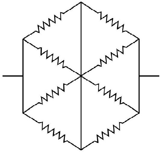
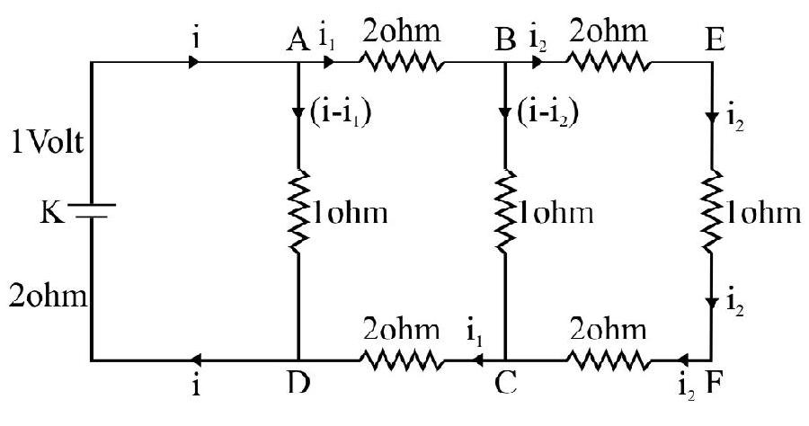
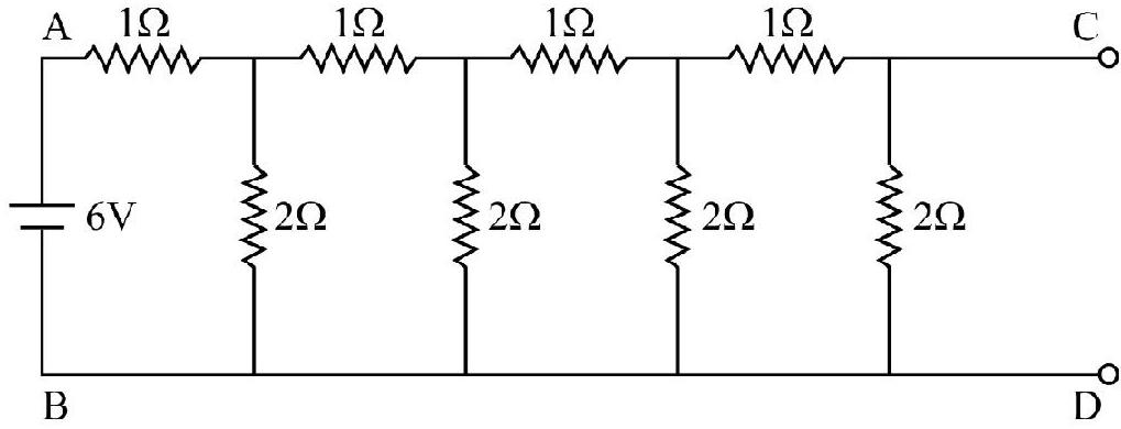
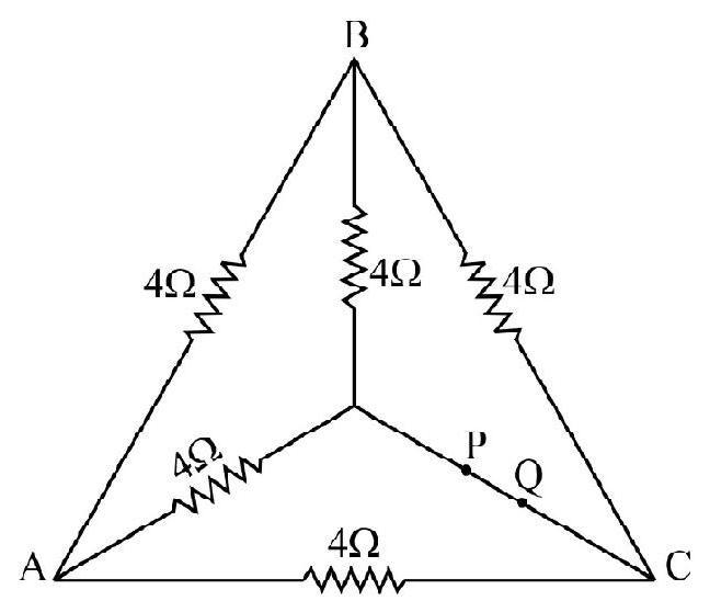
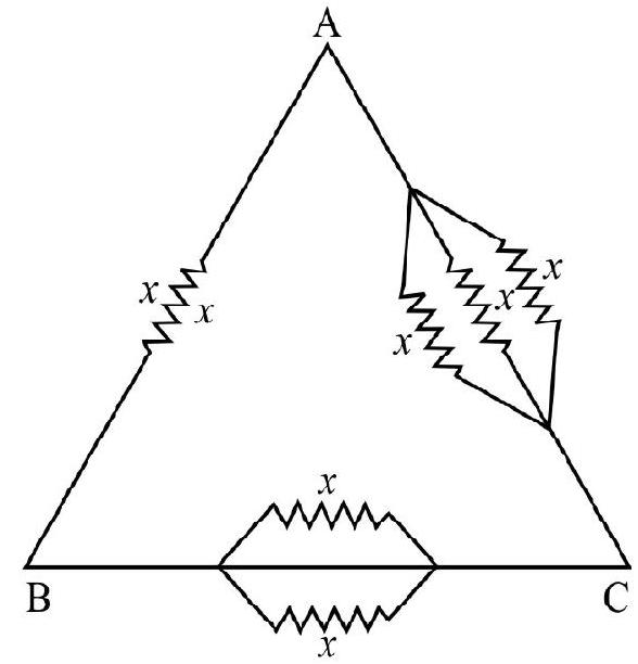
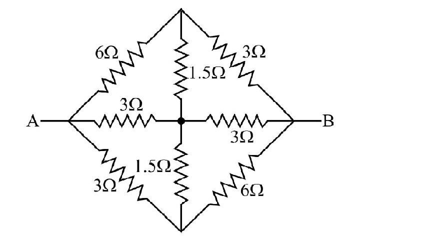
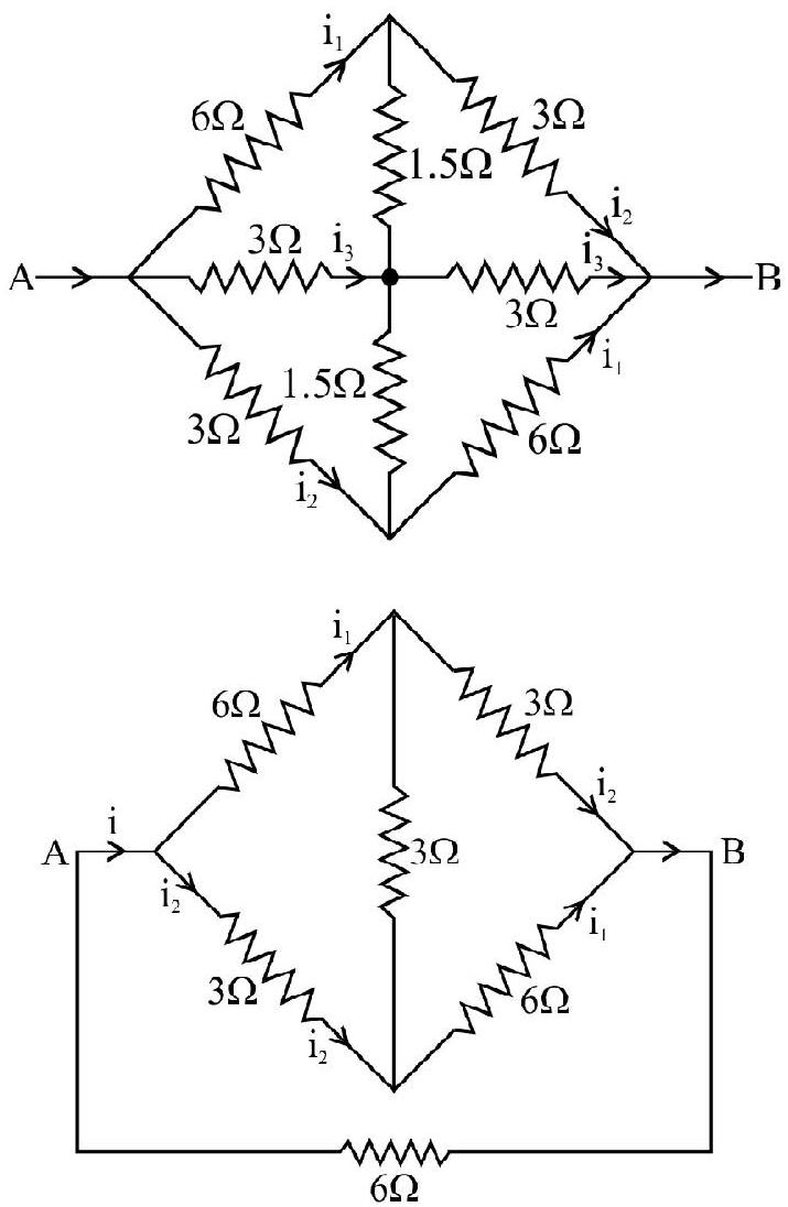
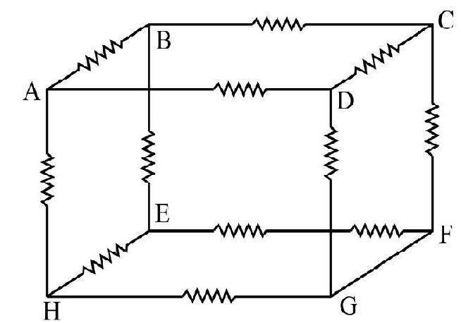
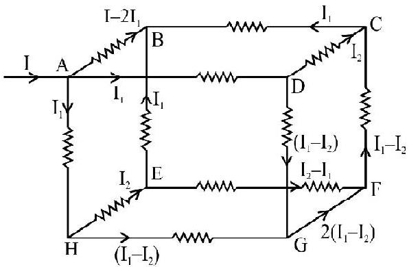
Example-4
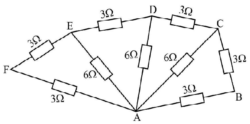
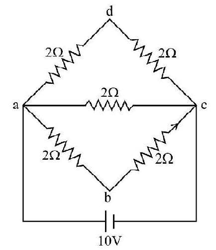
Find the effective resistance between points
Show Answer
Solution :
Figure shows successive reduction of the circuit.
It is clear from figure that the effective resistance between points
Electric Cell
The simplest device to maintain a current in an electric circuit is the electrolytic cell. In this type of cell the chemical energy of a reaction is converted into electrical energy. The electrods in a simple volticcell are copper and zinc with dilute sulphuric acid as electrolyte. The action of a simple voltate cell can be understood as follows. At the zinc electrode
The simple voltic cell has two main defects viz (s) local action and polarization.
Daniel cell, Leclance cell and Dry cells are example of Primary cells.
Lead accumulator and alkali accumlator are exmaples of Secondary cells.
We can now directly convert the energy of light into electrical energy by using solar cells. The action of solar cells depend on proparties of semiconducting materials.
In nuclear cells the energy of
e.m.f. of a Cell
We know that electrostatic field is conservative in nature i.e.
Hence electrostatic field by itself is incapable of esatablishing a current in a closed circuit. It follows that for the maintanance of current in a closed circuit a non conservative field force that can spend energy is a basic necessity.
Any source which can produce such a force is called a source of electromotive force. The electric force due to chemical ractions in a battery is an example of a non conservative field that is used for maintaining current.
Considering a battery as an example, we know that chemical energy is converted into electrical energy by chemical reactions taking place in it. The generation of energy provides the non conservative field which we assume to be directed from
The battery e.m.f. is defined as
Here the line integral between
Internal resistance of a cell is defined as the resistance offered by the electrolyte and electrode of a cell when a electric current flows through it.
Terminal Potential Differnece
When a current is drawn from a cell there is a drop of potential across the internal resistance of the cell (equal to ir) where as e.m.f. of a cell is the maximum potential difference between two electrodes of a cell. when current is drawn from the cell.
Hence terminal potential difference is between two electrodes of a cell in a closed circuit.
Thus, it is clear
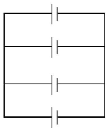
Grouping of Cells
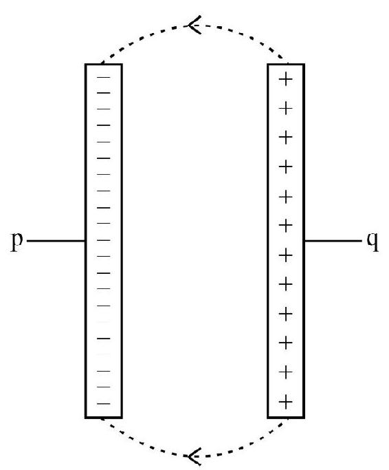
Cells can be connected in series as shown. When
Then
The equivalent e.m.fof a series combinations
The equivalent internal resistance of a series combination of
and
We can also have a mixed grouping of cells (say
Now there are
Hence,
Since the parallel combination of rows of cells does not effect the e.m.f. of each row of cells therfore the effective e.m.f. of all cells is
The condition for
Heating Effect of Curretn (Joule Heat)
We know that in a circuit certaining resistors the flow of current electric result in the production of heat energy. We have already discussed that the metallic conduction is due to free electrons. These free electrons frequently collide with the atoms of metal in lattice. At each collision they lose some of their kinetic energy and give it to the atoms they strike. Thus as the current flows through a wire it increases the kinetic energy of we vibrations of metal atoms and hence it generates heat in the wire, the energy lost per second by the electrons is the electrical power supplied by the battery which maintains the current. Considering a circuit as shown in figure, experimentally we observe the following facts:
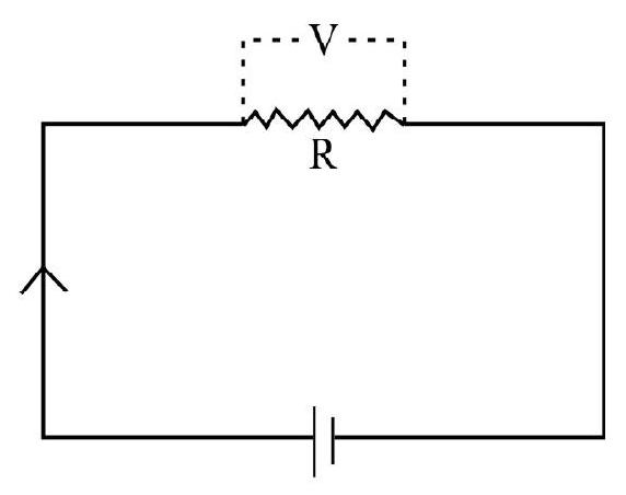
1. The heat produced is proportional to the square of current.
2. The heat produced is proportional to resistance.
3. The heat produced is proportional to the time for which current flows.
Thus, we can write
Electrical Power
The energy liberated per second in an electrical device is called electric power.
When an electric current flows through a wire or ‘passive resistance’ all the power which it conveys to the wire appears as heat. If I is he current
as
Example-5
An immersion heater which is to operate on
Show Answer
Solution :
Mass of water
Rise of temperature
Heat used
Efficiency of operation
Total heat produced
Heat produced in one hour
Now wattage
or
Example-6
A series bettery of 10 accumulation each of emf
Show Answer
Solution :
Let
Let,
Energy stored in 2 Hour
Kirchoff’s Laws
Electrical circuits contains simple arrangment of resistances in series or parallel and with a known source of e.m.f. can be analysed in a straightward manner using Ohm’s law. In many important cases we encounter networks where there may be junctions between two or more conductors at which current can flow along various paths and where one or more sources e.m.f. may be active. In such cases we solve the circuits by making use of Kirchoff’s law. To apply these law we define two terms.
1. A branch point is a point of the circuit where three or more conductors are joined together.
2. A loop is any closed conducting path in the network.
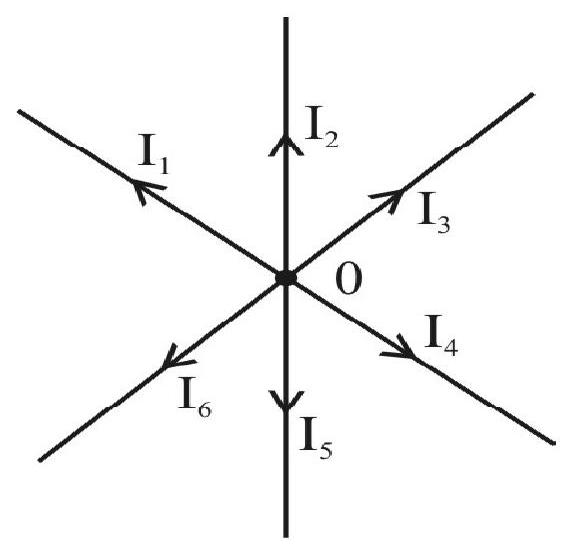
First Law
The algebraic sum of the currents flowing toward a branch point is zero. The convention for sign is.
The current flowing toward a branch point is considered positive whereas a current flowing away from a branch point is considred negative. For example in the figure shown we have:
Second Law
The algebraic sum of the emf’s in any loop of the network is euqal to algebraic sum of IR drops in it i.e.
To apply the loop equation we must take some direction either clockwise or anticlockwise as the traversal direction. An emf is taken with positive sign if the emf by itself produce a positive current in the sense of traversal direction. Similarly we take an IR turn with the positive sign if the current through the resistor in question is in the direction of the traversal.
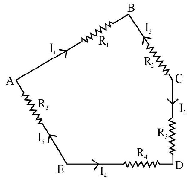
For example in the figure shown taking
To solve the networks will the help of Kirchoff’s law we proceed stepwise as follows:
(a) We assign currents with assumed directions to every branch in the network. There direction should be indicated in the circuit diagram. Then making use of Kirchoff’s first law we reduce the number of unknowns as far as possible.
(b) We next write down the voltage equations using Kirchoff’s second law to conveniently choosen loops. There must be the same number of independent equation as are the unknown.
(c) Finally we solve these equations to obtain unknown quantities.
We illustrate the use of Kirchoff’s law by taking the case of a Wheatstone bridge. The circuit diagram is shown in figure. Suppose we want to calculate Ig. Let the currents in all the branches be as indicated. Applying Kirchoff’s fisst law we have
at
Applying Kirchoff’s second law to mesh ABDA weget
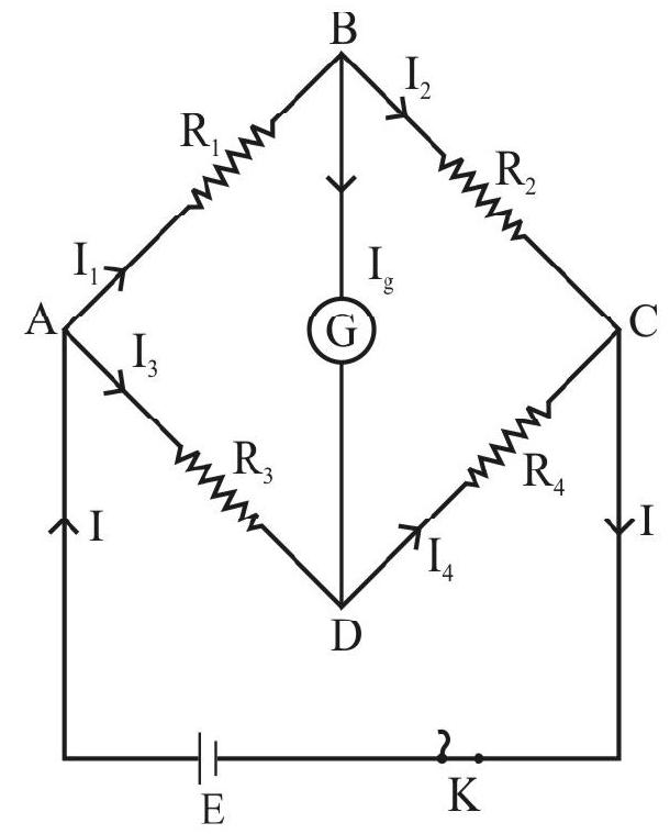
For mesh BCDB we have
or
or
We eliminate
Solving we get,
Condition for balance would be obtained by putting
This gives
We can also obatin this condition by putting
The above equation an IDEAL condition. This is because
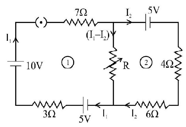
Example-7
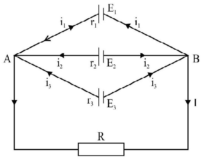
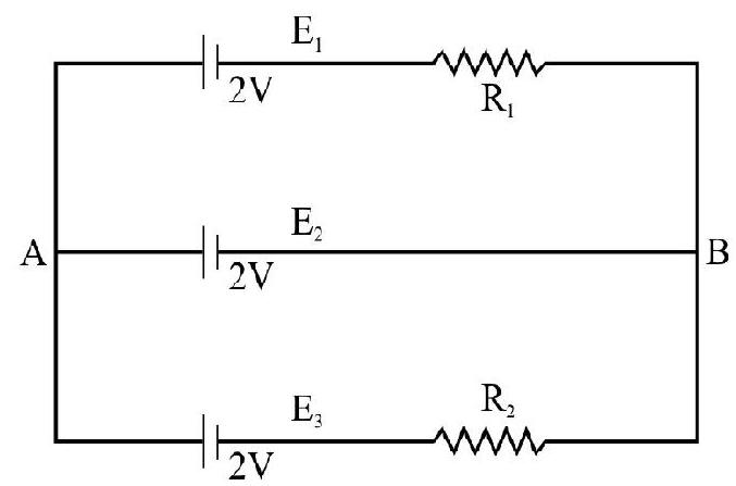
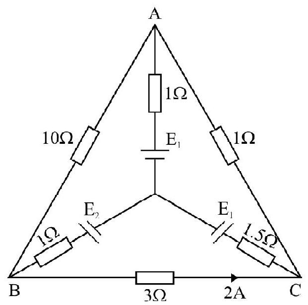
Three cells of emf’s
Show Answer
Solution :
Suppose
Applying second law to the mesh
Similarly,
and
Divides equation (2) by
or
or
Similar expression for
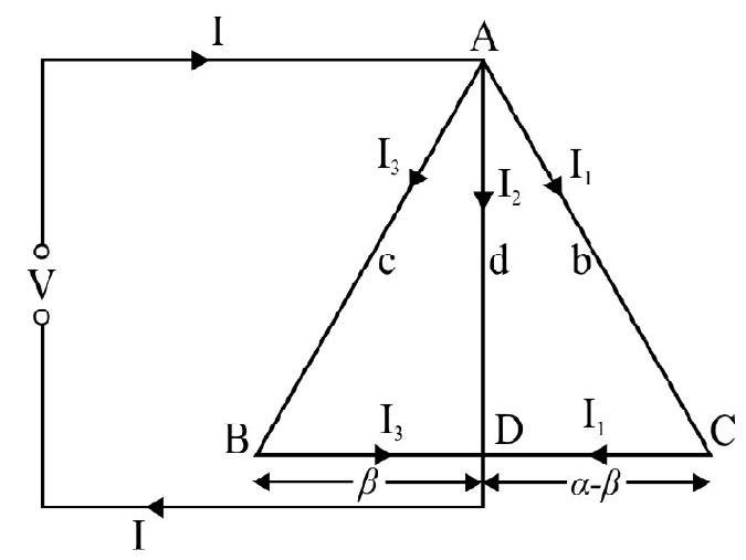
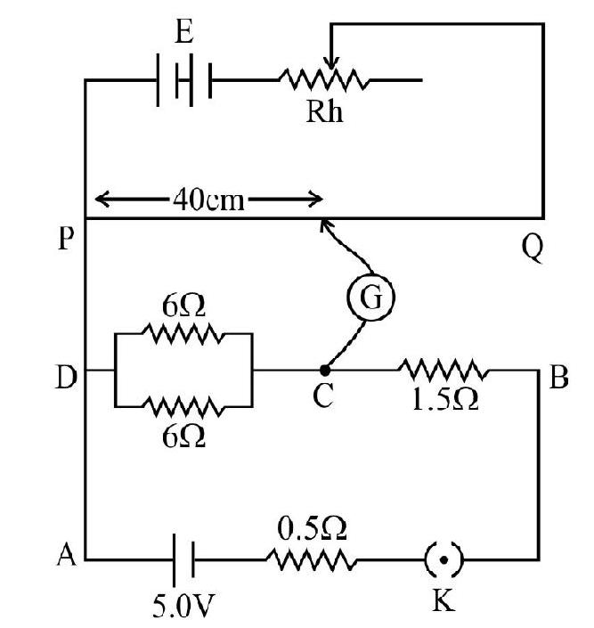
Example-8
The resistance of three wires
Show Answer
Solution :
Let the sliding were make contact with wire
We have for network ADVA
For network ABDA
or
Similarly for network ACDA
If
Hence combining we get,
For maximum value of
or
or
For
or
Substituting the value of
Hence,
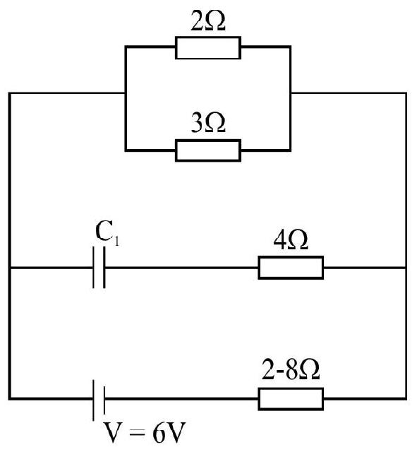
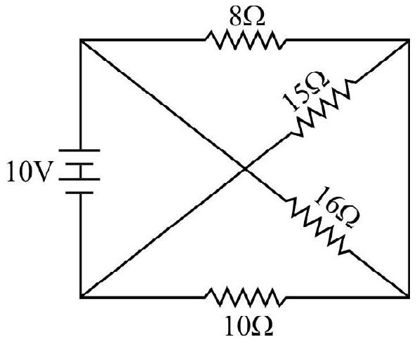
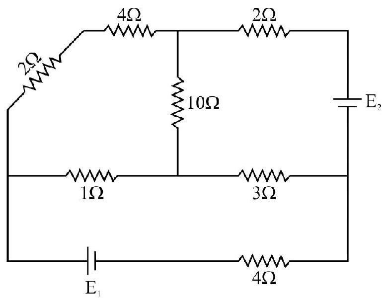
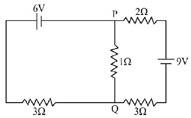
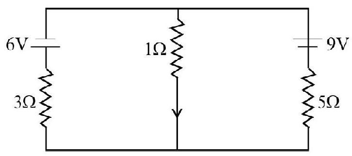
Exmaple-9 :
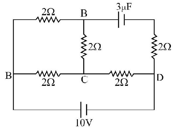
Calculate the steady stage current in the
Show Answer
Solution :
The current distribution in the various arms of the network is shown in figure It is important to note the capacitor
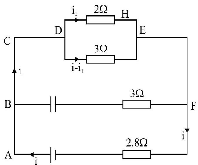
From loop ABCD H EFGA
From loop DHEJD
From (1) and (2) we have,
Metre Bridge
A meter bridge is a pratical application of a Wheatstone bridge. It consists of a straight and uniform wire one meter long. The internal wire has a high resistivity and low temperature co-efficient of resistance (Manganin is the material used).
The wire is stretched along a meter scale with its ends soldered to two copper strips of neglible resistance between the copper strips and third one fixed along the panel have two gaps
The unknown resistance is connected in the gap
The position of jockey is adjusted until the galvanometer shows no deflection. Since the wire is of uniform thickness, the resistance is proportional to length.
Let
Then we have,
The determination here may be inaccurate due to the following errors:
(a) Non uniformaty of the wire. To eliminate this error the metar bridge wire must be calibrated in an auxillary experiment.
A program to guve wingst on th stdents
(b) The position of the point where the jockey makes contact with the wire may not be shown accurately by the pointer attached to the scale.
This error may be eliminated by interchanging
(c) The ends of the wire may not coincide will the ends of the scale and there may be a small resistance where the wire is connected to the copper strip. This resistance is known as END correction. To determine we take
Now interchanging the positions of
Solving these two equations for
(d) If a current is passed for a longer direction of time the point may flicker. To avoid this the current in the wire may be kept as small as possible and the key should be pressed for as short a time as possible while taking a reading.
Example-10
Two parallel resistance
Show Answer
Solution :
S is the combination of parallel combination of
or
Let the balance point be at a distance of
Solving for
Potentiometer
The potentiometer is a very useful instrument which can be used to measure a unknown e.m.f.
The principle of a potentiometer can be understodd by referring to figure.
Here
Let us consider the wire
Given a choice, we would prefer to use a ten wire potentlometer over a four wire potentiometer for a better accuracy of measurement (
Usually one find various faults in potentiometer circuit. We discuss below various possibilties:
(a)
(b)
The reason for this fault is that the accumlator that drives the current through the potentiometer produces too small a p.d. across the wire. To eliminate this error we must either recharge the accumulator or if there is a resistance in series with the wire this must be reduced.
(c)
(d)
(e)
There is a loose connection some where in the circuit.
A potentiometer is a very verstile instrument and can be used for:
(i) Comparison of emf’s of two cells.
(ii) Determination of internal resistance of a cell.
(iii) Determination of a low resistance.
(iv) Measurement of current.
(v) Measurement of high emf.
(vi) Measurement a very low e.m.f. (thermocouple)
Comparision of e.m.f. of Two Cells
Connect point 1 of the two way key and obtain a balance point at a length
Where
Now connect contact 2 of the two way key and obtain a balance point at a length
Hence,
Determination of Internal Resistance of a Cell
The circuit arrangment is shown in the figure. E is the cell whose internal resistance ir is to be measured A resistance box
By adjusting the rheostat
Then
Where
Now key K is closed with a known resistance R out of resistance box. Once again without disturbing rheostat
Let I be the current drawn throught the cell by resistance
Also,
Sovling we get,
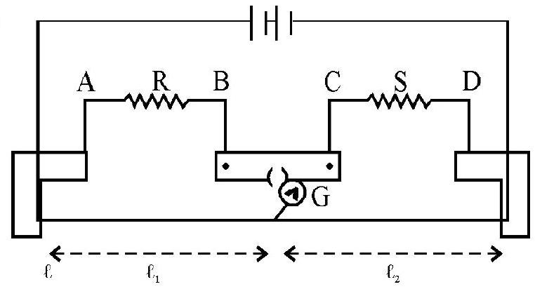
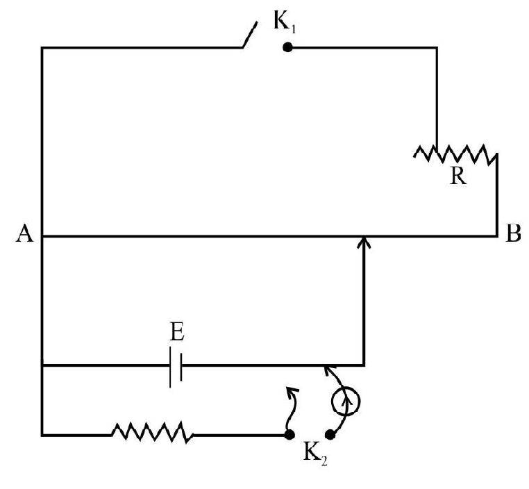
Example-11
The circuit shown in figure is designed to measure an unknown. Resistance using a potentiometer. When there is no deflection
Show Answer
Solution :
We have,
and
Hence,
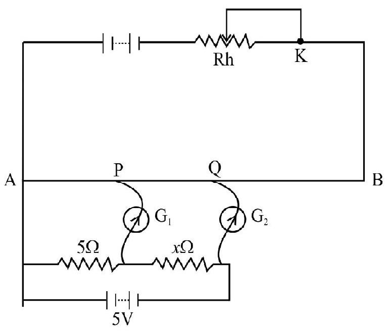
Example-12
A potentiometer (with potential gradient
Show Answer
Solution :
When the key between 1 and 2 is plugged in
When the key between 1 and 3 is plugged in coil
PROBLEMS FOR PRACTICE
1. The resistivity of the material of a wire is
Show Answer
Answer:2. Acarbon resistor of
Show Answer
Answer: Violet, yellow and orange3. Two wires of equal length one of aluminum and the other of copper have the same resistance. Which of the two is lighter?
Relative density of
Show Answer
Answer: Aluminium4. A wire with a resistance of
Show Answer
Answer:5. At what temeperature would the resistance of a copper conductor be double its resistance at
Show Answer
Answer:6. An iron wire
Show Answer
Answer:7. A heater connected to a
Show Answer
Answer:8. A transmission line
Coefficient of linear expansion
Temperature coefficient
Density at
Resistively at
Show Answer
Answer: -80 or 1209. Calculate the equivalent resistance between
Show Answer
Answer:10. Find the equivalent resistance between
Show Answer
Answer:11. Find the effective resistance between points
Show Answer
Answer:12. Calculate the equivalent resistance between point
Show Answer
Answer:13. Find the equivalent resistance between
Show Answer
Answer:14. Twelve resistance each of value
Show Answer
Answer:15. Four identical cells each of e.m.f. E are connected in parallel providing supply of current to external circuit consisting of two resistances of resistance
Show Answer
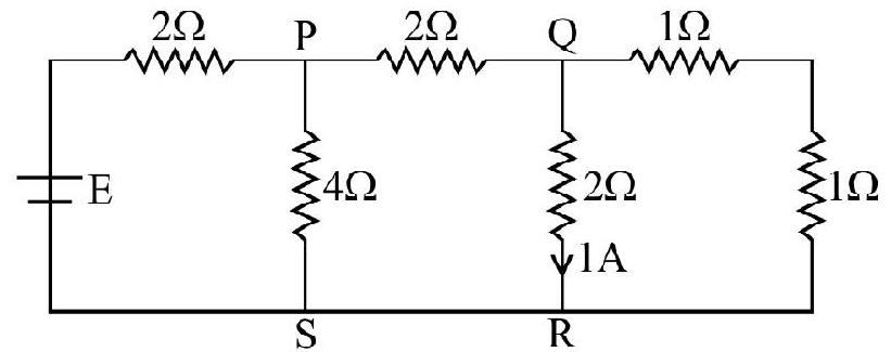
Answer:16. In the circuit shown, calculate the current flowing between
Show Answer
Answer:17. In an electric furnace
Given,
Specific heat of tin
Melting point of tin
Latent heat of fusion of
Thermal efficienty
Show Answer
Answer:18. What is the wattage and voltage ratings of a bulb which will produce maximum brightness when connected across a battery of e.m.f.
Show Answer
Answer:19. Two bulbs rated
Show Answer
Answer: In series:20. A lead fuse in a circuit consisting of a copper wire with cross sectional area
Show Answer
Answer:21. Ahigh speed lift weighing
Show Answer
Answer:22.
Show Answer
Answer:23. An electric current of 5A is divided into three branches, the lenghts of the wires in three branches are proportional to 1,2 and 3.Find the current in each branch. The wires are of the same material and cross section.
Show Answer
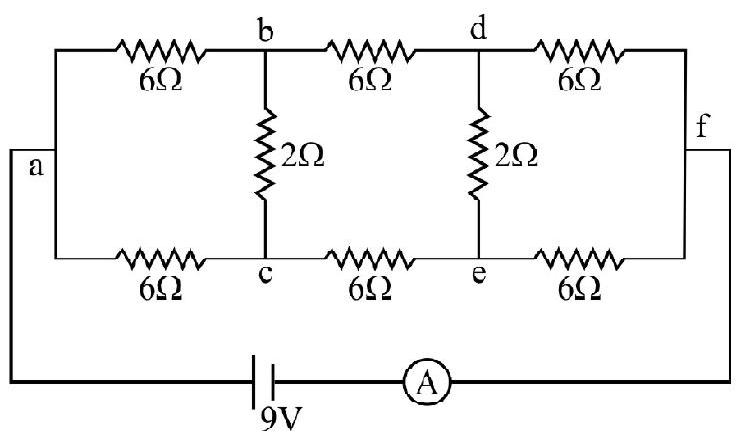
Answer:24. In the circuit shown in figure, what is the current through
Show Answer
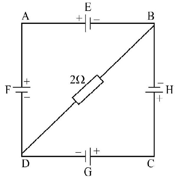
Answer:25. Two squares
A cell of e.m.f. 2 volt and internal resistance
Show Answer
Answer:
26. In the circuit shown in figure
(i) The potential difference between
(ii) The potential difference across the terminals of the cells
Show Answer
Answer:27. In the circuit shown in figure, the current through
resistance.
What is the value of
Show Answer
Answer:28. Twelve equal wires each of resistance
Show Answer
Answer:29. A letter is constructed of a uniform wire of resistance
Show Answer
Answer:30. In a meter bridge, the balance point is found to be at
Show Answer
Answer:31. The resistance of a meter bridge wire is
Show Answer
Answer:32. A resistance of
Show Answer
Answer:33.
Show Answer
Answer:34. The resistance of a potentiometer wire is
Show Answer
Answer:35. A potentiometer wire of length
Show Answer
Answer:36. In an experiemnt with a potentiometer to measure the internal resistance of a cell when the secondary circuit is shunted by
Show Answer
Answer:37. A
Show Answer
Answer:38. A potentiometer circuit using a standard cell of emf 1.02 volt is setup as shown in Figure If the balancing length with 1,3 connection is
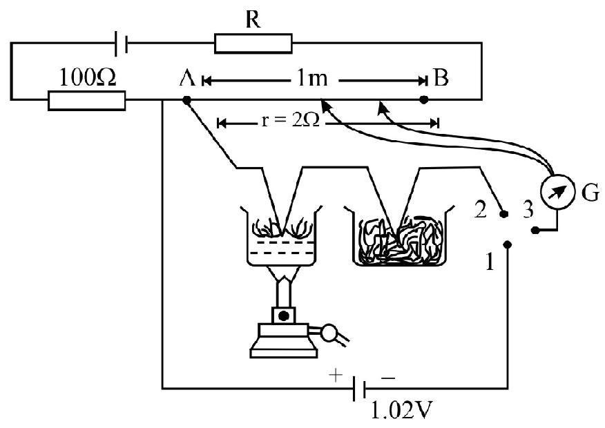
Show Answer
Answer:Question Bank
Key Learning Points
1. The free electrons in a conducter in a maintained electric field constitute a current.
2. The electric field that acts on the electrons in a conductor does not produce a net acceleration because the electrons keep on colliding with the ctoons leat make up the conductor and thereby acquire a constant drift velocity
Where
3. The general expression for the current is
where
4. The same current flows through the every cross section of the conductor even of its is not uniform.
5. According to ohm’s law the current is directly proportional to the potational difference provided the physical conditions of the conductor remains unchanged.
i.e.
Where
6. The resistance of any conductor can be expressed in terms of the length
Where
7. The equivalnce resistance of resistance
(i) In series, is
(ii) In parallel, is
8. The variation of resistance with temperature is given by
where
9. The resistance of metals increases with temperature. However for semi conductor and insulators resistivity increases exponnentally with decreasing temperature.
10. Super conductors (metals like
11. For solving complicated network use is made of Kirchoff’s laws.
12. Wheatstone bridge is a special type of resistance network for measuring the resistance (It cannot be used for measurement of very low and very high resistances). The condition of balance is:
13. A Wheatstone bridge has optimum sensitivity when the resistance in its all branches are of the same order of magnitude.
14. A cell is a device in which by means of chemical reactions, chemical energy is converted into electrical energy. A cell provides the necessary potential difference for maintaining a current in an electric circuit.
15. Emf a cell is the potential difference between its terminal when the cell does not draw any current (open circuit) whereas the terminal potential difference is defined as the potential difference between its terminal in a closed circuit.
The two are related as:
where
16. When a number of cells of emf’s
(i) In series, then,
(ii) In parallel, then,
and
17. Meter bridge is based on the Wheatstone bridge and is used to measure resistance.
Referring to figure we have,
For better accuracy we have to take into account end corrections.
18. Potentiometer is a verstile instrument. Here we balance an unknown e.m.f.
(i) To compare two emf’s
(ii) To determine the internal resistance of a cell
(iii) Measurements of current.
(iv) Measurement of high emf.
(v) Measurement of a very small emf.
19. If a current of I ampere traverses a conductor between the ends of which there is a potential difference equal to
Average
Combination of Cells
1. N identical cells, each of emf
Show Answer
Correct Answer: (2)
Solution:
Ifn cells, of e.m.f.
and
From these equations we have,
and
Hence option (2) is correct.
Average
Terminal p.d
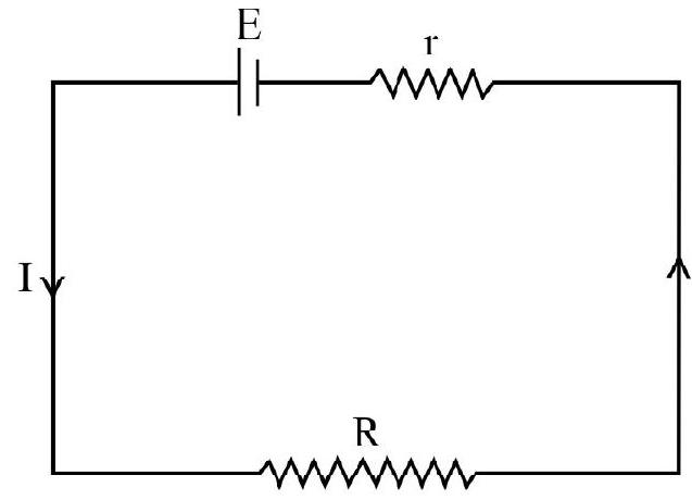
2. A cell having an emf
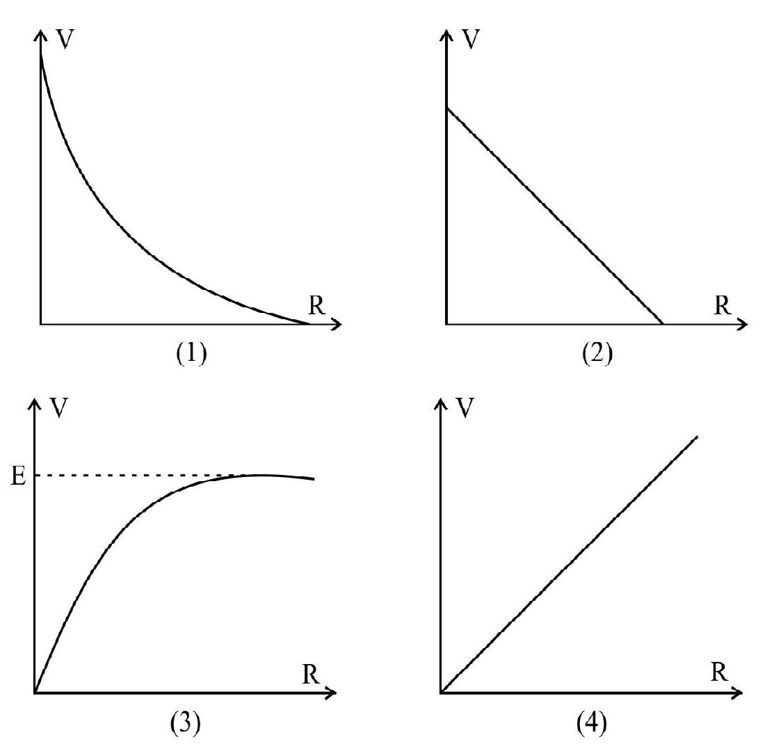
Show Answer
Correct Answer: (3)
Solution:
The circuit is a shown.
The current in this circuit is
Potential V across
It is easy to see that
When
When
Hence option (3) is correct.
Average
Cells in Series
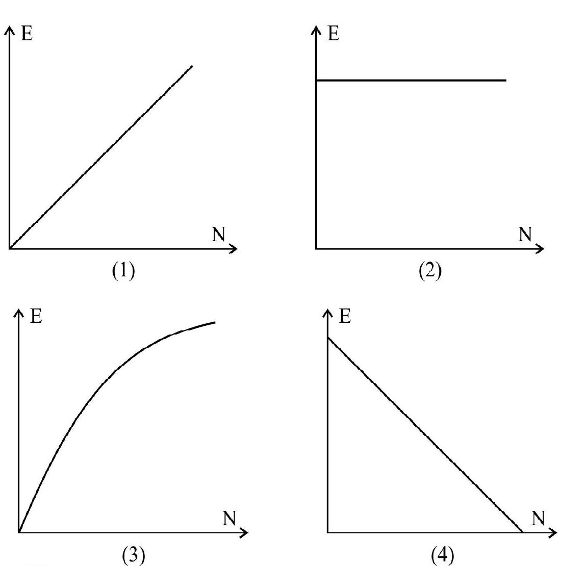
3. N identical cells, each of emf
Then
(1)
(2)
(3)
(4)
Show Answer
Correct Answer: (1)
Solution:

Hence the option (1) is correct.
Average
Cell Combinations
4. A battary of 24 cells each of emf
(1) 6 cells in series and connect 4 such rows in parallel
(2) all the 24 cells in series
(3) all the 24 cells in parallel
(4) 12 cells in series and connect 2 such rows in parallel
Show Answer
Correct Answer: (4)
Solution:
Let us connect cells in mixed grouping where
Then for maximum current in external resistance.
Hence option (4) is correct.
Difficult
Cell Combinations
5. (MN) identical cells, of e.m.f.
(1) Number of cells in a row
(2) Number of cells in a row
(3) Number of cells in a row
(4) Number of cells in a row
Show Answer
Correct Answer: (2)
Solution:
The simplified version of the given circuit is shown in diagram (2) we have,

If the total number of cell is fixed, than
As
or
If
Hence for the maximum current. Number of cell in a row
and number of rows
Average
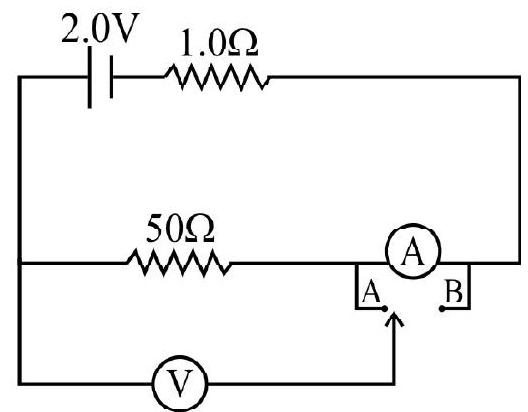
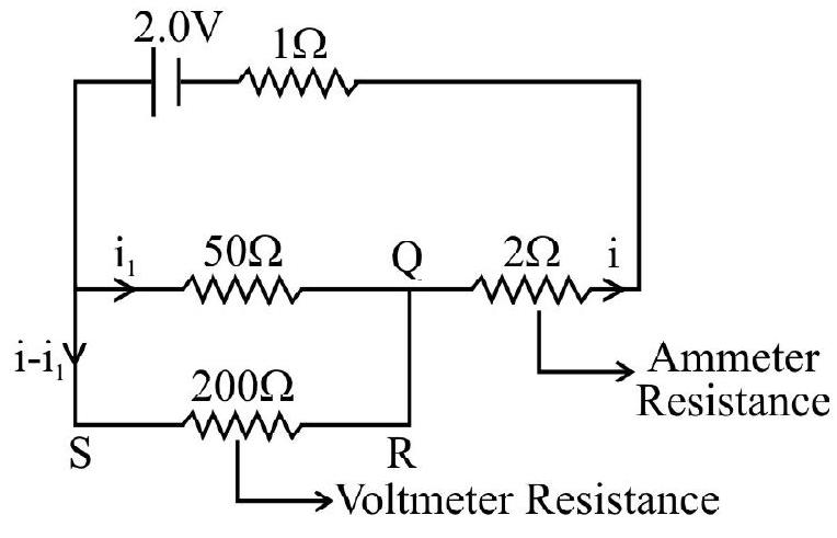
Circuit Analysis
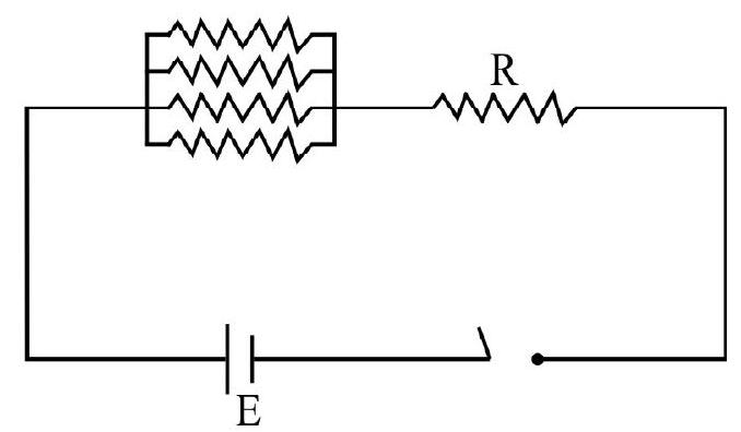
6. You are provided with a test resistance


Show Answer
Correct Answer: (3)
Solution:
Here we have to use galvanometer
Average
Drift Velocity
7: A conductor contains
(1)
(2)
(3)
(4)
Show Answer
Correct Answer: (3)
Solution:
We known that drift velocity
where the symbols have their usual meanings.
Now it is easy to see that
where
Hence,
or
or
Substituting we given values we get,
Hence option (1) is correct.
Easy
Mean Free Path
8: The mean free path of electron in a metal is
(1)
(2)
(3)
(4)
Show Answer
Correct Answer: (3)
Solution:
It is easy to see that the work done is (qE)
Hence,
or
Easy
Resistivity
9. The length of a wire is doubled and current through it is increased by a factor of
(1) remains same
(2) increase by a factor of 3
(3) decrease by a factor of 3
(4) increase by a factor of 2
Show Answer
Correct Answer: (1)
Solution:
The resistivity of a wire depends only on the nature of wire. Changing factors like length, area of cross section does not charge the resistivity of the material of the wire.
Average
Combination of Resistance
10. A wire of uniform resistance
(1)
(2)
(3)
(4)
Show Answer
Correct Answer: (3)
Solution:
Let
If the resistance of straight wires
Hence optino (3) is correct.
Easy
Non Ohmic Devices
11. The relation between
(1) a junction diode
(2) a super conductor
(3) a light emitting diode
(4) a transmiter
Show Answer
Correct Answer: (3)
Solution:
Informative (The material of the light emitting diode is GaAs).
Average
Combination of Resistances
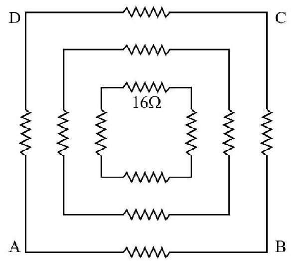
12. Sixteen resistance, each of
(1)
(2)
(3)
(4)
Show Answer
Correct Answer: (4)
Solution:
In each of the four arms of network of resistance four resistance are converted in parallel. The effective resistance of each arm of network is
The total resistance is then given by:
Hence option (4) is correct.
Easy
Resistance of Wire
13. A copper wire is stretched to make it
(1)
(2) No charge
(3)
(4)
Show Answer
Correct Answer: (4)
Solution:
If A is the area of cross sectino of the wire of length
The resistance,
Differentating we get,
Hence option (4) is correct.
Difficult
Resistance Combinations
14.
(1)
(2)
(3)
(4)
Show Answer
Correct Answer: (1)
Solution:
Also,
Similarly,
Hence the option (1) is correct.
Difficult
Resistance Combinations
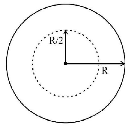
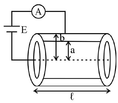
15. A cylinder of radius a, lengths
(1)
(2)
(3)
(4)
Show Answer
Correct Answer: (2)
Solution:
Let
The area of cross section of electroplated part is
Resistance
Hence option (2) is correct.
Difficult
Continuous Variation of Resistance
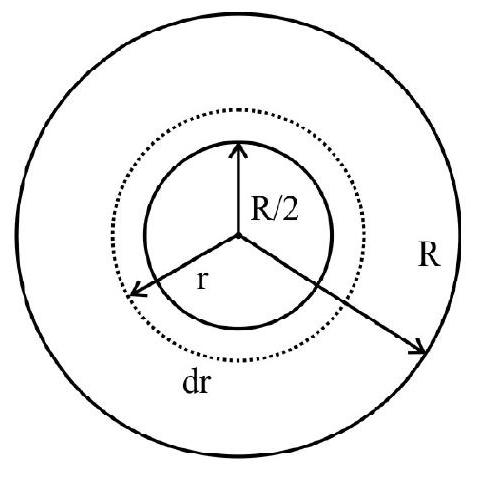
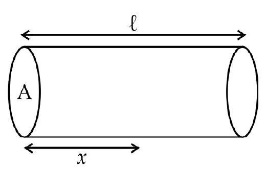
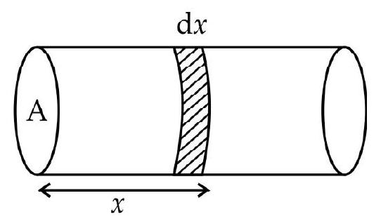
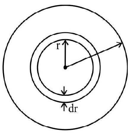
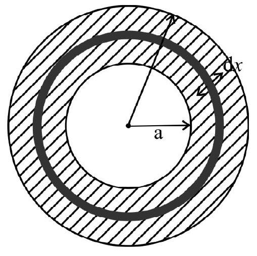
16. A cylinderical wire of radius
(1)
(2)
(3)
(4)
Show Answer
Correct Answer: (2)
Solution:
We consider an element of the cylinderical wire of radius
It can be seen that the current is along the wire and the elementary area
Hence the current through the element of the wire is
Hence the current through the outer portion of the wire is
Hence option (2) is correct.
Average
V-I Graphs
17. The voltage current graph for a platinum wire conductor at temperature
(Given temperature coefficient of platinum is
(1)
(2)
(3)
(4)
Show Answer
Correct Answer: (4)
Solution:
Easy
Dependence of Resistivity on Temperature
18. Which of the following statement is correct?
(1) For metals, resistivity increases linearly with temperature, at all temperatures.
(2) For insulators resistivity decreases expontentially with decreasing temperatures.
(3) For semi conductors resistivity becomes very large at low temperatures tending to infinitely large values as
(4) Resistivity increases with temperatures for metals, insulators as well as semi conductors.
Show Answer
Correct Answer: (3)
Solution:
For semi conductor the resistivity increases exponentially with decreasing temperature, the variation being expressed by the relation of the form
Here
Because of expontatial dependance the resistance of semi conductors becomes very large at low temperature tending to infinite large values as
Hence option (3) is correct.
Average
Dependance of Resistance on Temperature
19. Which of the following statements is incorrect?
(1) The resistance of a thermistor charges very rapidly with charge in temperature.
(2) The temperature co-efficient of resistivity can be both positive and negative.
(3) A thermistor can easily measure a charge in temperature of
(4) The temperature co-efficient of resistivily of a thermistor is normally very low.
Show Answer
Correct Answer: (4)
Solution:
The thermistor is a semi conducting device. The resistivity of a semi conductor increases expontentially with decrease in temperature. The resistivity of a semi conductor increases very large with decrease in temperature tending to inifinity as
Easy
Non-Ohmic Devices
20. Which of the following graphs represent current voltage relationship for a water voltamtere?

Show Answer
Correct Answer: (1)
Solution:
For certain electrolytes like platinum and water, we find that the current flowing through is extremely small until the potential difference increase to a value
Hence option (1) is correct.
Average
Circuit Analysis
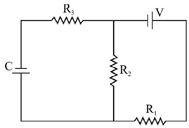
21. Find the steady state voltage drop across the capacitor
(1) V
(2)
(3)
(4)
Show Answer
Correct Answer: (3)
Solution:
Since no d.c. current flows through a capacitor the steady state voltage drop across capacitor is same as across resistance
Here the voltage drop across
Hence option (3) is correct.
Easy
Meter Bridge
22. Figure shows a meter bridge circuit for the determination of an unknown resistance. When we use different values of
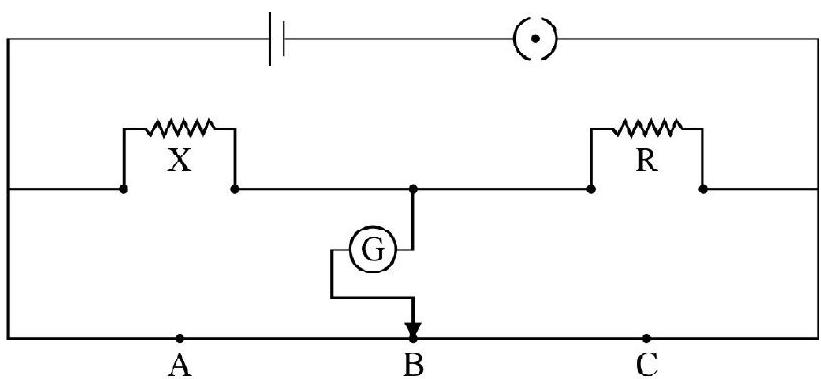
(1)
(2)
(3)
(4) The accuracy of determination will be practically the same whether we use
Show Answer
Correct Answer: (2)
Solution:
Meter bridge is based on the principle of Wheatstone bridge. The balance condition
Average
Meter Bridge
23. Figure shows a meter bridge circuit for measurements of resistance. However the meter bridge wire has end corrections
Taking known
(1)
(2)
(3)
(4)
Show Answer
Correct Answer: (4)
Solution:
We can write
and
Solving these two equations for
Average
Wheatstone Bridge
24. To obtain the optimum sensitivity of a Wheatstone bridge, for a given ‘want of balance’, and with a freedom of choice of arrangment, we should.
(1) Connect the battery so that resistance in series with the resistance to be measured is greater than the resistance in parallel will it.
(2) Connect the battary so that the resistance in series with the resistance to be measured is less than the resistance in parallel will it.
(3) Interchange the position of the battery and the galvanometer.
(4) Use a galvanometer with a reasonable high resistance.
Show Answer
Correct Answer: (1)
Solution:
We can obtain an ideal relation for the sensitivity of a Wheatstone bridge for a given want of balance. However this ideal relation cannot be satisfied in actual working conditions. Hence we look for a rule for optimum senstivity of a wheatstone bridge. The option (1) is a working rule given by Callender for optimum senstivity of a Wheatstone bridge.
Average
Combination of Resistance
25. An infinite ladder network of resistance is constructed with
(1)
(2)
(3)
(4) Infinite
Show Answer
Correct Answer: (2)
Solution:
Let
We this have,
or
Simplifying we have,
or
Since the equivalent resistance cannot be negative we have,
Hence option (2) is correct.
Average
Combination of Resistance
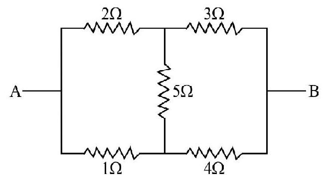
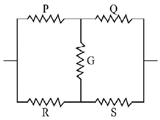
26. Figure shows a network of 5 resistances each of value
(1)
(2)
(3)
(4)
Correct answer: (2)
Show Answer
Solution:
The given network forms a balanced wheatstone bridge. Hence the resistance between
Hence option (2) is correct.
Average
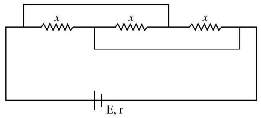
Combination of Resistances
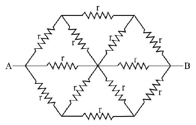
27. Six equal resistance each of value
(1)
(2)
(3)
(4)
Correct answer: (3)
Show Answer
Solution:
The upper five resistance between
The effective resistance
or
Hence option (3) is correct.
Difficult
Combination of Resistances
28. Figure shows the connections of six resistances each of value
(1) A and B
(2) B and C
(3) A and C
(4) The net value of the resistance between
Show Answer
Correct Answer: (1)
Solution:
In the branch
The resistance of branch ACB is in parallel to resistance of branch AB. This effective resistance between
Similarly the resistance between B and C is
Hence option (1) is correct.
Difficult
Circuit Analysis
29. A battery, of internal resistance
To deliver the maximum power to the network the value of,
(1) 2
(2)
(3)
(4)
Show Answer
Correct Answer: (1)
Solution:
The given network can be reduced to a balanced Wheatstone bridge as shown. Hence no current flows through side
The given circuit forther reduces to.
To obtain maximum power, the net external resistance must be equal to total internal resistance.
or
Hence option (1) is correct.
Average
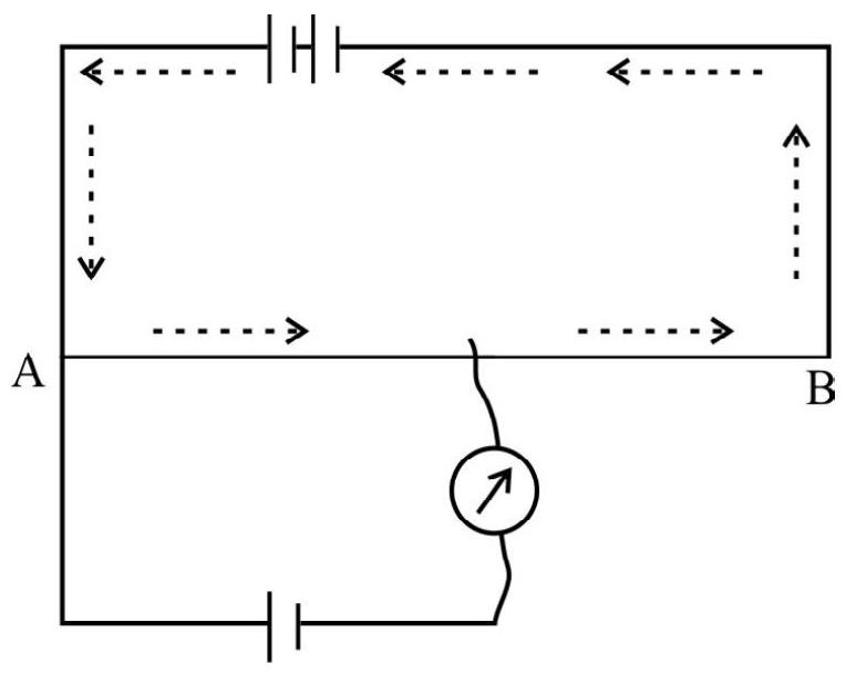
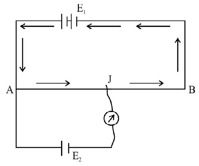
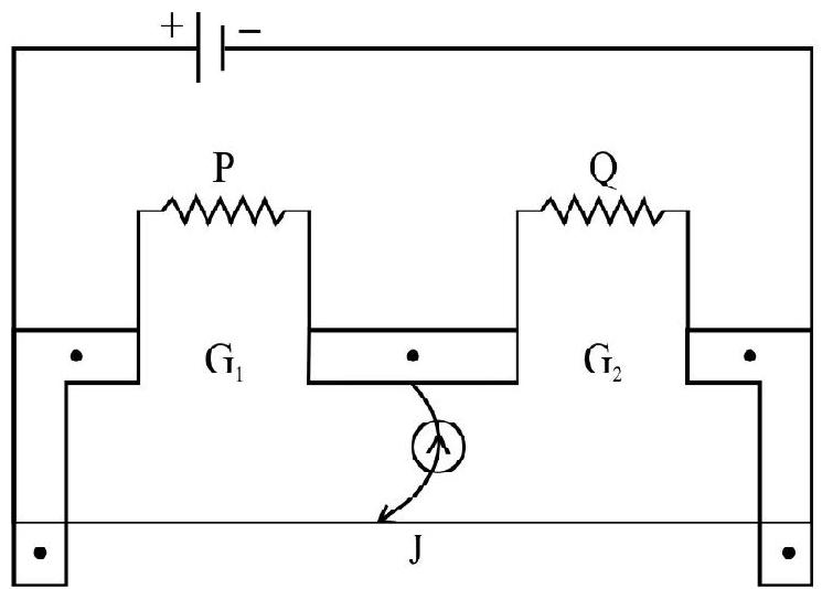
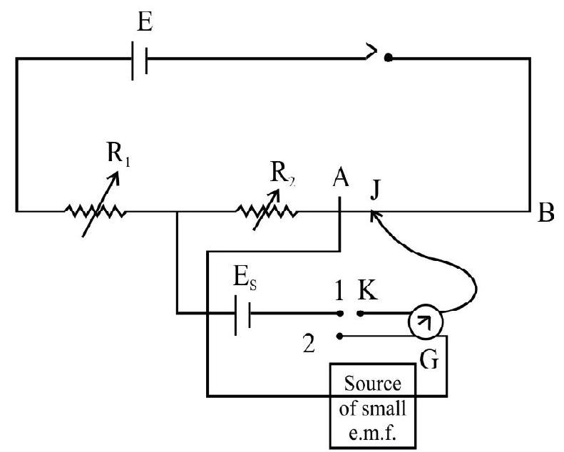
Potentiometer
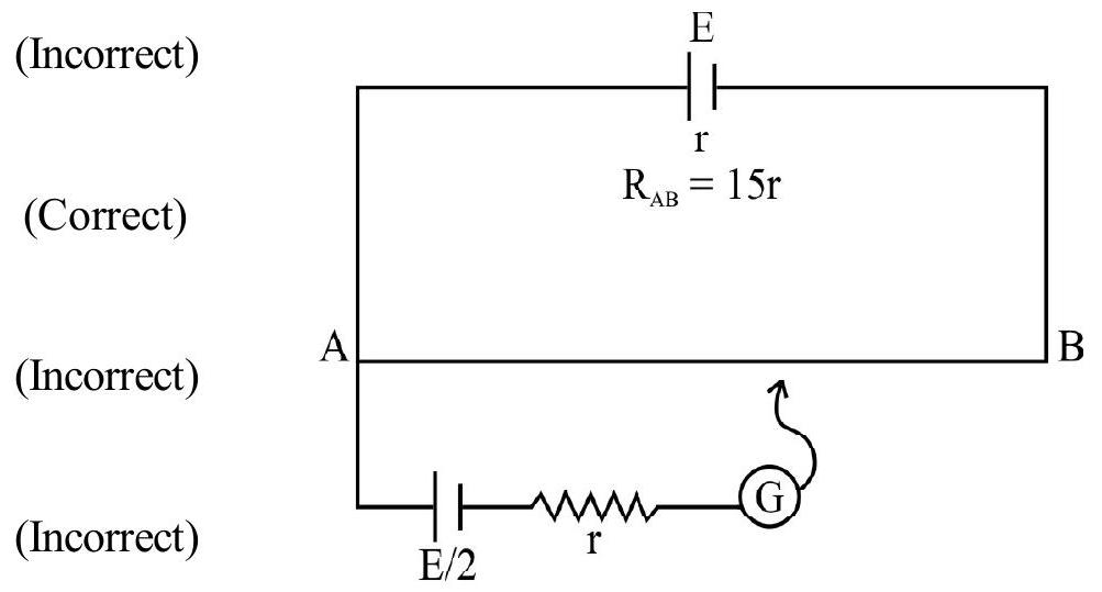
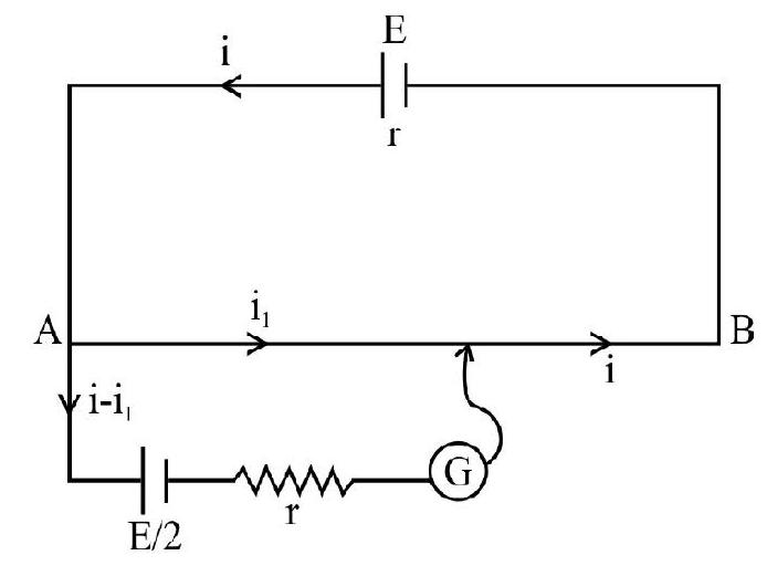
30. A potentiometer circuit is shown in figure.
(1) The main battery is connected in an incorrect manner.
(2) The e.m.f. of the main battery is less than unknown e.m.f.
(3) The unknown e.m.f. is less than that of the main battery.
(4) That is a broken connection in the galvanomter circuit.
Show Answer
Correct Answer: (1)
Solution:
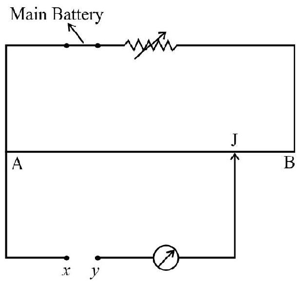
In a potentiometer we balance an unknown e.m.f. against potential drop a portion of length of the potentiometer wire. We find that the deflaction is in the same direction and increases as we move from one end A to another and B of the potentiometer wire it is clear that external e.m.f. is superimposing on drop of potential across AJ. This indicates the external e.m.f. between points
Hence option (1) is correct.
Average
Potentiometer
31. A potentiometer circuit is shown in figure
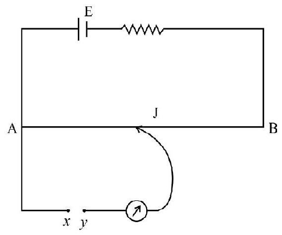
(1) The unknown e.m.f.
(2) The unknown e.m.f.
(3) The unknown e.m.f. is much less than E.
(4) The total drop of potential e.m.f. across the pontentiometer wire is less than the unknown.
Show Answer
Correct Answer: (4)
Solution:
When we find that deflation decreases when we move form end A to the other end B, the unknown emf
Average
Potentiometer
32. Figuqre shows a potentiometer with a cell of
similarly turn out to be
(1) To aclieve this measurement we should replace the high resistance of
(2) Increase the potential gradient of the potentiometer wire by a factor of at least 100.
(3) Decrease the potential gradient of the potentiometer wire by at least a factor of 100 by connecting suitable low resistance in series with the potentiometer wire.
(4) Decrease in potential gradient of potentiometer wire by a factor of more than 100 by connecting a suitable high resistance in series with the potentiometer wire.
Show Answer
Correct Answer: (4)
Solution:
The potential gradient of given wire is
Usually R is of the order of a few ohm while
Hence
It follows that the balance length for a small e.m.f. would be only a few
Hence option (4) is correct.
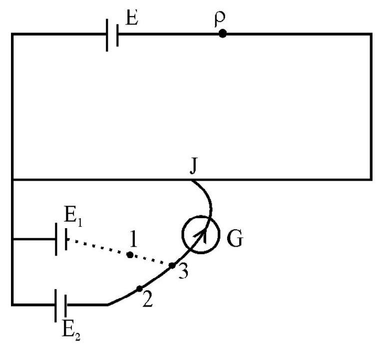
Potentiometer
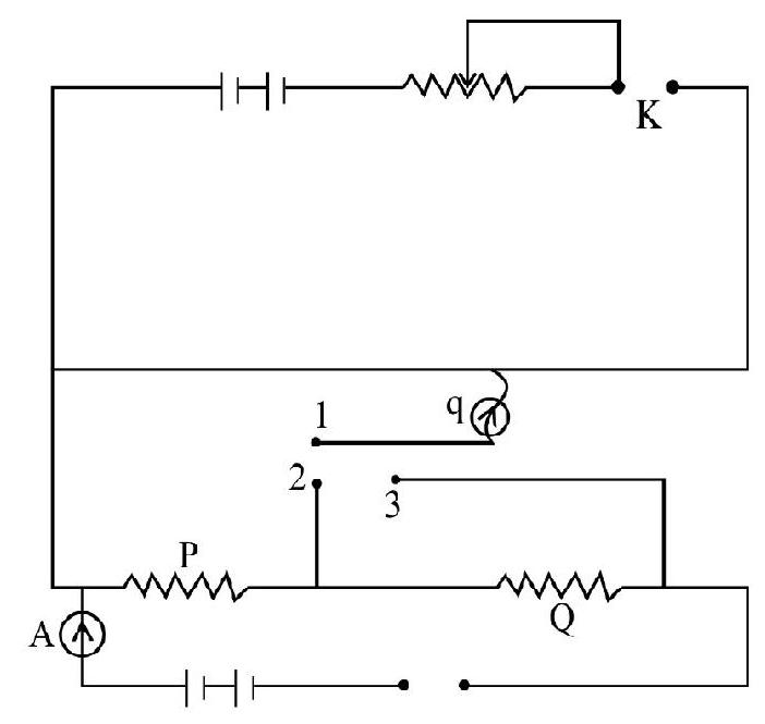
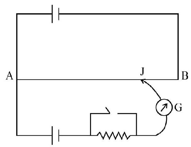
33. Which of the following statements is correct?
(1) A potentiometer can only be used for comparing two e.m.f.’s
(2) A potentiometer cannot be used to measure a high e.m.f.
(3) A potentiometer cannot be used for measuring thermo e.m.f.
(4) A potentiometer can be used for measuring high emf’s as well as very small e.m.f.’s
Show Answer
Correct Answer: (4)
Solution:
A potentiometer can be used for measuring a high e.m.f. The circuit diagram is shown in figures. Here the large e.m.f. to be measured is connected with two resistances
We first connect 1 and 3 and 2’ and 3’. The potential drop produced across
Potential drop across
or
Drop across potentiometer wire is
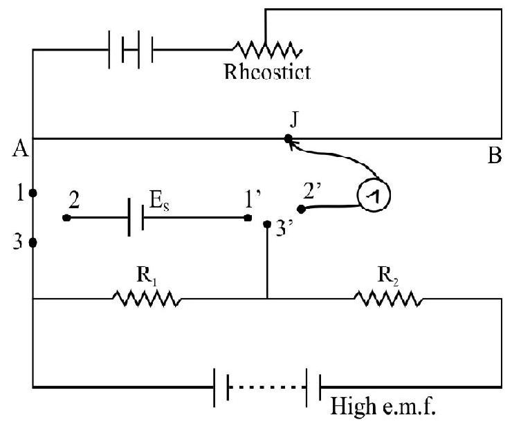
The potential gradient therefore is
The small e.m.f. to be measured is now brought into circuit by making contact between 2 and K. If L’ is the balance length, the
The circuit shown is used for the measurement of low resistance. Here we set the total potential drop across the potentioneles small.
The small potential drop cross the potentiometer is measured accurately using a standard cell let
Total potential drop across potentiometer wire
We adjust the value of
The potential gradient therefore is
The small emf to be measured is now brought into circuit by making connection between 2 and
e
Hence option (4) is correct.
Average
Heating Effect of Current
34. An electric tea kettle has two heating coils. When one of coils is switched on, the kettle begins to boil in 6 minutes. When the other is switched on the kettle begin to boil in 8 minutes. It boil the coils are switched on simultaneously and connected in parallel then the kettle will begin to boil in.
(1) 14 minutes
(2) 205.7 seconds
(3)
(4) 48 minutes
Show Answer
Solution:
Let
Now,
Thus,
or
Hence option (2) is correct.
Easy
Heating Effect of Current
35. Lamps A and
(1) Both bulbs have same intensily
(2) Intensity of bulb
(3) Intensity of bulb
(4) Initially both have same intensity but, after a sufficiently long time, intensity of bulb
Show Answer
Correct Answer: (1)
Solution:
Since both carbon and tengsten have same resistance (say
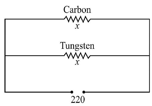
Hence both bulbs have the same intensity.
Hence option (1) is correct.
Average
Power Consumption in a Circuit
36. Six Diwali tree lights are arranged in a parallel circuit as shown in figure. Each bulb dissipates
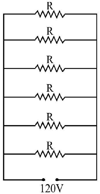
(1) 600 Watt
(2) 0.6 Watt
(3) 120 Watt
(4) 60 Watt
Show Answer
Correct Answer: (4)
Solution:
Resistance of the each buls
The given 6 resistance are connected in parallel, therefore equivalent resistance is given by:
Hence the power consumed by the given arrangment is given by
Hence option (4) is correct.
Average
Heating Effect of Currents
37. A copper wire, having cross sectional area of
(1)
(2)
(3)
(4)
Melting point of copper
Spefic resistance of copper
Density of copper
Specific heat capacity of copper
Show Answer
Correct Answer: (2)
Solution:
We can easily see that
or
In above relation
Substituting the values we get
Hence option (2) is correct.
Average
Heating Effect of Currents
38. Two wires, made of tinned copper, having identical cross section and different lengths, are used as fuses. Then
(1) Two wires fuses will melt at different values of the current.
(2) Two wire fuses will melt at the same value of current
(3) Two wire fuses will only melt at the same value of the current only if they we of equal lenghts
(4) Two wires fuses will only melt at the same value of current if they have same resistivity
Show Answer
Correct Answer: (2)
Solution:
If a current I flows into a fuse wire, the rate of loss of heat from the fuse wire is given by the relation.
or
or
Since the area of cross section of bulb wires is identical, so the radius of both the wires will be same. Since
Average
Heating Effect of Currents
39. A fuse, with a radius of
(1)
(2)
(3)
(4)
Show Answer
Correct Answer: (3)
Solution:
The relation between the heat produced and current in a fuse wire of radius
Hence we have,
Solving for
Hence option (3) is correct.
Average
Heating Effect of Currents
40. Three equal resistance each of value
(1)
(2)
(3)
(4)
Show Answer
Correct Answer: (2)
Solution:
If
Now,
Also,
Hence,
For maximum heat to be produced
or
But,
Hence option (2) is correct.
Average
Resistance Variation with Length, Area & Nature of Material
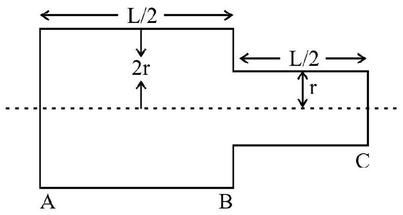
41. Following figure showns cross section through three long conductor of same length and material, with circular cross sections as shown in figure. Conductor B will fit exactly within conductor

(1)
(2)
(3)
(4) Given data not sufficient
Show Answer
Correct Answer: (1)
Solution:
As the length of all conductors is equal and ’
Now, area of cross section of conductor
and of conductor
Area of cross section of conductor
As resistance of a conductor is given by
Hence answer (1) is correct.
Difficult
Grouping of Resistances
42. The equivalent resistance of the network between points
(1)
(2)
(3)
(4)
Show Answer
Correct Answer: (1)
Solution:
Current distribution at point
Therefore, circuit can be redrawn like as shown
Applying
But,
Hence effective resistance between ponits A& B
Alternative (Short cut)
Here,
Hence effective resistance between point A&B
Hence option(1) is correct
Difficult
Ohm’s Law and Current Density
43. The given figure shows a conductor of length ’
(1)
(2)
(3)
(4)
Show Answer
Correct Answer: (2)
Solution:
Current flowing
Current density
Electric field
Hence option (2) is correct.
Average
Discharging of Cell
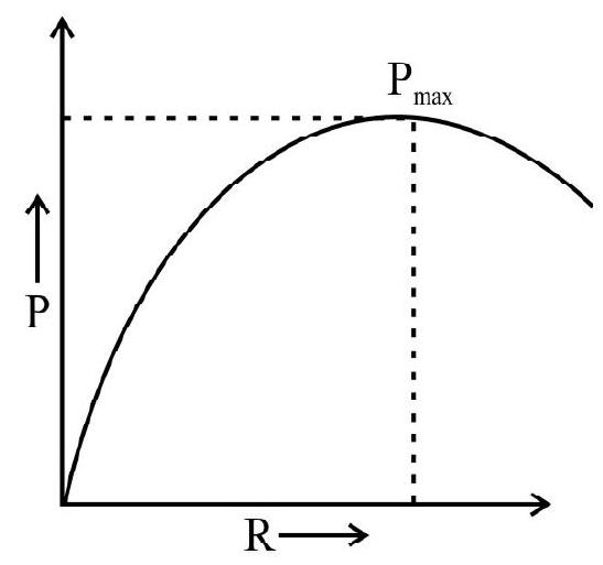
44. Given graph shows the variation of power dissipated in external resistnace (Load)
(1)
(2)
(3)
(4)
Correct answer: (1)
Show Answer
Solution:
Current given by the cell of the resistance
Power dissipated in external resistance (load)
Power will be maximum when
For
Hence option(1) is correct
Difficult
Potentiometer
45. In the given figure
(1)
(2)
(3)
(4)
Show Answer
Correct Answer: (2)
Solution:
Resistance of potentiometer wire
Resistance of the length
Applying KVL in loop APMA
Applying KVL to loop AEBA
Solving (1) & (2)
Putting the value of
ir
Hence current through galvanometer
Hence option (2) is correct.
Difficult
Meter Bridge
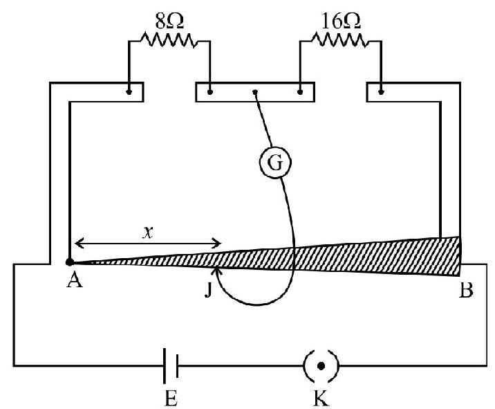
46. In the given experimental setup of meter bridge the length of the wire is one meter but its radius is increasing linearly from end
(1)
(2)
(3)
(4)
Show Answer
Correct Answer: (2)
Solution:
Let ’
‘dR’ = Resistance of this element
Similarly resistance of the remaining wire i.e. from
As the bridge is balanced at distance
Hence option (2) is correct.
Difficult
Grouping of Resistors
47. In the given circuit, each resistance is of
(1)
(2)
(3)
(4)
Correct answer: (1)
Show Answer
Solution:
As the paths
The potential difference
Hence on elimination of
Hence option (1) is correct.
Difficult
Combination of Resistances
48. The equivalent resistance between points
(1)
(2)
(3)
(4)
Correct answer: (3)
Show Answer
Solution:
Current distribution in the given figure will be as follows, (due to symmetry at points a and c).
Hence option (3) is correct.
Difficult
Power Delivered to a Resistor (Max. Power Transfer Theorem)
49. In the given figure,
(1) 500 second
(2) 400 second
(3) 100 second
(4) 150 second
Correct answer: (3)
Show Answer
Solution:
In loop 1:
In loop 2:
Putting the value of
Hence power dissipated
For power to be maximum
Since rate of increase of resistance is
i.e.
Hence optino (3) is correct.
Difficult
Heating Effect
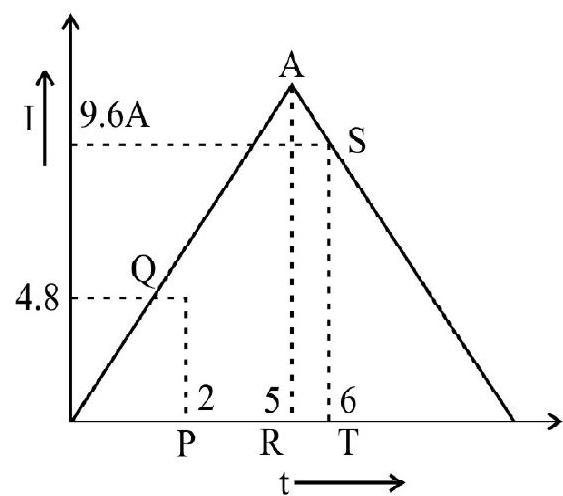
50. In the given figure, the charge supplied by the source varies as a function of time as
(1)
(2)
(3)
(4)
Show Answer
Correct Answer: (1)
Solution:
Current
Hence current in
Charge flowing from the source will be zero at
Hence total heat produced in
Hence option (1) is correct.
Difficult
Current Density
51. The current density in a cylindrical wire of radius
(1)
(2)
(3)
(4)
Show Answer
Correct Answer: (1)
Solution:
Area dA
Hence,
Hence option (1) is correct.
Average
Current
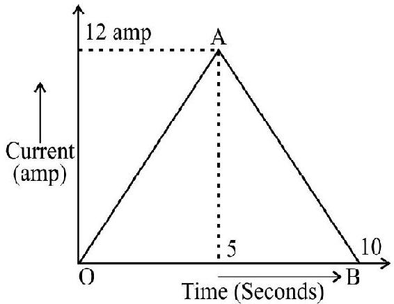
52. The given graph shows the variation of current with time in a circuit for
(1) 60 Coulomb
(2) 30 Coulomb
(3) 24 Coulomb
(4) 36 Coulomb
Show Answer
Correct Answer: (4)
Solution:
The rate of growth of current upto 5 seconds.
The rate of decay of current from
Hence chrage between 2 second and 6 second
Hence option (4) is correct.
Difficult
Unbalanced Wheatstone Bridge
53. The equivalent resistance between points
(1)
(2)
(3)
(4)
Show Answer
Correct Answer: (3)
Solution:
Hence option (3) is correct.
Alternative : can be determined using Kirchoff’s laws.
Average
Current Distribution
54. In the network points
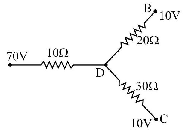
(1) Potential at point
(2) The currents in the section
(3) The network draws a totoal power of
(4) All the above
Show Answer
Correct Answer: (1)
Solution:
From (1) & (2)
Hence
Hence option (1) is correct
Aeverage
Combination of Resistances
55. The equivalent resistance between point
(1)
(2)
(3)
(4)
Show Answer
Correct Answer: (3)
Solution:
Due tosymmetry of the figure. It can be reduced.

Hence option (3) is correct
Average
Calculation of Resistance
56. A material of resistivity ’
(1)
(2)
(3)
(4)
Show Answer
Correct Answer: (4)
Solution:
Let the resistance of the small element
Hence option (4) is correct.
Average
Potentiometer
57. In an arrangement, for the determination of internal resistance of a battery using potentiometer, the null point is obatined at
(1)
(2)
(3)
(4)
Show Answer
Correct Answer: (1)
Solution:
When a resistance of
Hence internal resistance
Hence option (1) is correct.
Average
Heating Effect of Current
58. A nichrome Filament heater consumes
(1)
(2)
(3)
(4)
Show Answer
Solution:
As,
Hence correct option is (2).
Average
Grouping of Cells
59. Two cells
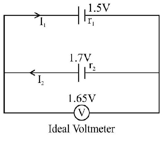
(1)
(2)
(3)
(4)
Show Answer
Correct Answer: (1)
Solution:
Also,
Ideal Voltmeter
Dividing
Hence option (1) is correct.
Average
Potentiometer
60. The given figure shows a potentiometer wire of length
(1)
(2)
(3)
(4)
Show Answer
Correct Answer: (1)
Solution:
From figure, when the value of resistance
then current in the potentiometer wire
Hence potential drop across the wire
Since cell of emf ’
Now current becomes
Now potential gradient
2.0 or
Hence option (1) is correct.
Average
Current Distribution
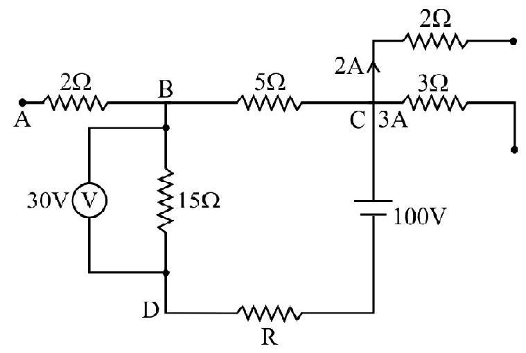
61. In the given figure, ideal voltmeter reads
Then potential difference across
(1)
(2)
(3)
(4)
Show Answer
Correct Answer: (1)
Solution:
The current flowing in branch BD is
Hence potential difference between points
Applying KVL to loop BDCB
Hence option (1) is correct.
Average
Combination of Resistances
62. In the given figure, each resistance is of
(1)
(2)
(3)
(4)
Show Answer
Correct Answer: (2)
Solution:
Let current I enters at point A, and divide into three branches equally i.e.
Hence
Option (2) is correct.
Average
Resistance of conductors
63. Two conductos, one solid and other hollow are made up of same material, the length of solid conductor is twice the length of hollow conductor and diameter is
(1)
(2)
(3)
(4)
Show Answer
Correct Answer: (3)
Solution:
Hence option (3) is correct.
Average
Potentiometer
64. In the following circuit, the potential difference between the points
(1)
(2)
(3)
(4)
Show Answer
Correct Answer: (4)
Solution:
Current in loop AKBCDA
Hence potential difference between points
and between points
According to given figure
Now,
Hence option (4) is correct.
Average
Current Distribution
65. In the given circuit, the battery of emf
(1)
(2)
(3)
(4)
Show Answer
Correct Answer: (4)
Solution:
Net resistance of the combination.
Hence current idrawn from the cell.
In loop PQRS
Hence current through voltmeter
Hence voltmeter reading
Ammeter readind
Easy
Calculation of Current
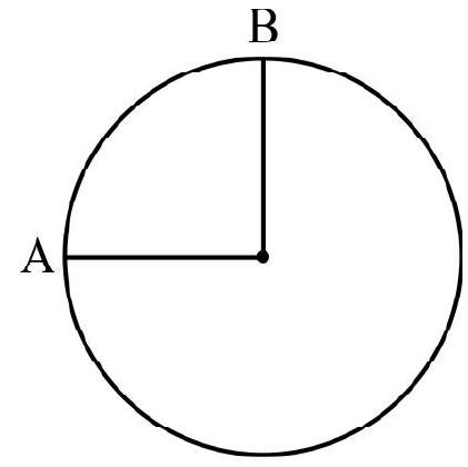
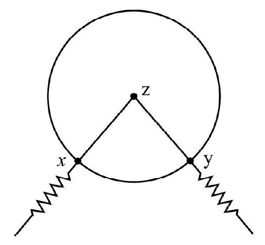
66. The electron in an hydrogen atom moves in a circular orbit of radius
(1) The frequency of the electron is
(2) The electron carries
(3) The current in the orbit is
(4) The current flows in the same direction in which electrons move
Show Answer
Correct Answer: (3)
Solution:
Also,
Hence option (3) is correct.
Average
Potential Differnece
67. In the circuit shown, the cell is ideal, with emf
(1)
(2)
(3)
(4) zero
Show Answer
Correct Answer: (3)
Solution:
No current will flow through the branch containing capacitor.
Hence current drawn from the cell
Hence p.d. between points B & D
Hence option (3) is correct.
Easy (Knowledge Based)
Current Density
68. Two bars of radius
(1) Heat produced in bar
(2) Electric field in both bars have the same value
(3) Current density across
(4) Potential difference across
Show Answer
Solution:
As the resistance of Bar
(Area)
Heat produced
For same current heat produced will be four times.
Hence option (1) is correct.
Average
Effect on Resistance on Stretching
69. A wire of resistance
(1)
(2)
(3)
(4)
Show Answer
Correct Answer: (1)
Solution:
Resistance of each part on cutting
After stretching resistance of each part will be 16 times
Effective resistance in series
Effective resistance in parallel
Hence option (1) is correct.
Average
Combination of Resistance and Division of Current in Parallel Combination
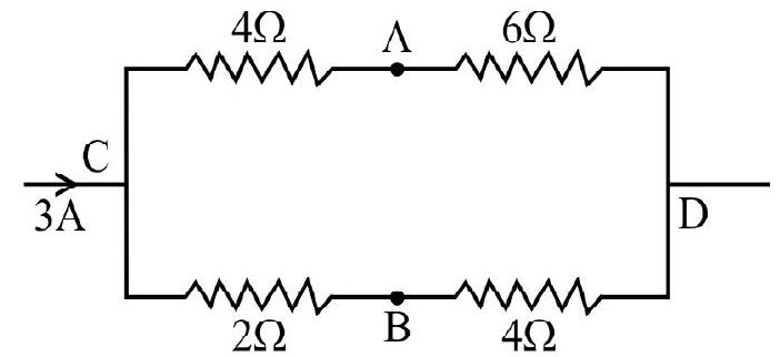
70. The current of 3A flows in the combination of resistance as shown in figure, the potential difference between points
(1)
(2) zero
(3)
(4)
Show Answer
Correct Answer: (4)
Solution:
The given circuit can be reduced to the circuit as shown here
Current in
Current in
From given figure
Hence,
Hence option(4) is correct
Average
Cell and Distribution of Current
71. In the given figure, the emf of the battery will be
(1)
(2)
(3)
(4)
Show Answer
Correct Answer: (2)
Solution:
Current entering at point
Hence current through
and current in branch
Total resistance in the circuit
Hence
Hence option (2) is correct.
Average
Distribution of Current
72. In the given circuit diagram, the current flowing through branch ab and bd will be:
(1)
(2)
(3)
(4)
Show Answer
Correct Answer: (4)
Solution:
The resistance between the points
Current in branch
Hence correct option is (4).
Average
Distribution of Current
73. In the given circuit, current through branch de and the ammeter reading will be
(1)
(2) 0 A and
(3) 0 A and
(4)
Show Answer
Correct Answer: (3)
Solution:
The effective resistance between points
Hence current drawn from battery
Therefore current through branch
Easy
Combination of Resistances
74. Two resistances
(1)
(2)
(3)
(4)
Show Answer
Correct Answer: (4)
Solution:
In series
In parallel
Given,
Hence alternative (4) is correct.
Average
Resistance
75. A hollow cylinder of length ’
(1)
(2)
(3) infinite
(4) zero
Show Answer
Correct Answer: (1)
Solution:
Resistance of an imaginary cylinder of radius
So the resistance of given cylinder
Hence reading of ammeter
Hence option (1) is correct.
Easy
Temperature Dependence of Resistance
76. A piece of silver and another of germanium cooled from room temperature to
(1) Each of then increases
(2) Each of then decreases
(3) That of silver increases and germanium decreases
(4) That of silver decreases and that of germanium decreases
Show Answer
Correct Answer: (4)
Solution:
Silver is a metal and germanium is a semi conductor. Resistance of metal decrease and that of a semi conductor increases with decreases in temperature.
Hence option (4) is correct
Average
Using Ohm’s Law
77. In a discharge tube the number of hydrogen ions drifting across a cross section per second is
(1)
(2)
(3)
(4)
Show Answer
Correct Answer: (2)
Solution:
The effective current in the tube will be obtained by adding the current due to flow of protons in one direction and the flow of electrons in opposite direction. Hence the total current through the tube is
Average
Driff Velocity
78. A silver wire has a radius of
We are given:
Auogaidro’s number
Atomic weight of silver
Density of silver
Charge on the electron
(1)
(2)
(3)
(4) 0.7
Show Answer
Correct Answer: (1)
Solution:
Since the valence of silver is one so each atom of silver can be assumed to contribute one electron.
By Avogadro’s law, we have
Hence number of electrons per unit volume will be
Cross sectional area
Now we know I = nevA where
or
Hence option (1) is correct.
Average
Factors Affecting Resistance
79. A one meter long metallic wire is broken into two unequal parts
(1)
(2)
(3)
(4)
Show Answer
Correct Answer: (2)
Solution:
Let
The length of wire
Length of wire
Mass of
Than,
and
Hence,
Hence option (2) is correct.
Average
Heating Effects of Currents
80. A wire, of resistance
(1)
(2)
(3)
(4)

Show Answer
Correct Answer: (3)
Solution:
In the first case have,
or
In the second case the
or
If
or
or
or
Hence option (3) is correct.
81. The supply voltage to a room is
(1) 2.9 Volt
(2) 13.3 Volt
(3) 10.04 Volt
(4) zero Volt
Show Answer
Correct Answer: (3)
Solution:
’
‘R’ for Heater
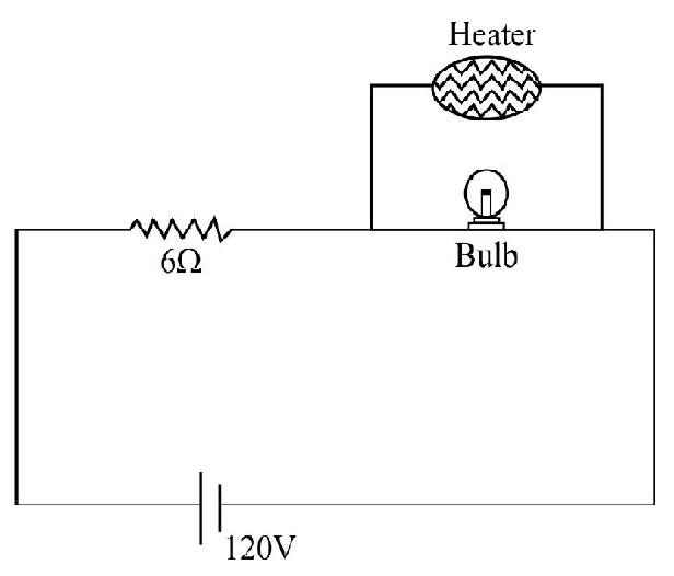
Voltage, across the bulb,
(i) Before heater is switched on
(ii) After heat is switched on
Hence option (3) is correct.
82. In a large building, there are 15 bulbs of
(1)
(2)
(3)
(4)
Show Answer
Correct Answer: (1)
Solution:
Total power of all the devices
Hence option (1) is correct.
83. When
(1)
(2)
(3)
(4)
Correct answer: (2)
(IIT 2015)
Show Answer
Solution:
Hence option (2) is correct.
84. In the circuit shown, the current in the
(1)
(2)
(3)
(4)
Correct answer: (1)
Show Answer
Solution:
By using Kirchoff’s laws, we find the current in the
85. The temperature dependence of resisatnces of
(1) Linear increase for
(2) Linear increase for
(3) Linear decrease for
(4) Linear increase for
Show Answer
Correct Answer: (2)
Solution:
For conductors
Resistance increases linearly (for not to large increase in temperature) with temperature.
For semi-conductors
Resistance decreases non-linearly is an (almost) exponential way.
Hence option (2) is correct.


