Alternating Current
Multiple Choice Questions (MCQs)
1. If the rms current in a $50 \mathrm{~Hz} \mathrm{AC}$ circuit is $5 \mathrm{~A}$, the value of the current $1 / 300 \mathrm{~s}$ after its value becomes zero is
(a) $5 \sqrt{2} \mathrm{~A}$
(b) $5 \sqrt{3 / 2} \mathrm{~A}$
(c) $5 / 6 \mathrm{~A}$
(d) $5 / \sqrt{2} \mathrm{~A}$
Show Answer
Answer
(b) Given,
$$ \begin{aligned} & v=50 \mathrm{~Hz}, I_{\mathrm{rms}}=5 \mathrm{~A} \\ & t=\frac{1}{300} \mathrm{~s} \end{aligned} $$
We have to find $I(t)$
$$ \begin{aligned} I_{0} & =\text { Peak value }=\sqrt{2}, I_{\mathrm{rms}}=\sqrt{2} \times 5 \\ & =5 \sqrt{2} \mathrm{~A} \\ I & =I_{0} \sin \omega t=5 \sqrt{2} \sin 2 \pi v t=5 \sqrt{2} \sin 2 \pi \times 50 \times \frac{1}{300} \\ & =5 \sqrt{2} \sin \frac{\pi}{3}=5 \sqrt{2} \times \frac{\sqrt{3}}{2}=5 \sqrt{3 / 2} \mathrm{~A} \end{aligned} $$
-
Option (a): $5 \sqrt{2} \mathrm{~A}$
- This option is incorrect because it represents the peak value of the current, not the instantaneous value at $t = \frac{1}{300} \mathrm{~s}$. The peak value is $I_0 = 5 \sqrt{2} \mathrm{~A}$, but the instantaneous value at the given time is different.
-
Option (c): $5 / 6 \mathrm{~A}$
- This option is incorrect because it does not correspond to the correct calculation of the instantaneous current at $t = \frac{1}{300} \mathrm{~s}$. The correct calculation involves using the sine function and the angular frequency, which results in a different value.
-
Option (d): $5 / \sqrt{2} \mathrm{~A}$
- This option is incorrect because it represents the RMS value of the current, not the instantaneous value at $t = \frac{1}{300} \mathrm{~s}$. The RMS value is $I_{\mathrm{rms}} = 5 \mathrm{~A}$, and dividing by $\sqrt{2}$ does not yield the correct instantaneous value at the specified time.
2. An alternating current generator has an internal resistance $R_{g}$ and an internal reactance $X_{g}$. It is used to supply power to a passive load consisting of a resistance $R_{g}$ and a reactance $X_{L}$. For maximum power to be delivered from the generator to the load, the value of $X_{L}$ is equal to (a) zero (b) $X_{g}$ (c) $-X_{g}$ (d) $R_{g}$
Show Answer
Answer
(c) For delivering maximum power from the generator to the load, total internal reactance must be equal to conjugate of total external reactance.
Hence,
$$ \begin{aligned} X_{\text {int }} & ={ }^* X_{\text {ext }} \\ X_g & =\left(X_L\right)^*=-X_{L} \\ X_L & =-X_g \end{aligned} $$
-
Option (a) zero: If ( X_L ) is zero, the load would be purely resistive. This does not satisfy the condition for maximum power transfer in AC circuits, which requires the reactance of the load to be the negative of the generator’s reactance.
-
Option (b) ( X_g ): If ( X_L ) is equal to ( X_g ), the reactances would add up, resulting in a higher total reactance. This would not maximize power transfer, as the condition for maximum power transfer requires the reactance of the load to be the negative of the generator’s reactance.
-
Option (d) ( R_g ): ( X_L ) being equal to ( R_g ) is incorrect because ( R_g ) is a resistance, not a reactance. The condition for maximum power transfer in AC circuits involves matching the reactance, not the resistance.
3. When a voltage measuring device is connected to $A C$ mains, the meter shows the steady input voltage of $220 \mathrm{~V}$. This means
(a) input voltage cannot be $\mathrm{AC}$ voltage, but a $\mathrm{DC}$ voltage
(b) maximum input voltage is $220 \mathrm{~V}$
(c) the meter reads not $v$ but $\left\langle v^{2}\right\rangle$ and is calibrated to read $\sqrt{\left\langle v^{2}\right\rangle}$
(d) the pointer of the meter is stuck by some mechanical defect
Show Answer
Answer
(c) The voltmeter connected to $\mathrm{AC}$ mains reads mean value $\left(\left\langle v^{2}\right\rangle\right)$ and is calibrated in such a way that it gives value of $\left\langle v^{2}\right\rangle$, which is multiplied by form factor to give rms value.
-
(a) Input voltage cannot be AC voltage, but a DC voltage: This is incorrect because the meter is designed to measure AC voltage and can display the RMS value of an AC voltage. The steady reading of 220V does not imply that the voltage is DC.
-
(b) Maximum input voltage is 220V: This is incorrect because the meter shows the RMS (root mean square) value of the AC voltage, not the peak or maximum value. The maximum (peak) voltage for an AC signal with an RMS value of 220V would be higher, specifically (220V \times \sqrt{2} \approx 311V).
-
(d) The pointer of the meter is stuck by some mechanical defect: This is incorrect because a stuck pointer would not provide a reliable or steady reading. The steady reading of 220V indicates that the meter is functioning correctly and measuring the RMS value of the AC voltage.
4. To reduce the resonant frequency in an $L-C-R$ series circuit with a generator
(a) the generator frequency should be reduced
(b) another capacitor should be added in parallel to the first
(c) the iron core of the inductor should be removed
(d) dielectric in the capacitor should be removed
Show Answer
Answer
(b) We know that resonant frequency in an $L-C-R$ circuit is given by
$$ v_{0}=\frac{1}{2 \pi \sqrt{L C}} $$
Now to reduce $v_{0}$ either we can increase $L$ or we can increase $C$.
To increase capacitance, we must connect another capacitor parallel to the first.
-
(a) Reducing the generator frequency does not affect the resonant frequency of the circuit, which is determined by the values of the inductor (L) and capacitor (C), not the generator frequency.
-
(c) Removing the iron core of the inductor would decrease the inductance (L), which would actually increase the resonant frequency, not reduce it.
-
(d) Removing the dielectric in the capacitor would decrease the capacitance (C), which would also increase the resonant frequency, not reduce it.
5. Which of the following combinations should be selected for better tuning of an $L-C-R$ circuit used for communication?
(a) $R=20 \Omega, L=1.5 \mathrm{H}, C=35 \mu \mathrm{F}$
(b) $R=25 \Omega, L=2.5 \mathrm{H}, \mathrm{C}=45 \mu \mathrm{F}$
(c) $R=15 \Omega, L=3.5 \mathrm{H}, C=30 \mu \mathrm{F}$
(d) $R=25 \Omega, L=1.5 \mathrm{H}, \mathrm{C}=45 \mu \mathrm{F}$
Show Answer
Thinking Process
For better tuning of an L-C-R circuit used for communication, quality factor of the circuit must be as high as possible.
Answer
(c) Quality factor $(Q)$ of an $L-C-R$ circuit is given by,
$$ Q=\frac{1}{R} \sqrt{\frac{L}{C}} $$
where $R$ is resistance, $L$ is inductance and $C$ is capacitance of the circuit. To make $Q$ high,
$R$ should be low, $L$ should be high and $C$ should be low.
These conditions are best satisfied by the values given in option (c).
Note We should be careful while writing formula for quality factor, because we are considering series L-C-R circuit.
-
Option (a): The resistance ( R = 20 \Omega ) is higher than the resistance in option (c), which makes the quality factor ( Q ) lower. Additionally, the inductance ( L = 1.5 \mathrm{H} ) is lower than in option (c), which also contributes to a lower ( Q ).
-
Option (b): The resistance ( R = 25 \Omega ) is higher than the resistance in option (c), which makes the quality factor ( Q ) lower. Although the inductance ( L = 2.5 \mathrm{H} ) is higher than in option (a), it is still lower than in option (c). The capacitance ( C = 45 \mu \mathrm{F} ) is also higher than in option (c), which further reduces ( Q ).
-
Option (d): The resistance ( R = 25 \Omega ) is higher than the resistance in option (c), which makes the quality factor ( Q ) lower. The inductance ( L = 1.5 \mathrm{H} ) is lower than in option (c), and the capacitance ( C = 45 \mu \mathrm{F} ) is higher than in option (c), both of which contribute to a lower ( Q ).
6. An inductor of reactance $1 \Omega$ and a resistor of $2 \Omega$ are connected in series to the terminals of a $6 \mathrm{~V}$ (rms) AC source. The power dissipated in the circuit is $\newline$
(a) $8 \mathrm{~W}$ $\newline$
(b) $12 \mathrm{~W}$ $\newline$
(c) $14.4 \mathrm{~W}$ $\newline$
(d) $18 \mathrm{~W}$ $\newline$
Show Answer
Answer
(c) Given, $X_{L}=1 \Omega, R=2 \Omega$
$$ E_{\mathrm{rms}}=6 \mathrm{~V}, P_{\mathrm{av}}=? $$
Average power dissipated in the circuit
$$ \begin{aligned} P_{\mathrm{av}} & =E_{\mathrm{rms}} I_{\mathrm{rms}} \cos \phi \\ I_{\mathrm{rms}} & =\frac{I_{0}}{\sqrt{2}}=\frac{E_{\mathrm{rms}}}{Z} \\ Z & =\sqrt{R^{2}+X_{L}^{2}} \\ & =\sqrt{4+1}=\sqrt{5} \\ I_{\mathrm{rms}} & =\frac{6}{\sqrt{5}} \mathrm{~A} \\ \cos \phi & =\frac{R}{Z}=\frac{2}{\sqrt{5}} \\ P_{\mathrm{av}} & =6 \times \frac{6}{\sqrt{5}} \times \frac{2}{\sqrt{5}} \\ & =\frac{72}{\sqrt{5} \sqrt{5}}=\frac{72}{5}=14.4 \mathrm{~W} \end{aligned} $$
-
Option (a) $8 \mathrm{~W}$: This option is incorrect because the calculated power dissipation in the circuit, based on the given values of reactance, resistance, and voltage, is $14.4 \mathrm{~W}$, not $8 \mathrm{~W}$. The power dissipation formula involves the product of the rms voltage, rms current, and the power factor, which results in a higher value than $8 \mathrm{~W}$.
-
Option (b) $12 \mathrm{~W}$: This option is incorrect because the actual power dissipation calculated using the given parameters (reactance, resistance, and rms voltage) is $14.4 \mathrm{~W}$. The power dissipation is derived from the formula $P_{\mathrm{av}} = E_{\mathrm{rms}} I_{\mathrm{rms}} \cos \phi$, which does not yield $12 \mathrm{~W}$.
-
Option (d) $18 \mathrm{~W}$: This option is incorrect because the power dissipation in the circuit, as calculated from the given values, is $14.4 \mathrm{~W}$. The formula for power dissipation takes into account the impedance and the power factor, leading to a result that is less than $18 \mathrm{~W}$.
7. The output of a step-down transformer is measured to be $24 \mathrm{~V}$ when connected to a $12 \mathrm{~W}$ light bulb. The value of the peak current is
(a) $1 / \sqrt{2} \mathrm{~A}$
(b) $\sqrt{2} \mathrm{~A}$
(c) $2 \mathrm{~A}$
(d) $2 \sqrt{2} \mathrm{~A}$
Show Answer
Answer
(a) Secondary voltage $V_{S}=24 \mathrm{~V}$
Power associated with secondary $P_{S}=12 \mathrm{~W}$
$$ \begin{aligned} I_{S} & =\frac{P_{S}}{V_{S}}=\frac{12}{24} \\ & =\frac{1}{2} \mathrm{~A}=0.5 \mathrm{~A} \end{aligned} $$
Peak value of the current in the secondary
$$ \begin{aligned} I_{0} & =I_{S} \sqrt{2} \\ & =(0.5)(1.414)=0.707=\frac{1}{\sqrt{2}} \mathrm{~A} \end{aligned} $$
-
Option (b) $\sqrt{2} \mathrm{~A}$: This option is incorrect because the peak current is calculated as ( I_0 = I_S \sqrt{2} ). Given that ( I_S = 0.5 \mathrm{~A} ), the peak current ( I_0 ) is ( 0.5 \sqrt{2} \mathrm{~A} ), which simplifies to ( \frac{1}{\sqrt{2}} \mathrm{~A} ), not ( \sqrt{2} \mathrm{~A} ).
-
Option (c) $2 \mathrm{~A}$: This option is incorrect because it does not take into account the relationship between the RMS current and the peak current. The RMS current ( I_S ) is ( 0.5 \mathrm{~A} ), and the peak current ( I_0 ) is ( 0.5 \sqrt{2} \mathrm{~A} ), which is not equal to ( 2 \mathrm{~A} ).
-
Option (d) $2 \sqrt{2} \mathrm{~A}$: This option is incorrect because it significantly overestimates the peak current. The correct peak current is ( 0.5 \sqrt{2} \mathrm{~A} ), which is much smaller than ( 2 \sqrt{2} \mathrm{~A} ).
Multiple Choice Questions (More Than One Options)
8. As the frequency of an $\mathrm{AC}$ circuit increases, the current first increases and then decreases. What combination of circuit elements is most likely to comprise the circuit?
(a) Inductor and capacitor
(b) Resistor and inductor
(c) Resistor and capacitor
(d) Resistor, inductor and capacitor
Show Answer
Thinking Process
We can decide the elements, comprising the given circuit by predicting the variation in their reactances with frequency.
Answer
$(a, d)$
Reactance of an inductor of inductance $L$ is, $X_{L}=2 \pi \nu L$ where $v$ is frequency of the AC circuit.
$$ \begin{aligned} X_{C} & =\text { Reactance of the capacitive circuit } \\ & =\frac{1}{2 \pi f C} \end{aligned} $$
On increasing frequency $v$, clearly $X_{L}$ increases and $X_{C}$ decreases.
For a $L-C-R$ circuit,
$$ \begin{aligned} Z & =\text { Impedance of the circuit } \\ & =\sqrt{R^{2}+\left(X_{L}-X_{C}\right)^{2}} \\ & =\sqrt{R^{2}+(2 \pi v L-\frac{1}{2 \pi v C}})^2 \end{aligned} $$
As frequency $(v)$ increases, $Z$ decreases and at certain value of frequency know as resonant frequency $\left(\nu_{0}\right)$, impedance $Z$ is minimum that is $Z_{\min }=R$ current varies inversely with impedance and at $Z_{\min }$ current is maximum.
-
(b) Resistor and inductor:
- In a circuit with only a resistor and an inductor, the impedance increases with increasing frequency because the inductive reactance (X_L = 2\pi v L) increases linearly with frequency. Therefore, the current would continuously decrease as the frequency increases, not first increase and then decrease.
-
(c) Resistor and capacitor:
- In a circuit with only a resistor and a capacitor, the impedance decreases with increasing frequency because the capacitive reactance (X_C = \frac{1}{2\pi v C}) decreases as frequency increases. Therefore, the current would continuously increase as the frequency increases, not first increase and then decrease.
9. In an alternating current circuit consisting of elements in series, the current increases on increasing the frequency of supply. Which of the following elements are likely to constitute the circuit?
(a) Only resistor
(b) Resistor and an inductor
(c) Resistor and a capacitor
(d) Only a capacitor
Show Answer
Answer
$(c, d)$
According to the question, the current increases on increasing the frequency of supply. Hence, the reactance of the circuit must be decreases as increasing frequency.
For a capacitive circuit,
$$ X_{C}=\frac{1}{\omega C}=\frac{1}{2 \pi f C} $$
Clearly when frequency increases, $X_{C}$ decreases.
For $R$ - $C$ circuit,
$$ X=\sqrt{R^{2}+(\frac{1}{w C})^{2}} $$
when frequency increases $X$ decreases.
-
For option (a) Only resistor:
- In a purely resistive circuit, the current is independent of the frequency of the supply. The impedance of a resistor is constant and does not change with frequency. Therefore, increasing the frequency will not affect the current in a circuit that contains only a resistor.
-
For option (b) Resistor and an inductor:
- In an $R$ - $L$ circuit, the inductive reactance $X_L$ is given by: $$ X_{L} = \omega L = 2 \pi f L $$ As the frequency increases, the inductive reactance $X_L$ increases, which increases the overall impedance of the circuit. This results in a decrease in the current, contrary to the condition given in the question.
10. Electrical energy is transmitted over large distances at high alternating voltages. Which of the following statements is (are) correct?
(a) For a given power level, there is a lower current
(b) Lower current implies less power loss
(c) Transmission lines can be made thinner
(d) It is easy to reduce the voltage at the receiving end using step-down transformers
Show Answer
Thinking Process
Power loss due to transmission lines having resistance ( $R$ ) and rms current flowing $I_{r m s}$ is $I^{2}{ }_{r m s} R$
Answer
$(a, b, d)$
We have to transmit energy (power) over large distances at high alternating voltages, so current flowing through the wires will be low because for a given power $(P)$.
$$ \begin{aligned} P & =E_rms I_rms, I_rms \text { is low when } E_rms \text { is high. } \\ \text { Power loss } & =I^{2}{ }_{\text {rms }} R=\text { low } \quad\left(\because I_rms \text { is low }\right) \end{aligned} $$
Now at the receiving end high voltage is reduced by using step-down transformers.
- Option (c) is incorrect because the thickness of transmission lines is primarily determined by mechanical strength requirements and thermal limits, not just the current. Even though lower current reduces resistive losses, the lines still need to be strong enough to withstand environmental factors such as wind and ice loading.
11. For a $L-C-R$ circuit, the power transferred from the driving source to the driven oscillator is $P=I^{2} Z \cos \phi$.
(a) Here, the power factor $\cos \phi \geq 0, P \geq 0$
(b) The driving force can give no energy to the oscillator $(P=0)$ in some cases
(c) The driving force cannot syphon out $(P<0)$ the energy out of oscillator
(d) The driving force can take away energy out of the oscillator
Show Answer
Answer
$(a, b, c)$
According to question power transferred,
$$ P=I^{2} Z \cos \phi $$
where $I$ is the current, $Z=$ Impedance and $\cos \phi$ is power factor
As power factor,
where
$$ \begin{aligned} \cos \phi & =\frac{R}{Z} \\ R & >0 \text { and } Z>0 \\ \cos \phi & >0 \Rightarrow P>0 \end{aligned} $$
$$ \Rightarrow $$
- Option (d) is incorrect because the power transferred from the driving source to the driven oscillator is always non-negative ($P \geq 0$). The driving force cannot take away energy from the oscillator, as this would imply negative power transfer ($P < 0$), which is not possible given that $\cos \phi \geq 0$.
12. hen an $A C$ voltage of $220 \mathrm{~V}$ is applied to the capacitor $C$
(a) the maximum voltage between plates is $220 \mathrm{~V}$
(b) the current is in phase with the applied voltage
(c) the charge on the plates is in phase with the applied voltage
(d) power delivered to the capacitor is zero
Show Answer
Answer
(c, $d)$
When the AC voltage is applied to the capacitor, the plate connected to the positive terminal will be at higher potential and the plate connected to the negative terminal will be at lower potential.
The plate with positive charge will be at higher potential and the plate with negative charge will be at lower potential. So, we can say that the charge is in phase with the applied voltage.
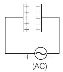
$$ \begin{aligned} \text{Power applied to a circuit is} \quad P_av & =V_rms I_rms \cos \phi \\ \text{For capactive circuit,} \quad \phi & =90^{\circ} \\ \Rightarrow \quad \cos \phi & =0 \\ \Rightarrow \quad P_{\mathrm{av}} & =\text { Power delivered }=0 \end{aligned} $$
-
(a) the maximum voltage between plates is $220 \mathrm{~V}$: This statement is incorrect because the maximum voltage between the plates of a capacitor in an AC circuit is not necessarily equal to the RMS voltage of the AC source. The RMS voltage is a measure of the effective voltage, not the peak voltage. The peak voltage ( V_{\text{peak}} ) is actually ( V_{\text{RMS}} \times \sqrt{2} ), which is higher than the RMS voltage.
-
(b) the current is in phase with the applied voltage: This statement is incorrect because in a purely capacitive AC circuit, the current leads the voltage by 90 degrees. This means that the current reaches its maximum value a quarter cycle before the voltage does, so they are not in phase.
13. he line that draws power supply to your house from street has
(a) zero average current
(b) $220 \mathrm{~V}$ average voltage
(c) voltage and current out of phase by $90^{\circ}$
(d) voltage and current possibly differing in phase $\phi$ such that $|\phi|<\frac{\pi}{2}$
Show Answer
Answer
$(a, d)$
For house hold supplies, AC currents are used which are having zero average value over a cycle.
The line is having some resistance so power factor $\cos \phi=\frac{R}{Z} \neq 0$
so,
$$ \phi \neq \pi / 2 \Rightarrow \phi,<\pi / 2 $$
i.e., phase lies between 0 and $\pi / 2$.
-
(b) $220 \mathrm{~V}$ average voltage: The voltage supplied to households is typically an RMS (root mean square) value, not an average value. The RMS value of 220V is a measure of the effective voltage, not the average voltage over a cycle.
-
(c) voltage and current out of phase by $90^{\circ}$: In a typical household power supply, the voltage and current are not out of phase by $90^{\circ}$. If they were, it would imply a purely reactive load (either purely inductive or purely capacitive), which is not the case for household appliances that have both resistive and reactive components.
Very Short Answer Type Questions
14. If a $L-C$ circuit is considered analogous to a harmonically oscillating springblock system, which energy of the $L-C$ circuit would be analogous to potential energy and which one analogous to kinetic energy?
Show Answer
Answer
If we consider a $L-C$ circuit analogous to a harmonically oscillating springblock system. The electrostatic energy $\frac{1}{2} C V^{2}$ is analogous to potential energy and energy associated with moving charges (current) that is magnetic energy $\frac{1}{2} L I^{2}$ is analogous to kinetic energy.
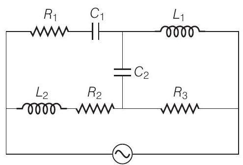
15. Draw the effective equivalent circuit of the circuit shown in figure, at very high frequencies and find the effective impedance.
Show Answer
Thinking Process
The component with infinite resistance will be considered as open circuit and the component with zero resistance will be considered as short circuited.
Answer
We know that inductive reactance $X_{L}=2 \pi f L$
and capacitive reactance $X_{C}=\frac{1}{2 \pi f C}$
For very high frequencies $(f \rightarrow \infty), X_{L} \rightarrow \infty$ and $X_{C} \rightarrow 0$
When reactance of a circuit is infinite it will be considered as open circuit. When reactance of a circuit is zero it will be considered as short circuited.
So, $C_{1}, C_{2} \rightarrow$ shorted and $L_{1}, L_{2} \rightarrow$ opened.
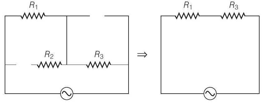
So, effective impedance $=R_{\text {eq }}=R_{1}+R_{3}$
16. Study the circuits (a) and (b) shown in figure and answer the following questions.
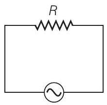
(a)
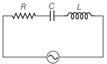
(b)
(a) Under which conditions would the rms currents in the two circuits be the same?
(b) Can the rms current in circuit (b) be larger than that in (a)?
Show Answer
Answer
Let,
$$ \begin{aligned} & \left(I_{\mathrm{rms}}\right) a=\text { rms current in circuit }(\mathrm{a}) \\ & \left(I_{\mathrm{rms}}\right) b=\text { rms current in circuit }(\mathrm{b}) \\ & \left(I_{\mathrm{rms}}\right) a=\frac{V_{\mathrm{rms}}}{R}=\frac{V}{R} \\ & \left(I_{\mathrm{rms}}\right) b=\frac{V_{\mathrm{rms}}}{Z}=\frac{V}{\sqrt{R^{2}+\left(X_{L}-X_{C}\right)^{2}}} \end{aligned} $$
(a) When
$$ \begin{aligned} \left(I_{\mathrm{rms}}\right) a & =\left(I_{\mathrm{rms}}\right) b \\ R & =\sqrt{R^{2}+\left(X_{L}-X_{C}\right)^{2}} \end{aligned} $$
$$ \Rightarrow \quad X_{L}=X_{C} \text {, resonance condition } $$
(b) As $Z \geq R$
$$ \begin{array}{rlrl} \Rightarrow \frac{\left(I_{\mathrm{rms}}\right) a}{\left(I_{\mathrm{rms}}\right) b} & =\frac{\sqrt{R^{2}+\left(X_{L}-X_{C}\right)^{2}}}{R} \\ =\frac{Z}{R} \geq 1 \\ \Rightarrow \left(I_{\mathrm{rms}}\right) a & \geq\left(I_{\mathrm{rms}}\right) b \end{array} $$
No, the rms current in circuit (b), cannot be larger than that in (a).
17. an the instantaneous power output of an $A C$ source ever be negative? Can the average power output be negative?
Show Answer
Answer
Let the applied emf
and current developed is
$$ E=E_{0} \sin (\omega t) $$
and cure
$$ I=I_{0} \sin (\omega t \pm \phi) $$
Instantaneous power output of the $\mathrm{AC}$ source
$$ \begin{aligned} P & =E I=\left(E_{0} \sin \omega t\right) \\ & =E_{0} I_{0} \sin \omega t \cdot \sin (\omega t+\phi) \\ & =\frac{E_{0} I_{0}}{2}[\cos \phi-\cos (2 \omega t+\phi)] \end{aligned} $$
Average power
$$ \begin{aligned} P_{\mathrm{av}}= & \frac{V_{0}}{\sqrt{2}} \frac{I_{0}}{\sqrt{2}} \cos \phi \\ & =V_{\mathrm{rms}} I_{\mathrm{rms}} \cos \phi \end{aligned} $$
where $\phi$ is the phase difference.
Clearly, from Eq. (i)
when
$$ \begin{gathered} \cos \phi<\cos (2 \omega t+\phi) \\ P<0 \end{gathered} $$
Yes, the instantaneous power output of an $A C$ source can be negative From Eq. (ii)
$$ \begin{aligned} P_{\mathrm{av}} & >0 \\ \cos \phi & =\frac{R}{Z}>0 \end{aligned} $$
Because
No, the average power output of an $A C$ source cannot be negative.
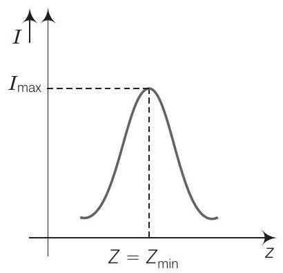
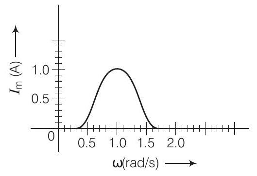
18. In series $L C R$ circuit, the plot of $I_{\max }$ versus $\omega$ is shown in figure. Find the bandwidth and mark in the figure.
Show Answer
Answer
Consider the diagram .
Bandwidth $=\omega_{2}-\omega_{1}$
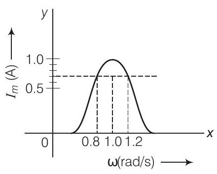
where $\omega_{1}$ and $\omega_{2}$ corresponds to frequencies at which magnitude of current is $\frac{1}{\sqrt{2}}$ times of maximum value.
$$ I_{\mathrm{rms}}=\frac{I_{\max }}{\sqrt{2}}=\frac{1}{\sqrt{2}} \approx 0.7 \mathrm{~A} $$
Clearly from the diagram, the corresponding frequencies are $0.8 \mathrm{rad} / \mathrm{s}$ and $1.2 \mathrm{rad} / \mathrm{s}$.
$$ \Delta \omega=\text { Bandwidth }=1 \cdot 2-0.8=0.4 \mathrm{rad} / \mathrm{s} $$
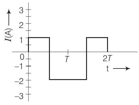
19. The alternating current in a circuit is described by the graph shown in figure. Show rms current in this graph.
Show Answer
Answer
$I_{\mathrm{rms}}=\mathrm{rms}$ current
$$ =\sqrt{\frac{1^{2}+2^{2}}{2}}=\sqrt{\frac{5}{2}}=1.58 \mathrm{~A} \approx 1.6 \mathrm{~A} $$
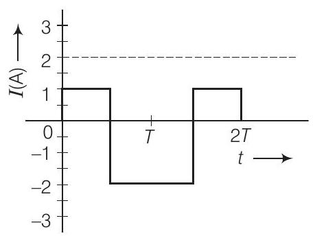
The rms value of the current $\left(I_{\mathrm{rms}}\right)=1.6 \mathrm{~A}$ is indicated in the graph.
20. How does the sign of the phase angle $\phi$, by which the supply voltage leads the current in an $L-C-R$ series circuit, change as the supply frequency is gradually increased from very low to very high values.
Show Answer
Answer
The phase angle $(\phi)$ by which voltage leads the current in $L-C-R$ series circuit is given by
$$ \begin{array}{ll} \tan \phi=\frac{X_{L}-X_{C}}{R}=\frac{2 \pi \nu L-\frac{1}{2 \pi \nu C}}{R} & \\ \tan \phi<0\left(\text { for } \nu<\nu_{0}\right) & \text { for } \nu=\nu_{0}=\frac{1}{2 \pi \sqrt{2 C}} \end{array} $$
Short Answer Type Questions
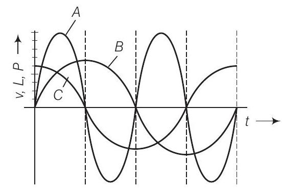
21. A device ’ $X$ ’ is connected to an $A C$ source. The variation of voltage, current and power in one complete cycle is shown in figure.
(a) Which curve shows power consumption over a full cycle?
(b) What is the average power consumption over a cycle?
(c) Identify the device $X$.
Show Answer
Answer
(a) We know that Power $=P=V I$
that is curve of power will be having maximum amplitude, equals to multiplication of amplitudes of voltage $(V)$ and current $(I)$ curve. So, the curve will be represented by $A$.
(b) As shown by shaded area in the diagram, the full cycle of the graph consists of one positive and one negative symmetrical area.
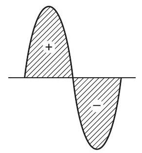
Hence, average power over a cycle is zero.
(c) As the average power is zero, hence the device may be inductor $(L)$ or capacitor $(C)$ or the series combination of $L$ and $C$.
22. Both alternating current and direct current are measured in amperes. But how is the ampere defined for an alternating current?
Show Answer
Answer
For a Direct Current (DC),
$$ 1 \text { ampere }=1 \text { coulomb/sec } $$
An $A C$ current changes direction with the source frequency and the attractive force would average to zero. Thus, the AC ampere must be defined in terms of some property that is independent of the direction of current.
Joule’s heating effect is such property and hence it is used to define rms value of AC.
23. A coil of $0.01 \mathrm{H}$ inductance and $1 \Omega$ resistance is connected to $200 \mathrm{~V}$, $50 \mathrm{~Hz} \mathrm{AC}$ supply. Find the impedance of the circuit and time lag between maximum alternating voltage and current.
Show Answer
Answer
Given, inductance $L=0.01 \mathrm{H}$ resistance $R=1 \Omega$, voltage $(V)=200 \mathrm{~V}$
and frequency $(f)=50 \mathrm{~Hz}$.
Impedance of the circuit $\quad Z=\sqrt{R^{2}+X_{L}^{2}}=\sqrt{R^{2}+(2 \pi f L)^{2}}$ $$=\sqrt{1^{2}+(2 \times 3.14 \times 50 \times 0.01)^{2}}$$
$$ or \quad Z=\sqrt{10.86}=3.3 \Omega $$
$$ \begin{aligned} \tan \phi & =\frac{\omega L}{R}=\frac{2 \pi f L}{R}=\frac{2 \times 3.14 \times 50 \times 0.01}{1}=3.14 \\ \phi & =\tan ^{-1}(3.14) \approx 72^{\circ} \\ \text{Phase difference} \qquad \phi & =\frac{72 \times \pi}{180} \mathrm{rad} . \end{aligned} $$
Time lag between alternating voltage and current
$$ \Delta t=\frac{\phi}{\omega}=\frac{72 \pi}{180 \times 2 \pi \times 50}=\frac{1}{250} \mathrm{~s} $$
24. A $60 \mathrm{~W}$ load is connected to the secondary of a transformer whose primary draws line voltage. If a current of $0.54 \mathrm{~A}$ flows in the load, what is the current in the primary coil? Comment on the type of tansformer being used.
Show Answer
Answer
Given, $P_{S}=60 \mathrm{~W}, I_{S}=0.54 \mathrm{~A}$
Current in the primary $I_{D}=$ ?
Taking line voltage as $220 \mathrm{~V}$.
We can write Since,
$$ \begin{array}{ll} \Rightarrow & P_{L}=60 \mathrm{~W}, I_{L}=0.54 \mathrm{~A} \\ \Rightarrow & V_{L}=\frac{60}{0.54}=110 \mathrm{~V} . \end{array} $$
Voltage in the secondary $\left(E_{S}\right)$ is less than voltage in the primary $\left(E_{p}\right)$.
Hence, the transformer is step down transformer.
Since, the transformation ratio
Substituting the values,
On solving
$$ \begin{aligned} r & =\frac{V_{s}}{V_{p}}=\frac{I_{p}}{I_{s}} \\ \frac{110 \mathrm{~V}}{220 \mathrm{~V}} & =\frac{I_{p}}{0.54 \mathrm{~A}} \\ I_{p} & =0.27 \mathrm{~A} \end{aligned} $$
25. Explain why the reactance provided by a capacitor to an alternating current decreases with increasing frequency.
Show Answer
Answer
A capacitor does not allow flow of direct current through it as the resistance across the gap is infinite. When an alternating voltage is applied across the capacitor plates, the plates are alternately charged and discharged. The current through the capacitor is a result of this changing voltage (or charge).
Thus, a capacitor will pass more current through it if the voltage is changing at a faster rate, i.e. if the frequency of supply is higher. This implies that the reactance offered by a capacitor is less with increasing frequency.
Mathematically, the reactance can be written as $X_{C}=\frac{1}{\omega C}$.
26. Explain why the reactance offered by an inductor increases with increasing frequency of an alternating voltage.
Show Answer
Answer
An inductor opposes flow of current through it by developing a back emf according to Lenz’s law. The induced voltage has a polarity so as to maintain the current at its present value. If the current is decreasing, the polarity of the induced emf will be so as to increase the current and vice -versa.
Since, the induced emf is proportional to the rate of change of current, it will provide greater reactance to the flow of current if the rate of change is faster, i.e., if the frequency is higher. The reactance of an inductor, therefore, is proportional to the frequency. Mathematically, the reactance offered by the inductor is given by $X_{L}=\omega L$.
Long Answer Type Questions
27. An electrical device draws $2 \mathrm{~kW}$ power from $\mathrm{AC}$ mains (voltage $223 \mathrm{~V}$ (rms) $=\sqrt{50000} \mathrm{~V}$ ). The current differs (lags) in phase by $\phi \tan \phi=\frac{-3}{4}$ as compared to voltage. Find (a) $R_{r}$ (b) $X_{C}-X_{L}$ and (c) $I_{M}$. Another device has twice the values for $R, X_{C}$ and $X_{L}$. How are the answers affected?
Show Answer
Thinking Process
We have to apply the formula for phase relation, net reactance as well as instantaneous power associate with the circuit in terms of voltage and current.
Answer
Given, power drawn $=P=2 \mathrm{~kW}=2000 \mathrm{~W}$
$$ \begin{array}{rlrl} \tan \phi =-\frac{3}{4}, I_{M}=I_{0}=?, R=?, X_{C}-X_{L}=? \\ V_{\mathrm{rms}} =V=223 \mathrm{~V} \\ \text { Power } P =\frac{V^{2}}{Z} \\ \Rightarrow Z =\frac{V^{2}}{P}=\frac{223 \times 223}{2 \times 10^{3}}=25 \\ \text { Impedance } Z =25 \Omega \\ \text { Impedance } Z =\sqrt{R^{2}+\left(X_{L}-X_{C}\right)^{2}} \\ \Rightarrow \qquad 25 =\sqrt{R^{2}+\left(X_{L}-X_{C}\right)^{2}} \\ or \qquad 625 =R^{2}+\left(X_{L}-X_{C}\right)^{2} \\ \text{Again,}\qquad \tan \phi =\frac{X_{L}-X_{C}}{R}=\frac{3}{4} \\ or \qquad X_{L}-X_{C} =\frac{3 R}{4} \end{array} $$
From Eq. (ii), we put $X_{L}-X_{C}=\frac{3 R}{4}$ in Eq. (i), we get
$$ \begin{aligned} & 625=R^{2}+\frac{3 R}{4}^{2}=R^{2}+\frac{9 R^{2}}{16} \\ or \qquad & 625=\frac{25 R^{2}}{16} \end{aligned} $$
(a) Resistance $R=\sqrt{25 \times 16}=\sqrt{400}=20 \Omega$
(b) $X_{L}-X_{C}=\frac{3 R}{4}=\frac{3}{4} \times 20=15 \Omega$
(c) Main current $I_{M}=\sqrt{2} I=\sqrt{2} \frac{V}{Z}=\frac{223}{25} \times \sqrt{2}=12.6 \mathrm{~A}$
As $R, X_{C}, X_{L}$ are all doubled, $\tan \phi$ does not change. $Z$ is doubled, current is halved. So, power is also halved.
28. $\mathrm{MW}$ power is to be delivered from a power station to a town $10 \mathrm{~km}$ away. One uses a pair of $\mathrm{Cu}$ wires of radius $0.5 \mathrm{~cm}$ for this purpose. Calculate the fraction of ohmic losses to power transmitted if
(i) power is transmitted at $220 \mathrm{~V}$. Comment on the feasibility of doing this.
(ii) a step-up transformer is used to boost the voltage to $11000 \mathrm{~V}$, power transmitted, then a step-down transformer is used to bring voltage to $220 \mathrm{~V}$.
$$ \left(\rho_{c u}=1.7 \times 10^{-8} \text { SI unit }\right) $$
Show Answer
Answer
(i) The town is $10 \mathrm{~km}$ away, length of pair of Cu wires used, $L=20 \mathrm{~km}=20000 \mathrm{~m}$.
Resistance of Cu wires,
$$ \begin{aligned} R & =\frac{l}{A}=\frac{l}{\pi(r)^{2}} \\ & =\frac{1.7 \times 10^{-8} \times 20000}{3.14\left(0.5 \times 10^{-2}\right)^{2}}=4 \Omega \end{aligned} $$
$I$ at $220 \mathrm{~V}$
$$ \begin{aligned} V I & =10^{6} \mathrm{~W} ; I=\frac{10^{6}}{220}=0.45 \times 10^{4} \mathrm{~A} \\ R I^{2} & =\text { power loss } \\ & =4 \times(0.45)^{2} \times 10^{8} \mathrm{~W} \\ & >10^{6} \mathrm{~W} \end{aligned} $$
Therefore, this method cannot be used for transmission.
(ii) When power $P=10^{6} \mathrm{~W}$ is transmitted at $11000 \mathrm{~V}$.
$$ \begin{aligned} V^{\prime} I^{\prime} & =10^{6} \mathrm{~W}=11000 I^{\prime} \\ \text { Current drawn, } I^{\prime} & =\frac{1}{1.1} \times 10^{2} \\ \text { Power loss } & =R I^{2}=\frac{1}{1.21} \times 4 \times 10^{4} \\ & =3.3 \times 10^{4} \mathrm{~W} \\ \text { Fraction of power loss } & =\frac{3.3 \times 10^{4}}{10^{6}}=3.3 % \end{aligned} $$
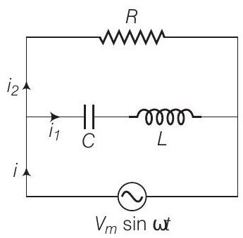
29. Consider the $L-C-R$ circuit shown in figure. Find the net current $i$ and the phase of $i$. Show that $i=\frac{V}{Z}$. Find the impedance $Z$ for this circuit.
Show Answer
Thinking Process
The circuit consists of inductor (L) and capacitor (C) connected in series and the combination is connected parallel with a resistance $R$. Due to this combination there is oscillation of electromagnetic energy.
Answer
In the given figure $i$ is the total current from the source. It is divided into two parts $i_{1}$ through $R$ and $i_{2}$ through series combination of $C$ and $L$.
So, we can write $i=i_{1}+i_{2}$ As, $V_{m} \sin \omega t=R i_{1}$ $\Rightarrow$
$$ i_{1}=\frac{V_{m} \sin \omega t}{R} $$
[from the circuit diagram]
If $q_{2}$ is charge on the capacitor at any time $t$, then for series combination of $C$ and $L$.
Applying KVL in the Lower circuit as shown,
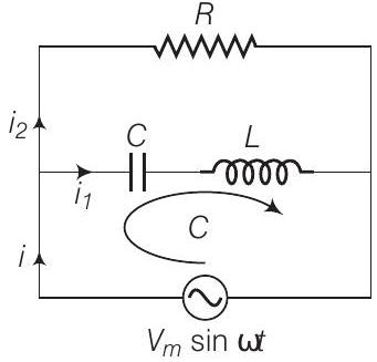
$$ \begin{array}{rlrl} \frac{q_{2}}{C}+\frac{L d i_{2}}{d t}-V_{m} \sin \omega t=0 \\ \Rightarrow \frac{q_{2}}{C}+\frac{L d_{2} q_{2}}{d t^{2}} =V_{m} \sin \omega t \\ \text { Let } \therefore \frac{d q_{2}}{d t} =q_{m} \omega \cos (\omega t+\phi) \\ \Rightarrow \frac{d^{2} q_{2}}{d t^{2}} =-q_{m} \omega^{2} \sin (\omega t+\phi) \end{array} $$
$$ \Rightarrow \quad \frac{q_{2}}{C}+\frac{L d_{2} q_{2}}{d t^{2}}=V_{m} \sin \omega t \quad \because i_{2}=\frac{d q_{2}}{d t} $$
Now putting these values in Eq. (ii), we get
$$ q_{m} \frac{1}{C}+L\left(-\omega^{2}\right) \sin (\omega t+\phi)=V_{m} \sin \omega t $$
If $\phi=0$ and $\frac{1}{C}-L \omega^{2}>0$,
then
$$ q_{m}=\frac{V_{m}}{\frac{1}{C}-L \omega^{2}} $$
From Eq. (iii),
$$ \begin{aligned} i_{2} =\frac{d q_{2}}{d t}=\omega q_{m} \cos (\omega t+\phi) \\ i_{2} =\frac{\omega V_{m} \cos (\omega t+\phi)}{\frac{1}{C}-L \omega^{2}} \\ \text { Taking } \phi =0 ; i_{2}=\frac{V_{m} \cos (\omega t)}{\frac{1}{\omega C}-L \omega} \end{aligned} $$
using Eq. (iv),
From Eqs. (i) and (v), we find that $i_{1}$ and $i_{2}$ are out of phase by $\frac{\pi}{2}$.
Now,
$$ i_{1}+i_{2}=\frac{V_{m} \sin \omega t}{R}+\frac{V_{m} \cos \omega t}{\frac{1}{\omega C}-L \omega} $$
Put
$$ \frac{V_{m}}{R}=A=C \cos \phi \text { and } \frac{V_{m}}{\frac{1}{\omega C}-L \omega}=B=C \sin \phi $$
$\therefore \quad i_{1}+i_{2}=C \cos \phi \sin \omega t+C \sin \phi \cos \omega t$
$$ =C \sin (\omega t+\phi) $$
where
$$ C=\sqrt{A^{2}+B^{2}} $$
and
$$ \phi=\tan ^{-1} \frac{B}{A} C=\frac{V_{m}^{2}}{R^{2}}+\frac{V_{m}^{2}}{\frac{1}{\omega C}-L \omega} $$
and
$$ \phi=\tan ^{-1} \frac{R}{\frac{1}{\omega C}-L \omega} $$
Hence,
$$ i=i_{1}+i_{2}=\frac{V_{m}^{2}}{R^{2}}+\frac{V_{m}^{2}}{\frac{1}{\omega C}-L \omega} \sin (\omega t+\phi) $$
or
$$ \frac{i}{V_{m}}=\frac{1}{Z}=\frac{1}{R^{2}}+\frac{1}{\frac{1}{\omega C}-L \omega^{2}} $$
This is the expression for impedance $Z$ of the circuit.
Note In this problem, we should not apply the formulae of L-C-R series circuit directly.
30. For a $L-C-R$ circuit driven at frequency $\omega$ the equation reads
$$ L \frac{d i}{d t}+R i+\frac{q}{C}=V_{i}=V_{m} \sin \omega t $$
(a) Multiply the equation by $i$ and simplify where possible.
(b) Interpret each term physically.
(c) Cast the equation in the form of a conservation of energy statement.
(d) Intergrate the equation over one cycle to find that the phase difference between $V$ and $i$ must be acute.
Show Answer
Thinking Process
Apply KVL for the given L-C-R series circuit and find the required relations. Also find energy loss through the resistors to know net loss of energy through the circuit.
Answer
Consider the $L-C-R$ circuit. Applying KVL for the loop, we can write
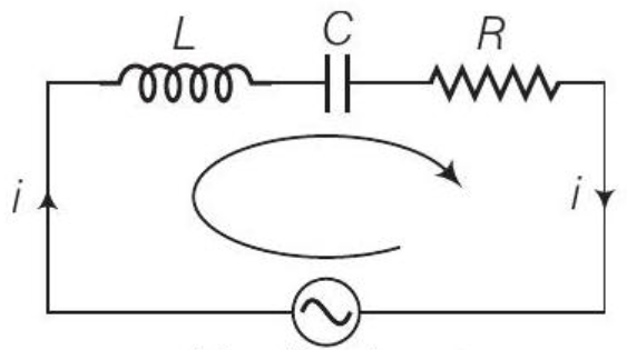
$\begin{gathered}V=V_m \sin \omega t \\ L \frac{d i}{d t}+\frac{q}{C}+i R=V_m \sin \omega t\end{gathered}$
Multiplying both sides by $i$, we get
$$ L i \frac{d i}{d t}+\frac{q}{C} i+i^{2} R=\left(V_{m} i\right) \sin \omega t=V i $$
where
$$ \begin{aligned} L i \frac{d i}{d t}=\frac{d}{d t} & \frac{1}{2} L i^{2}=\text { rate of change of energy stored in an inductor. } \\ R i^{2} & =\text { joule heating loss } \\ \frac{q}{C} i=\frac{d}{d t} & \frac{q^{2}}{2 C}=\text { rate of change of energy stored in the capacitor. } \end{aligned} $$
$V i=$ rate at which driving force pours in energy. It goes into (i) ohmic loss and (ii) increase of stored energy.
Hence Eq. (ii) is in the form of conservation of energy statement. Integrating both sides of Eq. (ii) with respect to time over one full cycle $(0 \rightarrow T)$ we may write
$$ \begin{array}{r} \int_{0}^{T} \frac{d}{d t} \frac{1}{2} L i^{2}+\frac{q^{2}}{2 C} d t+\int_{0}^{T} R i^{2} d t=\int_{0}^{T} V i d t \\ \Rightarrow 0+(+v e)=\int_{0}^{T} V i d t \\ \Rightarrow \int_{0}^{T} V i d t>0 \text { if phase difference between } V \text { and } i \text { is a constant and acute angle. } \end{array} $$
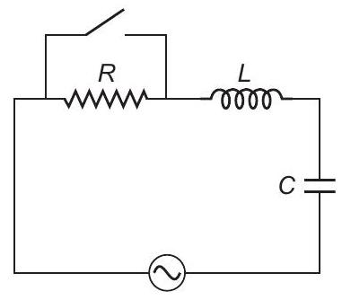
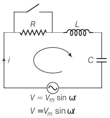
31. In the $L-C-R$ circuit, shown in figure the $A C$ driving voltage is $V=V_{m}$ $\sin \omega t$.
(a) Write down the equation of motion for $q(t)$.
(b) At $t=t_{0}$, the voltage source stops and $R$ is short circuited. Now write down how much energy is stored in each of $L$ and $C$.
(c) Describe subsequent motion of charges.
K Thinking Process
We have to apply KVL write the equations in the form of current and charge double differentiate the equation with respect to time and find the required relations.
Show Answer
Answer
(a) Consider the R-L-C circuit shown in the adjacent diagram.
Given Let current at any instant be $i$
Applying KVL in the given circuit
$$ i R+L \frac{d i}{d t}+\frac{q}{C}-V_{m} \sin \omega t=0 $$
Now, we can write
$$ i=\frac{d q}{d t} \Rightarrow \frac{d i}{d t}=\frac{d^{2} q}{d t^{2}} $$
From Eq. (i)
$$ \frac{d q}{d t} R+L \frac{d^{2} q}{d t^{2}}+\frac{q}{C}=V_{m} \sin \omega t $$
$$ \Rightarrow \quad L \frac{d^{2} q}{d t^{2}}+R \frac{d q}{d t}+\frac{q}{C}=V_{m} \sin \omega t $$
This is the required equation of variation (motion) of charge. (b) Let $\quad q=q_{m} \sin (\omega t+\phi)=-q_{m} \cos (\omega t+\phi)$
$$ \begin{aligned} i & =i_{m} \sin (\omega t+\phi)=q_{m} \omega \sin (\omega t+\phi) \\ i_{m} & =\frac{V_{m}}{Z}=\frac{V_{m}}{\sqrt{R^{2}+\left(X_{C}-X_{L}\right)^{2}}} \\ \phi & =\tan ^{-1} \frac{X_{C}-X_{L}}{R} \end{aligned} $$
When $R$ is short circuited at $t=t_{0}$, energy is stored in $L$ and $C$.
and
$$ \begin{aligned} U_{L} & =\frac{1}{2} L i^{2}=\frac{1}{2} L \frac{V_{m}}{\sqrt{\left(R^{2}+X_{C}-X_{L}\right)^{2}}} \sin ^{2}\left(\omega t_{0}+\phi\right) \\ U_{C} & =\frac{1}{2} \times \frac{q^{2}}{C}=\frac{1}{2 C}\left[q^{2} m \cos ^{2}\left(\omega t_{0}+\phi\right)\right] \\ & =\frac{1}{2 C} \frac{V_{m}}{\sqrt{R^{2}+\left(X_{C}-X_{L}\right)^{2}}} \\ & =\frac{1}{2 C} \times \frac{i_{m}}{\omega} \cos ^{2}\left(\omega t_{0}+\phi\right) \\ & =\frac{i^{2} m}{2 C \omega^{2}} \cos ^{2}\left(\omega t_{0}+\phi\right) \\ & =\frac{1}{2 C} \frac{V_{m}}{\sqrt{R^{2}+\left(X_{C}-X_{L}\right)^{2}}} \frac{\cos ^{2}\left(\omega t_{0}+\phi\right)}{\omega^{2}} \quad\left[\because i_{m}=q_{m} \omega\right] \\ & =\frac{1}{2 C \omega^{2}} \frac{V_{m}}{\sqrt{R^{2}+\left(X_{C}-X_{L}\right)^{2}}} \cos ^{2}\left(\omega t_{0}+\phi\right) \end{aligned} $$
(c) When $R$ is short circuited, the circuit becomes an $L-C$ oscillator. The capacitor will go on discharging and all energy will go to $L$ and back and forth. Hence, there is oscillation of energy from electrostatic to magnetic and magnetic to electrostatic.


