Alternating Current
Exercises
7.1 A $100 \Omega$ resistor is connected to a $220 \mathrm{~V}, 50 \mathrm{~Hz}$ ac supply.
(a) What is the rms value of current in the circuit?
(b) What is the net power consumed over a full cycle?
Show Answer
Answer
Resistance of the resistor, $R=100 \Omega$
Supply voltage, $V=220 \mathrm{~V}$
Frequency, $v=50 \mathrm{~Hz}$
(a) The rms value of current in the circuit is given as:
$$ \begin{aligned} I & =\frac{V}{R} \\ & =\frac{220}{100}=2.20 \mathrm{~A} \end{aligned} $$
(b) The net power consumed over a full cycle is given as:
$$ P=V I $$
$=220 \times 2.2=484 \mathrm{~W}$
7.2 (a) The peak voltage of an ac supply is $300 \mathrm{~V}$. What is the rms voltage?
(b) The rms value of current in an ac circuit is $10 \mathrm{~A}$. What is the peak current?
Show Answer
Answer
(a) Peak voltage of the ac supply, $V_{0}=300 \mathrm{~V}$
Rms voltage is given as:
$$ \begin{aligned} V & =\frac{V_{0}}{\sqrt{2}} \\ & =\frac{300}{\sqrt{2}}=212.1 \mathrm{~V} \end{aligned} $$
(b) Therms value of current is given as:
$I=10 \mathrm{~A}$
Now, peak current is given as:
$$ \begin{aligned} I_{0} & =\sqrt{2} I \\ & =10 \sqrt{2}=14.1 \mathrm{~A} \end{aligned} $$
7.3 A $44 \mathrm{mH}$ inductor is connected to $220 \mathrm{~V}, 50 \mathrm{~Hz}$ ac supply. Determine the rms value of the current in the circuit.
Show Answer
Answer
Inductance of inductor, $L=44 \mathrm{mH}=44 \times 10^{-3} \mathrm{H}$
Supply voltage, $V=220 \mathrm{~V}$
Frequency, $v=50 \mathrm{~Hz}$
Angular frequency, $\omega=2 \pi v$
Inductive reactance, $X_{\mathrm{L}}=\omega L=2 \pi \nu L=2 \pi \times 50 \times 44 \times 10^{-3} \Omega$
Rms value of current is given as:
$$ \begin{aligned} I & =\frac{v}{X_{\mathrm{L}}} \\ & =\frac{220}{2 \pi \times 50 \times 44 \times 10^{-3}}=15.92 \mathrm{~A} \end{aligned} $$
Hence, the rms value of current in the circuit is $15.92 \mathrm{~A}$.
7.4 A $60 \mu \mathrm{F}$ capacitor is connected to a $110 \mathrm{~V}, 60 \mathrm{~Hz}$ ac supply. Determine the rms value of the current in the circuit.
Show Answer
Answer
Capacitance of capacitor, $C=60 \mu \mathrm{F}=60 \times 10^{-6} \mathrm{~F}$
Supply voltage, $V=110 \mathrm{~V}$
Frequency, $v=60 \mathrm{~Hz}$
Angular frequency, $\omega=2 \pi v$
Capacitive reactance $X_{\mathrm{c}}=\frac{1}{\omega C}$
$=\frac{1}{2 \pi v C}$
$=\frac{1}{2 \times 3.14 \times 60 \times 60 \times 10^{-6}} \Omega^{-1}$
Rms value of current is given as:
$$ \begin{aligned} I & =\frac{v}{X_{\mathrm{c}}} \\ & =110 \times 2 \times 3.14 \times 60 \times 10^{-6} \times 60=2.49 \mathrm{~A} \end{aligned} $$
Hence, the rms value of current is $2.49 \mathrm{~A}$.
7.5 In Exercises 7.3 and 7.4, what is the net power absorbed by each circuit over a complete cycle. Explain your answer.
Show Answer
Answer
In the inductive circuit,
Rms value of current, $I=15.92 \mathrm{~A}$
Rms value of voltage, $V=220 \mathrm{~V}$
Hence, the net power absorbed can be obtained by the relation,
$P=V I \cos \Phi$
Where,
$\Phi=$ Phase difference between $V$ and $I$
For a pure inductive circuit, the phase difference between alternating voltage and current is $90^{\circ}$ i.e., $\Phi=90^{\circ}$.
Hence, $P=0$ i.e., the net power is zero.
In the capacitive circuit,
Rms value of current, $I=2.49$ A
Rms value of voltage, $V=110 \mathrm{~V}$
Hence, the net power absorbed can ve obtained as:
$P=V I \operatorname{Cos} \Phi$
For a pure capacitive circuit, the phase difference between alternating voltage and current is $90^{\circ}$ i.e., $\Phi=90^{\circ}$.
Hence, $P=0$ i.e., the net power is zero.
7.6 A charged $30 \mu \mathrm{F}$ capacitor is connected to a $27 \mathrm{mH}$ inductor. What is the angular frequency of free oscillations of the circuit?
Show Answer
Answer
Capacitance, $C=30 \mu \mathrm{F}=30 \times 10^{-6} \mathrm{~F}$
Inductance, $L=27 \mathrm{mH}=27 \times 10^{-3} \mathrm{H}$
Angular frequency is given as:
$$ \begin{aligned} \omega_{r} & =\frac{1}{\sqrt{L C}} \\ & =\frac{1}{\sqrt{27 \times 10^{-3} \times 30 \times 10^{-6}}}=\frac{1}{9 \times 10^{-4}}=1.11 \times 10^{3} \mathrm{rad} / \mathrm{s} \end{aligned} $$
Hence, the angular frequency of free oscillations of the circuit is $1.11 \times 10^{3} \mathrm{rad} / \mathrm{s}$.
7.7 A series $L C R$ circuit with $R=20 \Omega, L=1.5 \mathrm{H}$ and $C=35 \mu \mathrm{F}$ is connected to a variable-frequency $200 \mathrm{~V}$ ac supply. When the frequency of the supply equals the natural frequency of the circuit, what is the average power transferred to the circuit in one complete cycle?
Show Answer
Answer
At resonance, the frequency of the supply power equals the natural frequency of the given LCR circuit.
Resistance, $R=20 \Omega$
Inductance, $L=1.5 \mathrm{H}$
Capacitance, $C=35 \mu \mathrm{F}=30 \times 10^{-6} \mathrm{~F}$
AC supply voltage to the $L C R$ circuit, $V=200 \mathrm{~V}$
Impedance of the circuit is given by the relation,
$Z=\sqrt{R^{2}+\left(\omega L-\frac{1}{\omega C}\right)^{2}}$
At resonance, $\omega L=\frac{1}{\omega C}$
$\therefore Z=R=20 \Omega$
Current in the circuit can be calculated as:
$$ \begin{aligned} I & =\frac{V}{Z} \\ & =\frac{200}{20}=10 \mathrm{~A} \end{aligned} $$
Hence, the average power transferred to the circuit in one complete cycle $=V I$
$=200 \times 10=2000 \mathrm{~W}$.
7.8 Figure 7.17 shows a series $L C R$ circuit connected to a variable frequency $230 \mathrm{~V}$ source. $L=5.0 \mathrm{H}, C=80 \mu \mathrm{F}, R=40 \Omega$.
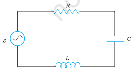
FIGURE 7.17
(a) Determine the source frequency which drives the circuit in resonance.
(b) Obtain the impedance of the circuit and the amplitude of current at the resonating frequency.
(c) Determine the rms potential drops across the three elements of the circuit. Show that the potential drop across the $L C$ combination is zero at the resonating frequency.
Show Answer
Answer
Inductance of the inductor, $L=5.0 \mathrm{H}$ Capacitance of the capacitor, $C=80 \mu \mathrm{H}=80 \times 10^{-6} \mathrm{~F}$ Resistance of the resistor, $R=40 \Omega$ Potential of the variable voltage source, $V=230 \mathrm{~V}$ (a) Resonance angular frequency is given as: $$ \begin{aligned} \omega_R & =\frac{1}{\sqrt{L C}} \ & =\frac{1}{\sqrt{5 \times 80 \times 10^{-6}}}=\frac{10^3}{20}=50 \mathrm{rad} / \mathrm{s} \end{aligned} $$
Hence, the circuit will come in resonance for a source frequency of $50 \mathrm{rad} / \mathrm{s}$.
(b) Impedance of the circuit is given by the relation, $$ Z=\sqrt{R^2+\left(\omega L-\frac{1}{\omega C}\right)^2} $$
At resonance, $$ \begin{aligned} & \omega L=\frac{1}{\omega C} \ & \therefore Z=R=40 \Omega \end{aligned} $$
Amplitude of the current at the resonating frequency is given as: $I_0=\frac{V_0}{Z}$ Where, $$ \begin{aligned} V_0 & =\text { Peak voltage } \ & =\sqrt{2} \mathrm{~V} \ \therefore I_0 & =\frac{\sqrt{2} \mathrm{~V}}{Z} \ & =\frac{\sqrt{2} \times 230}{40}=8.13 \mathrm{~A} \end{aligned} $$
Hence, at resonance, the impedance of the circuit is $40 \Omega$ and the amplitude of the current is $8.13 \mathrm{~A}$.
(c) Rms potential drop across the inductor, $$ \left(V_L\right)_{\text {rms }}=I \times \omega_R L $$
Where, $I=$ rms current $$ \begin{aligned} & =\frac{I_0}{\sqrt{2}}=\frac{\sqrt{2} V}{\sqrt{2} Z}=\frac{230}{40} \mathrm{~A} \ & \therefore\left(V_L\right)_{\text {rms }}=\frac{230}{40} \times 50 \times 5=1437.5 \mathrm{~V} \end{aligned} $$
Potential drop across the capacitor, $$ \begin{aligned} \left(V_c\right)_{\mathrm{ms}} & =I \times \frac{1}{\omega_R C} \ & =\frac{230}{40} \times \frac{1}{50 \times 80 \times 10^{-6}}=1437.5 \mathrm{~V} \end{aligned} $$
Potential drop across the resistor, $$ \begin{aligned} & \left(V_R\right)_{\mathrm{rms}}=I R \ & =\frac{230}{40} \times 40=230 \mathrm{~V} \end{aligned} $$
Potential drop across the LC combination, $$ V_{L C}=I\left(\omega_R L-\frac{1}{\omega_R C}\right) $$
At resonance, $\omega_R L=\frac{1}{\omega_R C}$ $$ \therefore V_{L C}=0 $$
Hence, it is proved that the potential drop across the $L C$ combination is zero at resonating frequency.


