Chapter 11 Electricity
Electricity has an important place in modern society. It is a controllable and convenient form of energy for a variety of uses in homes, schools, hospitals, industries and so on. What constitutes electricity? How does it flow in an electric circuit? What are the factors that control or regulate the current through an electric circuit? In this Chapter, we shall attempt to answer such questions. We shall also discuss the heating effect of electric current and its applications.
11.1 ELECTRIC CURRENT AND CIRCUIT
We are familiar with air current and water current. We know that flowing water constitute water current in rivers. Similarly, if the electric charge flows through a conductor (for example, through a metallic wire), we say that there is an electric current in the conductor. In a torch, we know that the cells (or a battery, when placed in proper order) provide flow of charges or an electric current through the torch bulb to glow. We have also seen that the torch gives light only when its switch is on. What does a switch do? A switch makes a conducting link between the cell and the bulb. A continuous and closed path of an electric current is called an electric circuit. Now, if the circuit is broken anywhere (or the switch of the torch is turned off), the current stops flowing and the bulb does not glow.
How do we express electric current? Electric current is expressed by the amount of charge flowing through a particular area in unit time. In other words, it is the rate of flow of electric charges. In circuits using metallic wires, electrons constitute the flow of charges. However, electrons were not known at the time when the phenomenon of electricity was first observed. So, electric current was considered to be the flow of positive charges and the direction of flow of positive charges was taken to be the direction of electric current. Conventionally, in an electric circuit the direction of electric current is taken as opposite to the direction of the flow of electrons, which are negative charges.
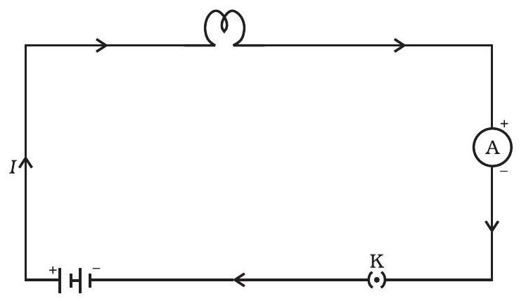
Figure 11.1 A schematic diagram of an electric circuit comprising - cell, electric bulb, ammeter and plug key
If a net charge
The SI unit of electric charge is coulomb (C), which is equivalent to the charge contained in nearly
Example 11.1
A current of
Solution
We are given,
From Eq. (11.1), we have
QUESTIONS
1. What does an electric circuit mean?
Show Answer
Answer
A continuous and closed path of an electric current is called an electric circuit. An electric circuit consists of electric devices, source of electricity and wires that are connected with the help of a switch.
2. Define the unit of current.
Show Answer
Answer
The unit of electric current is ampere (A).
3. Calculate the number of electrons constituting one coulomb of charge.
Show Answer
Answer
One electron possesses a charge of
Therefore,
11.2 ELECTRIC POTENTIAL AND POTENTIAL DIFFERENCE
What makes the electric charge to flow? Let us consider the analogy of flow of water. Charges do not flow in a copper wire by themselves, just as water in a perfectly horizontal tube does not flow. If one end of the tube is connected to a tank of water kept at a higher level, such that there is a pressure difference between the two ends of the tube, water flows out of the other end of the tube. For flow of charges in a conducting metallic wire, the gravity, of course, has no role to play; the electrons move only if there is a difference of electric pressure - called the potential difference along the conductor. This difference of potential may be produced by a battery, consisting of one or more electric cells. The chemical action within a cell generates the potential difference across the terminals of the cell, even when no current is drawn from it. When the cell is connected to a conducting circuit element, the potential difference sets the charges in motion in the conductor and produces an electric current. In order to maintain the current in a given electric circuit, the cell has to expend its chemical energy stored in it.
We define the electric potential difference between two points in an electric circuit carrying some current as the work done to move a unit charge from one point to the other -
Potential difference
The SI unit of electric potential difference is volt
The potential difference is measured by means of an instrument called the voltmeter. The voltmeter is always connected in parallel across the points between which the potential difference is to be measured.
Example 11.2
How much work is done in moving a charge of
Solution
The amount of charge
QUESTIONS
1. Name a device that helps to maintain a potential difference across a conductor.
Show Answer
Answer
Any source of electricity like battery, cell, power supply, etc. helps to maintain a potential difference across a conductor.
2. What is meant by saying that the potential difference between two points is
Show Answer
Answer
If
3. How much energy is given to each coulomb of charge passing through a
Show Answer
Answer
The energy given to each coulomb of charge is equal to the amount of work which is done in moving it.
Now we know that,
Potential difference
Where, Charge
11.3 CIRCUIT DIAGRAM
We know that an electric circuit, as shown in Fig. 11.1, comprises a cell (or a battery), a plug key, electrical component(s), and connecting wires. It is often convenient to draw a schematic diagram, in which different components of the circuit are represented by the symbols conveniently used. Conventional symbols used to represent some of the most commonly used electrical components are given in Table 11.1.
Table 11.1 Symbols of some commonly used components in circuit diagrams


11.4 OHM’S LAW
Is there a relationship between the potential difference across a conductor and the current through it? Let us explore with an Activity.
Activity 11.1
- Set up a circuit as shown in Fig. 11.2, consisting of a nichrome wire XY of length, say
, an ammeter, a voltmeter and four cells of each. (Nichrome is an alloy of nickel, chromium, manganese, and iron metals.) - First use only one cell as the source in the circuit. Note the reading in the ammeter
, for the current and reading of the voltmeter for the potential difference across the nichrome wire in the circuit. Tabulate them in the Table given.
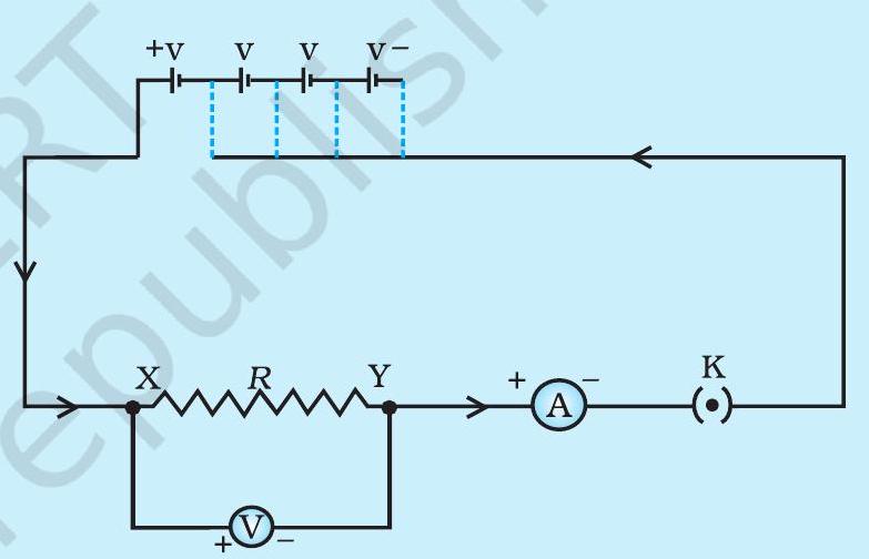
Figure 11.2 Electric circuit for studying Ohm’s law
- Next connect two cells in the circuit and note the respective readings of the ammeter and voltmeter for the values of current through the nichrome wire and potential difference across the nichrome wire.
- Repeat the above steps using three cells and then four cells in the circuit separately.
- Calculate the ratio of
| S. No. | Number of cells used in the circuit (ampere) | Current through the nichrome wire, |
Potential difference across the nichrome | |
|---|---|---|---|---|
| 1 | 1 | |||
| 2 | 2 | |||
| 3 | 3 | |||
| 4 | 4 |
- Plot a graph between
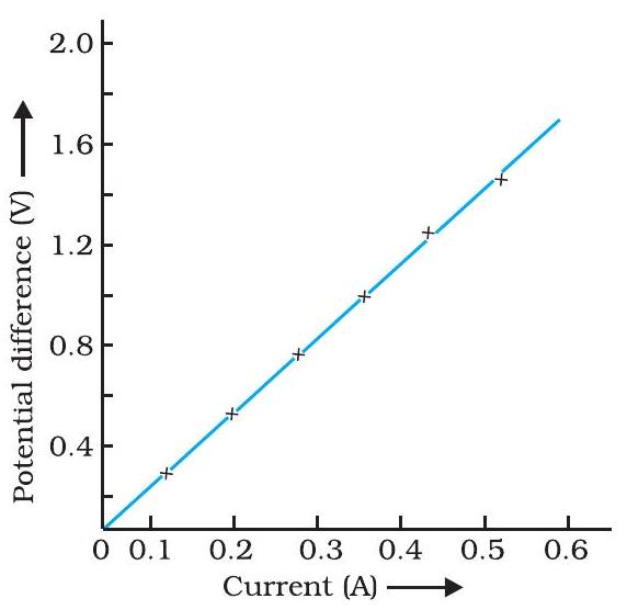
Figure 11.3
In this Activity, you will find that approximately the same value for
In 1827, a German physicist Georg Simon Ohm (1787-1854) found out the relationship between the current
or
or
In Eq. (11.4),
If the potential difference across the two ends of a conductor is
Also from Eq. (11.5) we get
It is obvious from Eq. (11.7) that the current through a resistor is inversely proportional to its resistance. If the resistance is doubled the current gets halved. In many practical cases it is necessary to increase or decrease the current in an electric circuit. A component used to regulate current without changing the voltage source is called variable resistance. In an electric circuit, a device called rheostat is often used to change the resistance in the circuit. We will now study about electrical resistance of a conductor with the help of following Activity.
Activity 11.2
- Take a nichrome wire, a torch bulb, a
bulb and an ammeter ( 0 - 5 A range), a plug key and some connecting wires. - Set up the circuit by connecting four dry cells of
each in series with the ammeter leaving a gap XY in the circuit, as shown in Fig. 11.4.

Figure 11.4
- Complete the circuit by connecting the nichrome wire in the gap XY. Plug the key. Note down the ammeter reading. Take out the key from the plug. [Note: Always take out the key from the plug after measuring the current through the circuit.]
- Replace the nichrome wire with the torch bulb in the circuit and find the current through it by measuring the reading of the ammeter.
- Now repeat the above step with the
- Are the ammeter readings different for different components connected in the gap XY? What do the above observations indicate?
- You may repeat this Activity by keeping any material component in the gap. Observe the ammeter readings in each case. Analyse the observations.
In this Activity we observe that the current is different for different components. Why do they differ? Certain components offer an easy path for the flow of electric current while the others resist the flow. We know that motion of electrons in an electric circuit constitutes an electric current. The electrons, however, are not completely free to move within a conductor. They are restrained by the attraction of the atoms among which they move. Thus, motion of electrons through a conductor is retarded by its resistance. A component of a given size that offers a low resistance is a good conductor. A conductor having some appreciable resistance is called a resistor. A component of identical size that offers a higher resistance is a poor conductor. An insulator of the same size offers even higher resistance.
11.5 FACTORS ON WHICH THE RESISTANCE OF A CONDUCTOR DEPENDS
Activity 11.3
- Complete an electric circuit consisting of a cell, an ammeter, a nichrome wire of length
[say, marked (1)] and a plug key, as shown in Fig. 11.5. 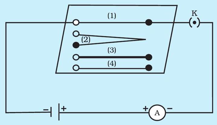
Figure 11.5 Electric circuit to study the factors on which the resistance of conducting wires depends
- Now, plug the key. Note the current in the ammeter.
- Replace the nichrome wire by another nichrome wire of same thickness but twice the length, that is
[marked (2) in the Fig. 11.5]. - Note the ammeter reading.
- Now replace the wire by a thicker nichrome wire, of the same length
[marked (3)]. A thicker wire has a larger cross-sectional area. Again note down the current through the circuit. - Instead of taking a nichrome wire, connect a copper wire [marked (4) in Fig. 11.5] in the circuit. Let the wire be of the same length and same area of cross-section as that of the first nichrome wire [marked (1)]. Note the value of the current.
- Notice the difference in the current in all cases.
- Does the current depend on the length of the conductor?
- Does the current depend on the area of cross-section of the wire used?
It is observed that the ammeter reading decreases to one-half when the length of the wire is doubled. The ammeter reading is increased when a thicker wire of the same material and of the same length is used in the circuit. A change in ammeter reading is observed when a wire of different material of the same length and the same area of cross-section is used. On applying Ohm’s law [Eqs. (11.5) - (11.7)], we observe that the resistance of the conductor depends (i) on its length, (ii) on its area of cross-section, and (iii) on the nature of its material. Precise measurements have shown that resistance of a uniform metallic conductor is directly proportional to its length
and
Combining Eqs. (11.8) and (11.9) we get
where
Table 11.2 reveals that the resistivity of an alloy is generally higher than that of its constituent metals. Alloys do not oxidise (burn) readily at high temperatures. For this reason, they are commonly used in electrical heating devices, like electric iron, toasters etc. Tungsten is used almost exclusively for filaments of electric bulbs, whereas copper and aluminium are generally used for electrical transmission lines.
Table 11.2 Electrical resistivity* of some substances at
| Material | Resistivity |
|
|---|---|---|
| Conductors | Silver | |
| Copper | ||
| Aluminium | ||
| Tungsten | ||
| Nickel | ||
| Iron | ||
| Chromium | ||
| Mercury | ||
| Manganese | ||
| Alloys | Constantan | |
| (alloy of Cu and Ni) | ||
| Manganin | ||
| (alloy of Cu, Mn and Ni) | ||
| Nichrome | ||
| (alloy of Ni, Cr, Mn and Fe) | ||
| Insulators | Glass | |
| Hard rubber | ||
| Ebonite | ||
| Diamond | ||
| Paper (Dry) |
- You need not memorise these values. You can use these values for solving numerical problems.
Example 11.3
(a) How much current will an electric bulb draw from a
Solution
(a) We are given
From Eq. (12.6), we have the current
(b) We are given,
From Eq. (11.6), we have the current
Note the difference of current drawn by an electric bulb and electric heater from the same
Example 11.4
The potential difference between the terminals of an electric heater is
Solution
We are given, potential difference
According to Ohm’s law,
When the potential difference is increased to
current
The current through the heater becomes
Example 11.5
Resistance of a metal wire of length
Solution
We are given the resistance
Therefore, from Eq. (11.10), the resistivity of the given metallic wire is
Substitution of values in this gives
The resistivity of the metal at
Example 11.6
A wire of given material having length
Solution
For first wire
Now for second wire
The resistance of the new wire is
QUESTIONS
1. On what factors does the resistance of a conductor depend?
Show Answer
Answer
The resistance of a conductor depends upon the following factors:
2. Will current flow more easily through a thick wire or a thin wire of the same material, when connected to the same source? Why?
Show Answer
Answer
The current will flow more easily through thick wire. It is because the resistance of a conductor is inversely proportional to its area of cross - section. If thicker the wire, less is resistance and hence more easily the current flows.
3. Let the resistance of an electrical component remains constant while the potential difference across the two ends of the component decreases to half of its former value. What change will occur in the current through it?
Show Answer
Answer
According to Ohm’s law
Now Potential difference is decreased to half
Resistance remains constant
So the new current
Therefore, the amount of current flowing through the electrical component is reduced by half.
4. Why are coils of electric toasters and electric irons made of an alloy rather than a pure metal?
Show Answer
Answer
The resistivity of an alloy is higher than the pure metal. Moreover, at high temperatures, the alloys do not melt readily. Hence, the coils of heating appliances such as electric toasters and electric irons are made of an alloy rather than a pure metal.
5. Use the data in Table 11.2 to answer the following –
(a) Which among iron and mercury is a better conductor?
(b) Which material is the best conductor?
Show Answer
Answer
Table 12.2 Electrical resistivity of some substances at
| - | Material | Resistivity |
|---|---|---|
| Conductors | Silver | |
| Copper | ||
| Aluminium | ||
| Tungsten | ||
| Nickel | ||
| Iron | ||
| Chromium | ||
| Mercury | ||
| Manganese | ||
| Constantan (alloy of Cu and Ni) |
||
| Alloys | Manganin (alloy of Cu, Mn and Ni) |
|
| :— | :— | :— |
| Nichrome (alloy of Ni, Cr, Mn and Fe) |
||
| Glass | ||
| Insulators | Hard rubber | |
| Ebonite | ||
| Diamond | ||
| Paper (dry) |
(a) Resistivity of iron
Resistivity of mercury
Resistivity of mercury is more than that of iron. This implies that iron is a better conductor than mercury.
(b) It can be observed from Table 12.2 that the resistivity of silver is the lowest among the listed materials. Hence, it is the best conductor.
11.6 RESISTANCE OF A SYSTEM OF RESISTORS
In preceding sections, we learnt about some simple electric circuits. We have noticed how the current through a conductor depends upon its resistance and the potential difference across its ends. In various electrical gadgets, we often use resistors in various combinations. We now therefore intend to see how Ohm’s law can be applied to combinations of resistors.
There are two methods of joining the resistors together. Figure 11.6 shows an electric circuit in which three resistors having resistances

Figure 11.6 Resistors in series
Figure 11.7 shows a combination of resistors in which three resistors are connected together between points
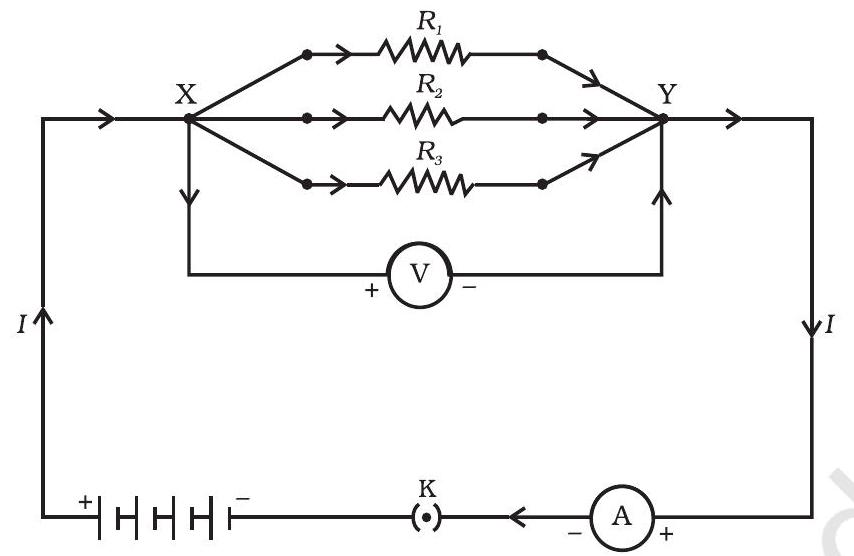
Figure 11.7 Resistors in parallel
11.6.1 Resistors in Series
What happens to the value of current when a number of resistors are connected in series in a circuit? What would be their equivalent resistance? Let us try to understand these with the help of the following activities.
Activity 11.4
- Join three resistors of different values in series. Connect them with a battery, an ammeter and a plug key, as shown in Fig. 11.6. You may use the resistors of values like
etc., and a battery of for performing this Activity. - Plug the key. Note the ammeter reading.
- Change the position of ammeter to anywhere in between the resistors. Note the ammeter reading each time.
- Do you find any change in the value of current through the ammeter?
You will observe that the value of the current in the ammeter is the same, independent of its position in the electric circuit. It means that in a series combination of resistors the current is the same in every part of the circuit or the same current through each resistor.
Activity 11.5
- In Activity 11.4, insert a voltmeter across the ends
and of the series combination of three resistors, as shown in Fig. 11.6. - Plug the key in the circuit and note the voltmeter reading. It gives the potential difference across the series combination of resistors. Let it be
. Now measure the potential difference across the two terminals of the battery. Compare the two values. - Take out the plug key and disconnect the voltmeter. Now insert the voltmeter across the ends
and of the first resistor, as shown in Fig. 11.8. - Plug the key and measure the potential difference across the first resistor. Let it be
. - Similarly, measure the potential difference across the other two resistors, separately. Let these values be
and , respectively. - Deduce a relationship between
and . 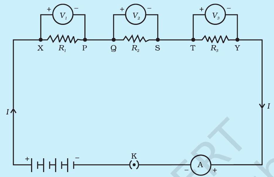
Figure 11.8
You will observe that the potential difference
In the electric circuit shown in Fig. 11.8 , let
On applying Ohm’s law to the three resistors separately, we further have
From Eq. (11.11),
or
We can conclude that when several resistors are joined in series, the resistance of the combination
Example 11.7
An electric lamp, whose resistance is
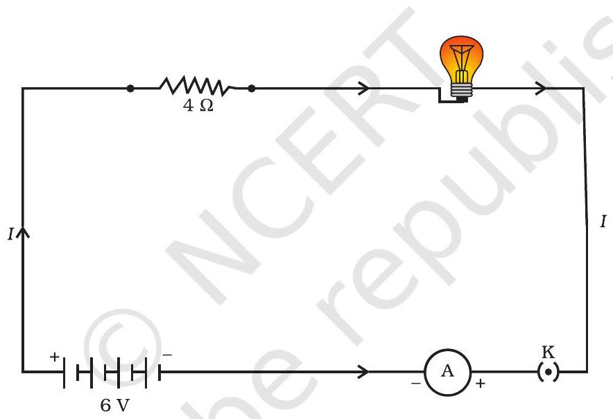
Figure 11.9 An electric lamp connected in series with a resistor of
Solution
The resistance of electric lamp,
The resistance of the conductor connected in series,
Then the total resistance in the circuit
The total potential difference across the two terminals of the battery
Now by Ohm’s law, the current through the circuit is given by
Applying Ohm’s law to the electric lamp and conductor separately, we get potential difference across the electric lamp,
and,
that across the conductor,
Suppose that we like to replace the series combination of electric lamp and conductor by a single and equivalent resistor. Its resistance must be such that a potential difference of
This is the total resistance of the series circuit; it is equal to the sum of the two resistances.
QUESTIONS
1. Draw a schematic diagram of a circuit consisting of a battery of three cells of
Show Answer
Answer
Three cells of potential

2. Redraw the circuit of Question 1, putting in an ammeter to measure the current through the resistors and a voltmeter to measure the potential difference across the
Show Answer
Answer
An ammeter should be connected in the circuit in series with the resistors. To measure the potential difference across the resistor it should be connected in parallel, as shown in the following figure.

The resistances are connected in series.
Ohm’s law can be used to obtain the readings of ammeter and voltmeter. According to Ohm’s law,
Where,
Potential difference,
Current flowing through the circuit/resistors
Resistance of the circuit,
Potential difference across
Current flowing through the
Therefore, using Ohm’s law, we obtain
Therefore, the reading of the ammeter will be
The reading of the voltmeter will be
11.6.2 Resistors in Parallel
Now, let us consider the arrangement of three resistors joined in parallel with a combination of cells (or a battery), as shown in Fig.11.7.
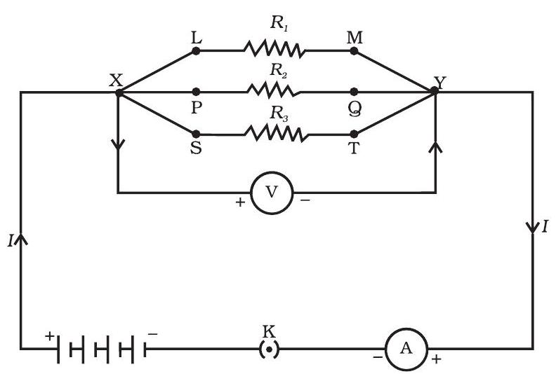
Figure 11.10
Activity 11.6
- Make a parallel combination, XY, of three resistors having resistances
, and , respectively. Connect it with a battery, a plug key and an ammeter, as shown in Fig. 11.10. Also connect a voltmeter in parallel with the combination of resistors. - Plug the key and note the ammeter reading. Let the current be
. Also take the voltmeter reading. It gives the potential difference , across the combination. The potential difference across each resistor is also . This can be checked by connecting the voltmeter across each individual resistor (see Fig. 11.11). - Take out the plug from the key. Remove the ammeter and voltmeter from the circuit. Insert the ammeter in series with the resistor
, as shown in Fig. 11.11. Note the ammeter reading, . 
Figure 11.11
- Similarly, measure the currents through
and . Let these be and , respectively. What is the relationship between and ?
It is observed that the total current
Let
On applying Ohm’s law to each resistor, we have
From Eqs. (11.15) to (11.17), we have
or
Thus, we may conclude that the reciprocal of the equivalent resistance of a group of resistances joined in parallel is equal to the sum of the reciprocals of the individual resistances.
Example 11.8
In the circuit diagram given in Fig. 11.10, suppose the resistors
Solution
Potential difference across the battery,
This is also the potential difference across each of the individual resistor; therefore, to calculate the current in the resistors, we use Ohm’s law.
The current
The current
The current
The total current in the circuit,
The total resistance
Thus,
Example 11.9
If in Fig. 11.12,
Solution
Suppose we replace the parallel resistors
Similarly,
that is,
Thus, the total resistance,
To calculate the current, we use Ohm’s law, and get
We have seen that in a series circuit the current is constant throughout the electric circuit. Thus it is obviously impracticable to connect an electric bulb and an electric heater in series, because they need currents of widely different values to operate properly (see Example 11 .3). Another major disadvantage of a series circuit is that when one component fails the circuit is broken and none of the components works. If you have used ‘fairy lights’ to decorate buildings on festivals, on marriage celebrations etc., you might have seen the electrician spending lot of time in trouble-locating and replacing the ‘dead’ bulb - each has to be tested to find which has fused or gone. On the other hand, a parallel circuit divides the current through the electrical gadgets. The total resistance in a parallel circuit is decreased as per Eq. (11.18). This is helpful particularly when each gadget has different resistance and requires different current to operate properly.
Figure 11.12 An electric circuit showing the combination of series and parallel resistors
QUESTIONS
1. Judge the equivalent resistance when the following are connected in parallel - (a)
Show Answer
Answer
(a) When
Let
Therefore, equivalent resistance
(b) When
Let
Therefore, equivalent resistance
2. An electric lamp of
Show Answer
Answer
Resistance of electric lamp,
Resistance of toaster,
Resistance of water filter,
Potential difference of the source,
These are connected in parallel, as shown in the following figure.
Let
According to Ohm’s law,
Where,
Current flowing through the circuit
7.04 A of current is drawn by all the three given appliances.
Therefore, current drawn by an electric iron connected to the same source of potential
Let
Therefore, the resistance of the electric iron is
3. What are the advantages of connecting electrical devices in parallel with the battery instead of connecting them in series?
Show Answer
Answer
There is no division of voltage among the appliances when connected in parallel. The potential difference across each appliance is equal to the supplied voltage.
The total effective resistance of the circuit can be reduced by connecting electrical appliances in parallel.
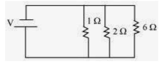
4. How can three resistors of resistances
Show Answer
Answer
There are three resistors of resistances
(a) The following circuit diagram shows the connection of the three resistors.
Here,
Therefore, their equivalent resistance will be given by
This equivalent resistor of resistance
Therefore, the equivalent resistance of the circuit
Hence the total resistance of the circuit is
(b) The following circuit diagram shows the connection of the three resistors.
All the resistors are connected in series. Therefore, their equivalent resistance will be given as
Therefore, the total resistance of the circuit is
5. What is (a) the highest, (b) the lowest total resistance that can be secured by combinations of four coils of resistance
Show Answer
Answer
There are four coils of resistances
(a) If these coils are connected in series, then the equivalent resistance will be the highest, given by the sum
(b) If these coils are connected in parallel, then the equivalent resistance will be the lowest, given by
Therefore,
11.7 HEATING EFFECT OF ELECTRIC CURRENT
We know that a battery or a cell is a source of electrical energy. The chemical reaction within the cell generates the potential difference between its two terminals that sets the electrons in motion to flow the current through a resistor or a system of resistors connected to the battery. We have also seen, in Section 11.2, that to maintain the current, the source has to keep expending its energy. Where does this energy go? A part of the source energy in maintaining the current may be consumed into useful work (like in rotating the blades of an electric fan). Rest of the source energy may be expended in heat to raise the temperature of gadget. We often observe this in our everyday life. For example, an electric fan becomes warm if used continuously for longer time etc. On the other hand, if the electric circuit is purely resistive, that is, a configuration of resistors only connected to a battery; the source energy continually gets dissipated entirely in the form of heat. This is known as the heating effect of electric current. This effect is utilised in devices such as electric heater, electric iron etc.
Consider a current
Or the energy supplied to the circuit by the source in time
Applying Ohm’s law [Eq. (11.5)], we get
This is known as Joule’s law of heating. The law implies that heat produced in a resistor is (i) directly proportional to the square of current for a given resistance, (ii) directly proportional to resistance for a given current, and (iii) directly proportional to the time for which the current flows through the resistor. In practical situations, when an electric appliance is connected to a known voltage source, Eq. (11.21) is used after calculating the current through it, using the relation
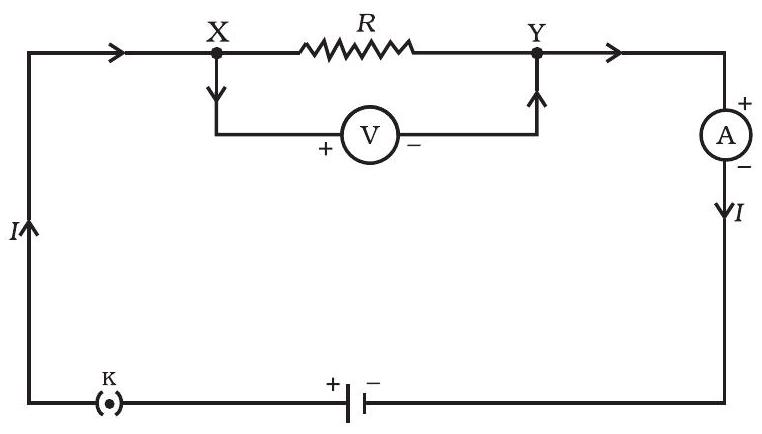
Figure 11.13 A steady current in a purely resistive electric circuit
Example 11.10
An electric iron consumes energy at a rate of
Solution
From Eq. (11.19), we know that the power input is
Thus the current
(a) When heating is at the maximum rate,
and the resistance of the electric iron is
(b) When heating is at the minimum rate,
and the resistance of the electric iron is
Example 11.11
Solution
From Eq. (11.21) we have the current through the resistor as
Thus the potential difference across the resistor,
QUESTIONS
1. Why does the cord of an electric heater not glow while the heating element does?
Show Answer
Answer
The heating element of the heater is made up of alloy which has very high resistance so when current flows through the heating element, it becomes too hot and glows red. But the resistance of cord which is usually of copper or aluminium is very law so it does not glow.
2. Compute the heat generated while transferring 96000 coulomb of charge in one hour through a potential difference of
Show Answer
Answer
Given Charge,
Time,
Potential difference,
Now we know that
So we have to calculate / first
As
Therefore, the heat generated is
3. An electric iron of resistance
Show Answer
Answer
The amount of heat
Time,
Voltage,
Therefore, the amount of heat developed in the electric iron is
11.7.1 Practical Applications of Heating Effect of Electric Current
The generation of heat in a conductor is an inevitable consequence of electric current. In many cases, it is undesirable as it converts useful electrical energy into heat. In electric circuits, the unavoidable heating can increase the temperature of the components and alter their properties. However, heating effect of electric current has many useful applications. The electric laundry iron, electric toaster, electric oven, electric kettle and electric heater are some of the familiar devices based on Joule’s heating.
The electric heating is also used to produce light, as in an electric bulb. Here, the filament must retain as much of the heat generated as is possible, so that it gets very hot and emits light. It must not melt at such high temperature. A strong metal with high melting point such as tungsten (melting point
Another common application of Joule’s heating is the fuse used in electric circuits. It protects circuits and appliances by stopping the flow of any unduly high electric current. The fuse is placed in series with the device. It consists of a piece of wire made of a metal or an alloy of appropriate melting point, for example aluminium, copper, iron, lead etc. If a current larger than the specified value flows through the circuit, the temperature of the fuse wire increases. This melts the fuse wire and breaks the circuit. The fuse wire is usually encased in a cartridge of porcelain or similar material with metal ends. The fuses used for domestic purposes are rated as
11.8 ELECTRIC POWER
You have studied in your earlier Class that the rate of doing work is power. This is also the rate of consumption of energy.
Equation (11.21) gives the rate at which electric energy is dissipated or consumed in an electric circuit. This is also termed as electric power. The power
The SI unit of electric power is watt (W). It is the power consumed by a device that carries
The unit ‘watt’ is very small. Therefore, in actual practice we use a much larger unit called ‘kilowatt’. It is equal to 1000 watts. Since electrical energy is the product of power and time, the unit of electric energy is, therefore, watt hour (W h). One watt hour is the energy consumed when 1 watt of power is used for 1 hour. The commercial unit of electric energy is kilowatt hour (kW h), commonly known as ‘unit’.
More to know!
Many people think that electron are consumed in a electric circuit. This is wrong! We pay the electricity board or electric company to provide energy to move electrons through the electric gadgets like electric bulb, fan and engines. We pay fir the energy that we use.
Example 11.12
An electric bulb is connected to a
Solution
Example 11.13
An electric refrigerator rated
Solution
The total energy consumed by the refrigerator in 30 days would be
Thus the cost of energy to operate the refrigerator for 30 days is
QUESTIONS
1. What determines the rate at which energy is delivered by a current?
Show Answer
Answer
The rate of consumption of electric energy in an electric appliance is called electric power. Hence, the rate at which energy is delivered by a current is the power of the appliance.
2. An electric motor takes 5 A from a 220 V line. Determine the power of the motor and the energy consumed in
Show Answer
Answer
Power
Where,
Voltage,
Current,
Energy consumed by the motor
Where,
Time,
Therefore, power of the motor
Energy consumed by the motor
What you have learnt
- A stream of electrons moving through a conductor constitutes an electric current. Conventionally, the direction of current is taken opposite to the direction of flow of electrons.
- The SI unit of electric current is ampere.
- To set the electrons in motion in an electric circuit, we use a cell or a battery. A cell generates a potential difference across its terminals. It is measured in volts (V).
- Resistance is a property that resists the flow of electrons in a conductor. It controls the magnitude of the current. The SI unit of resistance is ohm
- Ohm’s law: The potential difference across the ends of a resistor is directly proportional to the current through it, provided its temperature remains the same.
- The resistance of a conductor depends directly on its length, inversely on its area of cross-section, and also on the material of the conductor.
- The equivalent resistance of several resistors in series is equal to the sum of their individual resistances.
- A set of resistors connected in parallel has an equivalent resistance
- The electrical energy dissipated in a resistor is given by
- The unit of power is watt (W). One watt of power is consumed when
- The commercial unit of electrical energy is kilowatt hour (kWh).
EXERCISES
1. A piece of wire of resistance
(a)
(b)
(c)
(d)
Show Answer
Answer
(d) 25
2. Which of the following terms does not represent electrical power in a circuit?
(a)
(b)
(c)
(d)
Show Answer
Answer
(b)
3. An electric bulb is rated
(a)
(b)
(c)
(d)
Show Answer
Answer
(d)
4. Two conducting wires of the same material and of equal lengths and equal diameters are first connected in series and then parallel in a circuit across the same potential difference. The ratio of heat produced in series and parallel combinations would be -
(a)
(b)
(c)
(d)
Show Answer
Answer
(c)
5. How is a voltmeter connected in the circuit to measure the potential difference between two points?
Show Answer
Answer
To measure the potential difference between two points, a voltmeter should be connected in parallel to the points.
6. A copper wire has diameter
Show Answer
Answer
Area of cross-section of the wire,
Diameter
Resistance,
We know that
If the diameter of the wire is doubled, new diameter
Therefore, the length of the wire is
7. The values of current
| 0.5 | 1.0 | 2.0 | 3.0 | 4.0 | |
| 1.6 | 3.4 | 6.7 | 10.2 | 13.2 |
Plot a graph between
Show Answer
Answer
The plot between voltage and current is called
| 1.6 | 3.4 | 6.7 | 10.2 | 13.2 | |
|---|---|---|---|---|---|
| 0.5 | 1.0 | 2.0 | 3.0 | 4.0 |
The IV characteristic of the given resistor is plotted in the following figure.

The slope of the line gives the value of resistance
Slope
Therefore, the resistance of the resistor is
8. When a
Show Answer
Answer
Resistance
Where,
Potential difference,
Current in the circuit,
Therefore, the resistance of the resistor is
9. A battery of
Show Answer
Answer
There is no current division occurring in a series circuit. Current flow through the component is the same, given by Ohm’s law as
Where,
Potential difference,
Therefore, the current that would flow through the
10. How many
Show Answer
Answer
For
Where,
Supply voltage,
Current,
Equivalent resistance of the combination
From Ohm’s law,
Therefore, four resistors of
11. Show how you would connect three resistors, each of resistance
Show Answer
Answer
If we connect the resistors in series, then the equivalent resistance will be the sum of the resistors, i.e.,
(a) Two resistor in parallel

Two
The third
(b) Two resistor in series

Two
Therefore, the total resistance is
12. Several electric bulbs designed to be used on a
Show Answer
Answer
Resistance
Supply voltage,
Maximum allowable current,
Rating of an electric bulb
Because
According to Ohm’s law,
Let
Resistance of each electric bulb,
13. A hot plate of an electric oven connected to a
Show Answer
Answer
Supply voltage,
Resistance of one coil,
(i) Coils are used separately
According to Ohm’s law,
Where,
Therefore, 9.16 A current will flow through the coil when used separately.
(ii) Coils are connected in series
Total resistance,
According to Ohm’s law,
Where,
Therefore,
(iii) Coils are connected in parallel
Total resistance,
According to Ohm’s law,
Where,
Therefore, 18.33 A current will flow through the circuit when coils are connected in parallel.
14. Compare the power used in the
Show Answer
Answer
(i) Potential difference,
According to Ohm’s law,
Where,
This current will flow through each component of the circuit because there is no division of current in series circuits. Hence, current flowing through the
(ii) Potential difference,
Power consumed by
Therefore, the power used by
15. Two lamps, one rated
Show Answer
Answer
Both the bulbs are connected in parallel. Therefore, potential difference across each of them will be
Current drawn by the bulb of rating
Current
Hence, current drawn from the line
16. Which uses more energy, a
Show Answer
Answer
Energy consumed by an electrical appliance is given by the expression,
Where,
Power of the appliance
Time
Energy consumed by a TV set of power
Energy consumed by a toaster of power
Energy consumed by a toaster of power
Therefore, the energy consumed by a
17. An electric heater of resistance
Show Answer
Answer
Rate of heat produced by a device is given by the expression for power as,
Current drawn,
Therefore, heat is produced by the heater at the rate of
18. Explain the following.
(a) Why is the tungsten used almost exclusively for filament of electric lamps?
(b) Why are the conductors of electric heating devices, such as bread-toasters and electric irons, made of an alloy rather than a pure metal?
(c) Why is the series arrangement not used for domestic circuits?
(d) How does the resistance of a wire vary with its area of cross-section?
(e) Why are copper and aluminium wires usually employed for electricity transmission?
Show Answer
Answer
(a) The melting point and of Tungsten is an alloy which has very high melting point and very high resistivity so does not burn easily at a high temperature.
(b) The conductors of electric heating devices such as bread toasters and electric irons are made of alloy because resistivity of an alloy is more than that of metals which produces large amount of heat.
(c) In series circuits voltage is divided. Each component of a series circuit receives a small voltage so the amount of current decreases and the device becomes hot and does not work properly. Hence, series arrangement is not used in domestic circuits.
(d) Resistance (R) of a wire is inversely proportional to its area of cross-section (A), i.e. when area of cross section increases the resistance decreases or vice versa.
(e) Copper and aluminium are good conductors of electricity also they have low resistivity. So they are usually used for electricity transmission.


