Chapter 07 Electromagnetism Induction And Alternating Current
Introduction
We use generator or dynamo to produce electricity when the power supply disappears. They have a coil, called the armature, rotating in a magnetic field and convert the mechanical energy, i.e., the rotational kinetic energy, into the electrical energy. These electromechanical devices are based on the principle of what is called the electromagnetic induction. It is the phenomenon is which a changing magnetic field produces an induced emf and current. This chapter is all about this phenomenon and the alternating current.
The alternating currents play an important role in the present day technology and industry. The transmission of electrical power over the long distances becomes very much easier and more economical with the alternating currents than the direct currents. The circuits used in the modern communication systems, including the radio and television, computer systems, and so on, make an extensive use of the alternating currents. The alternating currents are involved in the many life processes. The electrocardiography, i.e., the detection and study of alternating currents induced in the surrounding tissues due to the heart beating, provides a valuable information about the health and pathology of heart. The electroencepnalograms, being the recordings of alternating currents in the brain, provide a vital information regarding the functioning of brain.
ELECTROMAGNETIC INDUCTION
In the early 1800 s, the only current-producing devices were voltaic cells, which produced small currents by dissolving metals in acids. These were the forerunners of our present-day batteries. The question arose as to whether electricity could be produced from magnetism. The answer was provided in 1831 by two physicists, Michael Faraday in England and Joseph Henry in the United Stateseach working without knowledge of the other. Their discovery changed the world by making electricity commonplace-powering industries by day and lighting up cities at night.
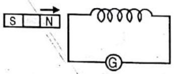
Faraday and Henry both discovered that electric current could be produced in a wire simply by moving a magnet into or out of a coil of wire. (Figure 7.1). No battery or other voltage source was needed-only the motion of a magnet in a wire loop. They discovered that voltage is caused, or induced, by the relative motion between a wire and a magnetic field. Whether the magnetic field moves near a stationary conductor or vice versa, voltage is induced either way (Figure 7.2).
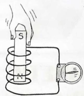
Fig. 7.1, When the magnet is plunged into the coil, charges in the coil are set in motion, and voltage is induced in the coil.
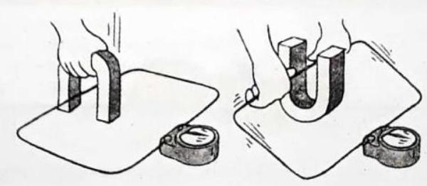
Fig. 7.2. Voltage is induced in the wire loop whether the magnetic field moves past the wire or the wire moves through the magnetic field.
The greater the number of loops of wire moving in a magnetic field, the greater the induced voltage (Figure 7.3). Pushing a magnet into a coil with twice as many loops induces twice as much voltage; Pushing into a coil with ten times as many loops induces ten times as much voltage; and so on. It may seem that we get something (energy) for nothing simply by increasing the number of loops in a coil of wire, but we don’t: We find that it is more difficult to push the magnet into a coil made up of more loops. This is because the induced voltage produces a current, which makes an electromagnet, which repels the magnet in our hand. So we must do more work against this “back force” to induce more voltage (Figure 7.4).
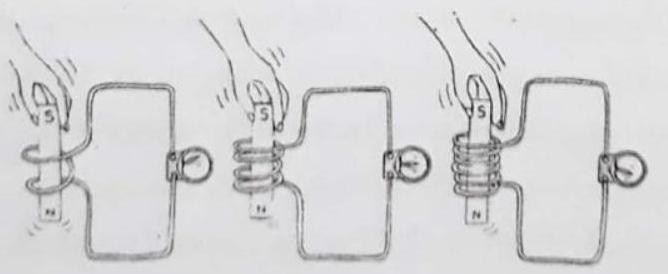
Fig. 7.3, When a magnet is plunged into a coil with iwice as many loops as another, nvice as much voltage is induced. If the magnet is plunged into a coil with three times as many loops, three times as much voltage is induced.
Fig. 7.4. It is more difficult to push the magnet into a coil with many loops because the magnetic field of each current loop resists the motion of the magnet.
The amount of voltage induced depends on how fast the magnetic field lines are entering or leaving the coil. Very slow motion produces hardly any voltage at all. Rapid motion induces a greater voltage. This phenomenon of inducing voltage by changing the magnetic field in a coil of wire is called electromagnetic induction.
FARADAY’S EXPERIMENT
In 1831, Michael Faraday carried out numerous experiments in his attempt to prove that electricity could be generated from magnetism. Within the course of a few weeks, the great experimentalist not only had clearly demonstrated this phenomenon, now known as electromagnetic induction, but also had developed a good conception of the processes involved.
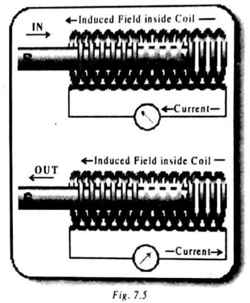
When a bar magnet is thrust into a coil connected to an electric circuit, a current is caused to flow in the circuit to which the coil is attached. If the magnet is withdrawn, the direction of the current is reversed. Such currents are called induced currents.
The size of the current depends on how fast the magnet moves in or out of the coil, and the number of loops in the coil.
The phenomenon of inducing a current by changing the magnetic field in a coil of wire is known as electromagnetic induction. This phenomenon underpins the design of all electric generators.
FARADAY’S EXPERIMENTS AND OBSERVATION :
| Experiment | Observation | |||
|---|---|---|---|---|
| 1. | Place a magnet near a conducting loop with a galvanometer in the circuit | No current flows through the galvanometer. | ||
| 2. | Move the magnet towards the loop. | The galvanometer register a current. | ||
| 3. | Reverse the direction of motion of the magnet | The gavanometer deflection reverses | ||
| 4. | Reverse the polarity of the magnet and move the magnet towards the loop | The deflection reverses | ||
| 5. | Keep magnet fixed and move the coil towards the magnet | The galvanometer register a current. | ||
| 6. | Increases the speed of the magnet | The deflection increases | ||
| 7. | Increase the strength of the magnet | The deflection increases | ||
| 8. | Increase the diameter of the coil | The deflection increases | ||
| 9. | Fix the speed of the magnet but repeat the experiment with the magnet closer to the coil. | The deflection increases | ||
| 10. | Move the magnet at an angle to the plane of the coil. | Deflection decreases Deflection is maximum when the magnet moves perpendicular to the plane of the coil. Deflection is zero when the magnet moves parallel to the plane of the coil. |
||
| 11. | Increase the number of turns of the coil | Magnitude of current increases |
COIL-COIL EXPERIMENTS
A coil known as primary
The following observations are made
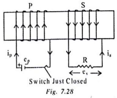
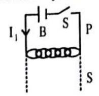
(i) When the key is pressed, the galvanometer shows a momentary deflection.
(ii) When the current becomes steady i.e. key is kept pressed, the deflection is zero.
(iii) When the key is released, the galvanometer again shows a momentary deflection, but now in the opposite direction.
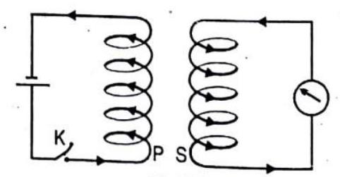
Fig. 7.11
These observations reveal that as long as there is a change in current in P, an e.m.f. is induced in S. This phenomenon in which an e.m.f. is induced in a coil due to a varying current in a neighbouring coil is called mutual induction.
It can also be seen that on keeping
These observations show that an e.m.f is induced in the coil, whenever there is a relative motion between the magnet and the coil.
MAGNETIC FLUX
To represent magnetic lines of forces quantitatively magnetic flux is used.
If the magnetic field
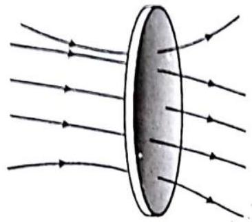
Fig. 7.12 The magnetic flux for a surface is proportional to the number of filed lines intersecting the surface.
So, magnetic flux linked with a closed surface may be defined as the product of the surface area and the normal component of the magnetic field acting on that area. It may also defined as the dot or scalar product of magnetic field and surface area. Physically it represents total lines of induction passing through a given area.
Positive and negative flux
In case of a body present in a field, either uniform or non-uniform, outward flux is taken to be positive while inward negative,
If the normal drawn on the surface is in the direction of the field, then the flux is taken as positive. In this case,
If the normal on the surface is opposite to the direction of the field, then
In this case, the magnetic flux is taken as negative.
Magnetic flux density,
302 Electromagnetic Induction and Alternating Current | Physics |
Different ways which can vary the magnetic flux
Magnetic flux in planar area
Fig. 7.15 Flux changes as B changes
So flux linked with a circuit will change only if field
(1) By varying the magnetic field
Due to motion of magnet B will change with time.
Or if magnetic field produced due to current carrying loop then due to change in current change in B will occur with time.
(2) By varying the area of the conducting loop
The second method of inducing a change in flux is to vary the area of the conducting loop with time.
(a) Change in Shape of the loop
Consider a square loop of side “a” placed perpendicular to a uniform and steady magnetic field B. Suppose the square loop transforms into a circular loop of the same circumference.
Initial area of the loop
The initial flux through the loop
The final radius of the circular loop
The final flux through the loop
The net change in flux

(b) Rod Translating in a
A conducting rod is placed on this wire so as to short the two arms of the
Let the distance between the two arms of the
Now suppose the rod translates to the right with a speed

(3) Loop entering or leaving a finite region of magnetic field
(a) Rectangular loop passing through magnetic field
Method for creating a loop with a time varying area is to have a closed loop enter or leave a region of magnetic field. Here the actual area of the loop does not change with time. However, the effective area of the loop through which magnetic field lines pass, varies with time.

(b) Loop rotating in and out of a finite region of magnetic field :
Consider a semicircular loop placed at the edse
field. The loop rotates with an angular velocity

Fig. 7.19
(4) Effect of time varying angle between the area vector and the magnetic field vector
Consider a circular loop placed in an uniform magnetic field
The flux linked with a loop
If
FARADAY’S LAWS OF ELECTRO-MAGNETIC INDUCTION
Whenever there is change in the magnetic flux associated with a circuit, an e.m.f. is induced in the circuit.
The magnitude of the induced e.m.f. (e) is directly proportional to the time rate of change of the magnetic flux through the circuit.
In the S.I. system, e.m.f. ’e’ is measured in volt and
In MKS or SI system, these units are so chosen that
Faraday’s laws do not give the direction of the induced e.m.f. or current.
Induced current or e.m.f. lasts only for the time for which the magnetic flux is changing. If the coil has
So, the induced e.m.f in the whole coil
FLEMING’S RIGHT HAND RULE
Fleming’s right hand rule gives the direction of the induced e.m.f. and current in a straight conductor moving perpendicular to the direction of magnetic field.
Statement : Stretch out the thumb, fore finger and middle finger of the right hand mutually perpendicular to each other. If the fore finger points in the direction of magnetic field, the thumb in the direction of motion of the conductor, then the middle finger will point out the direction of induced current or induced e.m.f.
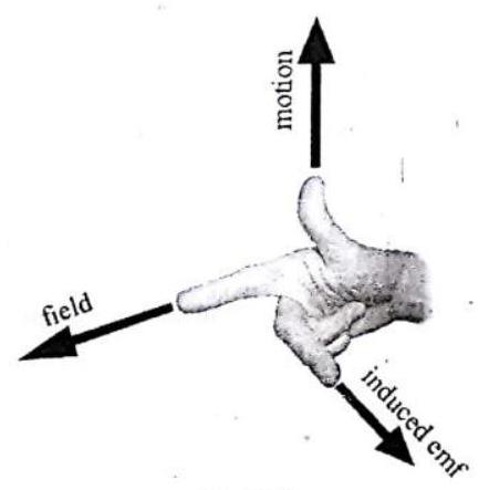
Fig. 7.22
LENZ’S LAW
The direction of the induced current is given by Lenz’s law
The direction of the induced current is such that it oppose the change in the magnetic flux that causes the induced current or e.m.f. i.e. induced current tries to maintain flux.
On combining Lenz’s law with Faraday’s laws
-ve sign indicating that the induced e.m.f. opposes the change in the magnetic flux.
The Lenz’s Law is consistent with the law of conservation of energy.
The induced e.m.f. is produced at the cost of mechanical work done by an external agent in the magnet and coil experiment. When the
As the magnet is moved towards the coil, the magnetic flux linked with the coil increases.
To oppose this increase in flux, e.m.f. induced in the coil has to be in such a direction as to reduce the increase in flux. The external agent has to do some work against this force of repulsion between the two
The external agent has to do work against this force of attraction between the
If suppose, on moving the
Check Point
If your metal car moves over a wide, closed loop of wire embedded in a road surface, will the magnetic field of the earth within the loop be altered? Will this produce a current pulse? Can you think of a practical application for this at a traffic intersection?
Show Answer
SOLUTION:
Yes, our metal cars moving over a wide, closed loop of wire embedded in a road surface, change the magnetic field of the earth within the loop.
This change in the magnetic field induces currents in the wire loops and a current pulse is produced. At a traffic intersection, the colour of the traffic light changes as a result of these current pulses.
Knowledge ENHANCER
Determination of the direction of the induced current in a circuit (Using Lenz’s Law)
Lenz’s law: “when the magnetic flux through a loop changes, a current is induced in the loop such that the magnetic field due to the induced current opposes the change in the magnetic flux through the loop”.
The above rule can be systematically applied as follows to determine the direction of induced currents.
(A) Identify the loop in which the induced current is to be determined
(b) Determine the direction of the magnetic field in this loop (i.e., in or out of the loop)
(c) The direction of flux is the same as the direction of the magnetic field
Determine if the flux through the loop is increasing or decreasing
(due to change in area, or change in B).
(d) Choose the appropriate current in the loop that will oppose the change in flux i.e.,
a. If the flux is into the paper and increasing, the flux due to the induced current should be out of the paper.
b. If the flux into the paper and decreasing, the flux due to the induced current should be into the paper.
c. If the flux is out of the paper and increasing, the flux due to the induced current should be into the paper.
d. If the flux is out of the paper and decreasing, the flux due to induced current should be out of the paper.
The above description is the physical interpretation of Lenz’s law.
SIGN CONVENTION FOR INDUCED EMF
Positive Induced EMF
When the magnetic flux
Fig. 7.24
NEGATIVE INDUCED EMF
When the magnetic flux
Fig. 7.25
ILLUSTRATION-7.1
A cir cular wire loop of radius
Show Answer
SOLUTION:
The given circular loop of radius
When this loop is deformed into the square loop, it’s linear size will be
The decrease in the area of loop is
and the decrease in the magnetic flux through the loop becomes
Finally, the average e.m.f. induced in the loop is of magnitude
SELF INDUCTION
The property of a coil by virtue of which the coil opposes any change in the strength of the current flowing through it, by inducing an e.m.f. in itself is called self inductance.
When a current I flows through a coil, the magnetic flux
direction in which
If
Where
ILLUSTRATION-7.2
A conducting rectangular loop of breadth,
Fig. 7.27
Show Answer
SOLUTION:
When the rectangular loop is pushed downwards with the velocity
and the current induced in the loop will be
which flows in the clockwise direction so as to counterbalance the decrease in magnetic flux, according to the Lenz’s law.
The net magnetic force on the loop, acting vertically upwards on the upper side, according to the ‘Fleming’s Left-Hand Rule’,
is
which balances the weight
Keep in memory
1. Energy stared in a cail
2. She self inductance is a measure of the coil to oppose the flow of current through it. The role of self-inductance in an electrical circuit is the same as that of the inertia in mechanics. Therefore it is called electrical inertia.
3. The magnetic energy density (energy stored per unit volume) in a salenoid
MUTUAL INDUCTION
The mutual induction is another kind of electromagnetic induction in which a changing current
When a constant, or variable, current
where the constant of proportionatity
If the primary current
which means that the mutual inductance
UNIT OF INDUCTANCE : Henry(H)
COMBINATIONS OF INDUCTANCES
Series Combination
Let us consider a series combination of two inductors of inductances
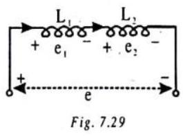
Then, the total potential difference across the two inductors in series, taken together, is
where
Parallel Combination
Let us now consider the two inductors of inductances
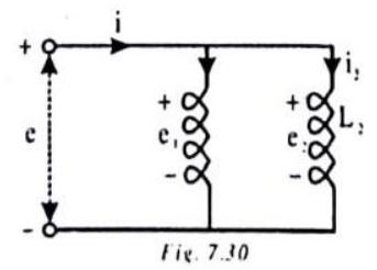
The total potential difference across the two inductors in parallel, taken together, is equal to the potential difference across each one of them, taken separately.
However, the current divides into
ELECTRIC GENERATOR
The large generators present in hydroelectric power plants depend on magnets for their operation. They convert the kinetic anergy in moving water into electricity. Generators in fossil-fueled and nuclear-fueled power plants harness the kinetic energy in moving steam in the same way.
Electrical current can be generated by moving a metal wire through a magnetic field. This applies both to alternating current (AC) and direct current (DC) electricity.
When a coil of conducting wire is rotated in a magnetic field, electromagnetic induction results in an induced current flowing through the loop. In this way, mechanical energy is converted to electrical energy. The device is called a generator or dynamo. The generator will produce an electromotive force that will vary sinusoidally with the angle made by the coil and the applied field. Thus the direction of the current will vary and the current so produced is called an alternating current. A better name for the device is alternator.
Note that this is analogous to an electric motor: the motor converts electrical energy into mechanical energy, while the alternator converts mechanical energy into electrical energy. The alternator does not create electricity out of nothing.
Working of generator : An electric generator, consists of a rotating rectangular coil
Outer ends of the two brushes are connected to the galvanometer to show the flow of current in the given external circuit. When the axle attached to the two rings is rotated such that the arm
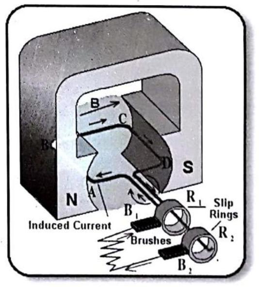
Fig.
After half a rotation, arm CD starts moving up and
The current in the external circuit now flows from
Fig. 7.32 : Split-ring type commutator.
To get a direct current (DC, which does not change its direction with time), a split-ring type commutator must be used. With this arrangement, one brush is at all times in contact with the arm moving up in the field, while the other is in contact with the arm moving down.
The difference between the direct and alternating currents is that the direct current always flows in one direction, whereas the alternating current reverses its direction periodically. Most power stations constructed these days produce AC. In India, the AC changes direction after every 1/100 second, that is, the frequency of AC is
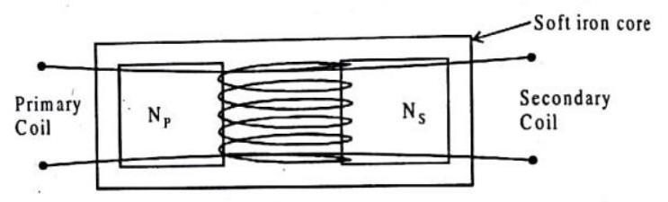
TRANSFORMER
When changes in the magnetic field of a current-carrying coil of wire are intercepted by a second coil of wire, voltage is induced in the second coil. This is the principle of the transformer-a simple electromagneic-induction device consisting of an input coil of wire (the primary) and an output coil of wire (the secondary). The coils need not physically touch each other, but they are normally wound on a comman iron core so that the magnetic field of the primary passes through the secondary. The primary is powered by an AC voltage source, and the secondary is connected to some external circuit. Changes in the primary current produce changes in its magnetic field. These changes extend to the secondary, and by electromagnetic induction, voltage is induced in the secondary. If the number of turns of wire in both coils is the same, voltage input and voltage output will be the same. Nothing is gained. But, if the secondary has more turns than the primary, then greater voltage will be induced in the secondary. This is a step-up transformer. If the secondary has fewer turns than the primary, the AC voltage induced in the secondary will be lower than that in the primary. This is a step-down transformer.
Fig. 7.34 : A practical transformer. The iron coil guides the changing magnetic field lines.
The relationship between primary und secondary voltages relative to the number of turns is
It might seem that we get something for nothing with a trunsformer that steps up the voltage, but we don’t, When voltage is stepped up, current in the secondary is less than in the primary. The transformer actually transfers energy from one coil to the other. The rate of transferring energy is power. The power used in the secondary is supplied by the primary. The primary gives no more than the secondary uses, in aceord with the law of energy conservation, If the slight power losses due to heating of the core are neglected, then
Power into primary
Electric power is equal to the product of voltage and eurrent, so we can say that
The ease with which voltages can be stepped up or down with a transformer is the principle reason that most electric power is AC rather than DC.
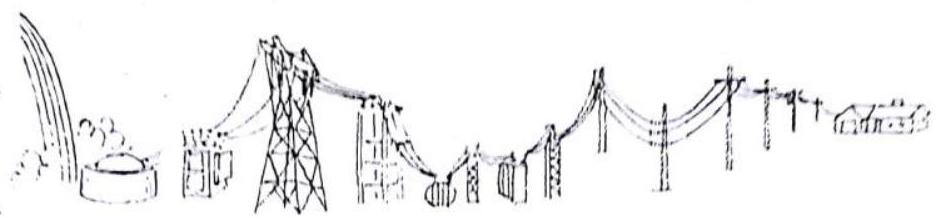
Fig. 7.35 Voltage generated in power stations is stepped nip, with transformers prior to being transferred across country by overhead cables. Then other transformers reduce the voltage before supplying it to homes, offices, and factories.
ENERGY LOSSES IN GENERATORS AND MOTORS
Copper loss, or Joule-Heating Loss
This loss arises due to the ‘Joule Heating’ of coils, carrying the electric currents.
Iron loss, or Eddy-Current loss
This loss is associated with the eddy currents, i.e., currents of circulating nature, induced in the iron cores and can be minimised by doing the lamination of cores.
Hysteresis loss
This loss is associated with the magnetisation of ferromagnetic cores and can be minimised by using the ferromagnetics, having the thin hysteresis loops, e.g., solt iron.
Magnetic Flux leakage
The magnetic flux leakage from the current-carrying coils amounts to the loss of energy.
Mechanical loss
This loss is due to the friction at the bearings of moving parts, air resistance, etc.
Check Point
Two separate but similar coils of wire are moutned close to each other, as shown below. The first coil is connected to a battery and has a direct current flowing through it. The second coil is connected to a galvanometer. How does the galvanometer respond when the switch int he first circuit is closed? After being closed when the switch is opened?
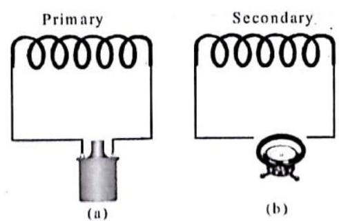
Fig. 7.36
Show Answer
SOLUTION:
When the switch in the first circuit is closed, the current in the coil grows from zero to a maximum value. Correspondingly, a magnetic field is generated by the current in the second coil, which increases with the current. This increasing magnetic field induces a voltage in the second coil and a current flows in this coil. Thus, the galvanometer deflects in one direction from zero to a maximum value.
When the switch in the first coil is closed, the current increases from zero and reaches to a maximum steady value after a long time which depends on the resistance of the conducting wire and the inductance of the coil.
The switch can be opened after the current reaches a steady value. In this case, the current will tend to zero from the steady maximum value and the galvanometer will show deflection in the opposite direction.
ILLUSTRATION-7.3
A lossless transformer steps down
Show Answer
SOLUTION:
In the lossless transformer, we are given that
and hence,
ILLUSTRATION-7.4
In a transformer, the primary and secondary have 1000 and 3000 turns, respectively. If the primary is connected across an ac source of
Show Answer
SOLUTION:
In the transformer, we have
and then, the voltage across each turn of secondary becomes
ILLUSTRATION-7.5
A transformer is used to step-down a voltage from
Show Answer
SOLUTION:
The efficiency of transformer is
EDDY CURRENTS (FOUCAULT CURRENTS)
The induced circulating currents produced in a metal itself due to change in magnetic flux linked with the metal are called eddy currents.
These currents were discovered by Foucault, so they are also known as Foucault Currents.
The direction of eddy currents is given by Lenz’s law.
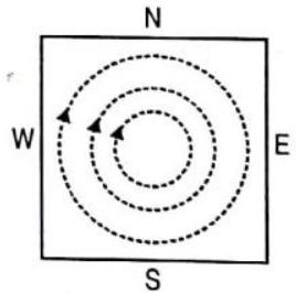
Eddy currents produced in a metallic block moving in a non-uniform magnetic field are shown in fig. 7.37.
Fig. 7.37
KNOWLEDGE ENHANCER
Demonstration of Eddy Currents
Jumping Disc :
An aluminium disc is placed over the core of an electro-magnet.
When the circuit is closed i.e., altemating current flows in the circuit, the disc jumps up to a certain height.
When the current through the solenoid increases, the magnetic flux along the axis of the solenoid increases. Consequently, the magnetic flux linked with the disc also increases. Due to the change in magnetic flux, induced currents (i.e. eddy currents) are produced in the disc and it is slightly magnetised. If the upper face of the core of the electromagnet acquires north polarity, then according to Lenz’s law, the lower face of the disc will also acquire North polarity. Due to the force of repulsion between the lower face (
Fig. 7.38
ALTERNATING CURRENT (A.C.)
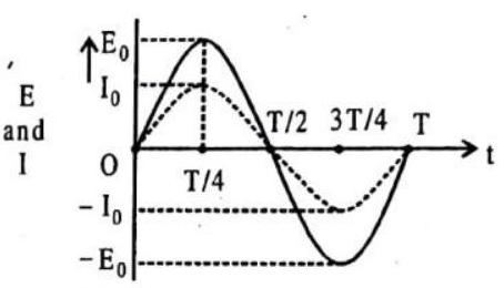
An alternating current is one which periodically changes in magnitude and direction. It increases from zero to a maximum value, then decreases to zero and reverses in direction, increases to a maximum in this direction and then decreases to zero.
The alternating currents change both in magnitude and direction periodically. They have the various different waveforms, or waveshapes, e.g., sinusoidal, square, triangualr, sawtoothed, and so on, depending on their applications. The alternating currents, in the normal use, have the sinusoidal waveform and represented analytically as
where
The alternating currents are generated in the circuits energised by the sources of alternating e.m.f., or voltage, such as, the ac generators and electronic oscillators, represented graphically by the symbol
The sinusoidal e.m.f.s, or voltages, are represented analytically as
where
ADVANTAGES OF A.C. OVER D.C
(i) The generation of A.C. is cheaper than that of D.C.
(ii) Alternating voltage can be easily stepped up or stepped down by using a transformer.
(iii) A.C. can be easily converted into D.C. by rectifier.
(iv) It can be transmitted to a long distance without appreciable loss.
AVERAGE OR MEAN, VALUE OF ALTERNATING CURRENT
The average or mean, value of sinusoidal current
It is zero because the integral represents the area between the curve and time axis over a complete cycle and this area is negative as much as it positive. This is the reason that if a sinusoidal current is sent through a moving-coil galvanometer, it reads zero. The non-zero average, or mean, value of sinusoidal current
This average value is the height of rectangle, shown shaded in the figure, having it’s area equal to the area under one loop of the sine curve.
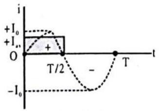
Fig. 7.41
Similarly, the non-zero average, or mean, value of sinusoidal e.m.f., or voltage,
ROOT-MEAN SQUARE (RMS) VALUE OF ALTERNATING CURRENT
Most of the ac meters are calibrated to record not the peak value of alternating current, or voltage, but the root-mean-square (rms) value, i.e., the square root of the average, or mean, of the square of current, or voltage. Because
which is the height of rectangle, shown shaded in the figure.
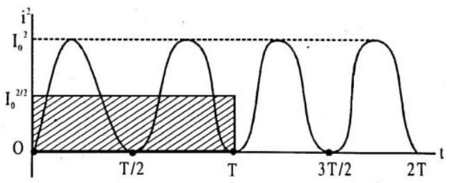
Fig. 7.42
It’s square root gives the root-mean-square (rms) current, i.e.,
Similarly, the root-mean-square (rms) value of a sinusoidal voltage is
When a sinusoidal current
which also equals the rate of heating, when a dc of the value
The currents and voltages in the power distribution systems are always quoted in terms of their
i.e., the voltage varies between
ILLUSTRATION-7.6
If a domestic appliance draws
(a) the average current
(b) the average of the square of the current
(c) the current amplitude
(d) the supply voltage amplitude.
Show Answer
SOLUTION:
(a) The average of sinusoidal
(b) RMS value of current
(c)
(d)
ILLUSTRATION-7.7
What is the ratio of mean value over half cycle to r.m.s. value of A.C.?
Show Answer
SOLUTION:
We know that
(i) Sime period: She time taken by a.C. to ga through ane cycle of changes is called its period. It is given as
(ii) Phase : Phase is that properly of wave motion which tells us the position of the particle at any instant as as its direction of mation. It is measured either by the angle which the particle makes with the mean pasition ar by fraction of time period.
(iii) Phase Angle : Angle assaciated with the wave motion (sine ar casine) is called phase angle.
(iv) Lead: Out of the current and em.f the ane hawing greater phase angle will lead the ather e.g. in equation
(v) Lag: Out of current and emf the one hauing omaller phase angle will lag the ather. In the aboue equations, the emfl lags the current by
RESISTANCE OFFERED BY VARIOUS ELEMENTS (RESISTOR, INDUCTOR, CAPACITOR) TO A.C.
Alternating current in a circuit may be controlled by resistance, inductance and capacitance, while the direct current is controtred only by resistance.
(i) Impedance (Z)
In alternating current circuit, the ratio of e.m.f. applied and consequent current produced is called the impedance and is denoted by Z, i.e.,
Physically impedance of ac circuit is the hindrance offered by resistance alongwith either inductance or capacitance or both in the circuit to the flow of ac through it. Its unit is ohm.
(ii) Reactance
The hindrance offered by inductance or capacitance or both to the flow of ac in an circuit is called reactance and is denoted by
(iii) Admittance
The inverse of impedance is called the admittance and is denoted by
Its unit is ohm
IMPEDANCES AND PHASES OF AC CIRCUIT CONTAINING DIFFERENT ELEMENTS
As already pointed out that in an ac circuit the current and applied e.m.f.’s are not necessarily in same phase. The applied e.m.f. (E) and current produced
where
(i) Circuit containing only resitance
Consider a pure ohmic resistor (zero inductance) of resistance
Fig. 7.43
where
Comparing this with standard equation, we note that
Impedance of circuit,
(ii) Circuit contianing only inductance
Consider a pure inductor (zero ohmic resistance) of inductance
Fig. 7.44
Comparing this with standard equation, we know that
Hence we conclude that in a purely inductive circuit the current lags behind the applied voltage by an angle
Fig. 7.45
(iii) Circuit Containing only Capacitance:
Consider a capacitor of capacitance
Then the current through
Comparing this with standard equation, we find that
Fig. 7.46
Hence we conclude that in a purely capacitive circuit the current leads the applied e.m.f. by an angle
Fig. 7.47
CIRCUIT CONTAINING RESISTANCE, INDUCTANCE AND CAPACITANCE IN SERIES (SERIES LCR CIRCUIT)
Consider a circuit containing a resistance
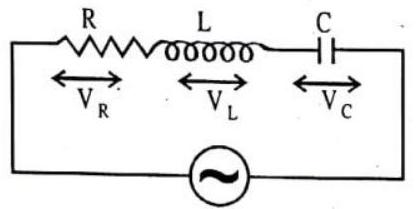
Fig. 7.48
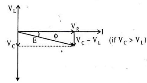
Fig. 7.49
i.e.,
The phase leads of current over applied e.m.f. is given by
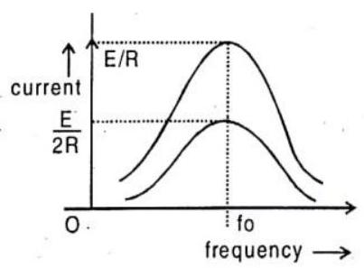
Fig. 7.50
i.e.,
It is concluded that
(a) If
(b) If
(c) If
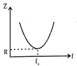
Fig. 7.51
Thus the resonant frequency depends on the product of
At resonance, impedance is minimum,
It is interesting to note that before resonance the current leads the applied e.m.f., at resonance it is in phase, and after resonance it lags behind the e.m.f.. LCR series circuit is also called as acceptor circuit and parallel LCR circuit is called rejector circuit.
ILLUSTRATION-7.8
Obtain the resonant frequency
Show Answer
SOLUTION:
Given,
By relation,
Quality factor (Q-value)
MISCELLANEOUS
SOLVED EXAMPLES
1. Two coils are wound on the same iron rod so that the flux generated by one also passes through the other. The primary has 100 loops and secondary has 200 loops. When a current of 2 A flows through the primary the flux in it is
Show Answer
SOLUTION:
2. A small coil of radius
(a)
(b)
(c)
(d)
Show Answer
SOLUTION: Let I be the current flow in the large coil.
Mag. flux linked with smaller coil
But
3. Find the self inductance of a coil in which an e.m.f. of
Show Answer
SOLUTION: Given :
Self inductance of coil
4. A conductor of length
Show Answer
SOLUTION: Given:
e.m.f. induced in conductor
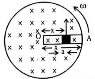
5. A metal rod of length
Show Answer
SOLUTION: Given:
In one rotation, the moving rod of the metal traces a circle of radius
6. A coil having 100 turns and area of 0.001 metre
Show Answer
SOLUTION: The flux linked with the coil when the plane of the coil is perpendicular to the magnetic field is
the change in flux on rotating the coil by
7. Predict the direction of induced current in the situations described by the following fig. 7.51 (a) to 7.51 (e)
Fig.7.52
Show Answer
SOLUTION: Applying Lenz’s law
(1) along
(4) along
(5) No induced current since field lines lie in the plane of the loop.
8. A uniform magnetic field
Show that the component of the induced electric field at
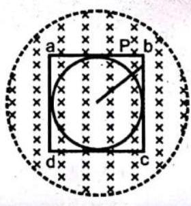
Fig. 7.53
Show Answer
SOLUTION: Flux in the circle is,
Emf induced is
Let the I. ectric field induced on the circumference is E. (
1 EXERCISE
Fill in the Blanks :
DIRECTIONS : Complete the following statements with an appropriate-word / term to be filled in the blank space(s).
1. A generator converts mechanical energy into ………….. energy.
It works on the basis of …………..
Show Answer
Answer: electrical, electromagnetic induction.2. In our houses we receive
Show Answer
Answer:3. The frequency for A.C. (alternating current) in USA is …………..
Show Answer
Answer:4. The armature in a motor rotates within
Show Answer
Answer: magnetic5. To produce DC, the output of a generator must be fed through a(n) …………..
Show Answer
Answer: commutator6. In any generator, the current in the armature is of the ………….. type.
Show Answer
Answer: A.C7. The phenomenon of production of back e.m.f. in a coil due to flow of varying current through it is called …………..
Show Answer
Answer: self-induction8. The unit of self-inductance in SI system is …………..
Show Answer
Answer: henry9. An e.m.f. is induced in a coil when ………….. linked with it changes.
Show Answer
Answer: the magnetic flux10. In an
Show Answer
Answer:11. A step down transformer steps up ………….. and steps down …………..
Show Answer
Answer: current, voltage12.
Show Answer
Answer: slip rings with split rings13. A transformer increases or decreases ………….. voltage.
Show Answer
Answer: A.C.14. Induced currents produced in a solid core placed in changing magnetic field is called an …………..
Show Answer
Answer: eddy currentTrue / False
DIRECTIONS : Read the following statements and write your answer as true or false.
1. An electric motor converts mechanical energy into electrical energy.
Show Answer
Answer: False2. An electric generator works on the principle of electromagnetic induction.
Show Answer
Answer: True3. In a DC electric motor a pair of split rings is used as commutator.
Show Answer
Answer: True4. A transformer is an electrical device that works on the principle of self-induction.
Show Answer
Answer: False5. Lenz’s law is used to find out the magnitude of the induced e.m.f.
Show Answer
Answer: False6. The Lenz’s law is consistent with the law of conservation of energy.
Show Answer
Answer: True7. Faraday observed that an e.m.f is produced across a conductor when the number of magnetic lines of force associated with the conductor changes.
Show Answer
Answer: True8. The magnitude of e.m.f. induced in a circuit is inversely proportional to the rate of change of magnetic flux linked with circuit.
Show Answer
Answer: False9. Induced current will appear in such a direction that it opposes the change that produced it.
Show Answer
Answer: True10. Eddy current involves loss of energy in the form of heat.
Show Answer
Answer: True11. S.I. unit of magnetic flux is weber. It is a vector quantity.
Show Answer
Answer: False12. Energy stored in an inductor
Show Answer
Answer: False13. The number of magnetic lines of force crossing is called magnetic flux linked with the surface.
Show Answer
Answer: True14. When ever the magnetic flux linking a coil changes, then an e.m.f.. is induced in the magnet.
Show Answer
Answer: False15. The induced e.m.f. depends only the turns of the coil
Show Answer
Answer: False16. The magnitude of induced current can be increased by increasing the number of turns in coil.
Show Answer
Answer: True17. The magnitude of induced current can be increased by decreasing the speed of rotation of coil.
Show Answer
Answer: False18. The magnitude of induced current can be decreased by increasing the area of cross section of coil.
Show Answer
Answer: FalseVery Short Answer Questions :
DIRECTIONS : Give answer in one word or one sentence.
1. State Fleming’s right hand rule.
Show Answer
Answer: M, B, I are represented by thumb, forefinger and middle finger of the right hand.2. Give the relation between
Show Answer
Answer:3. State Lenz’s law.
Show Answer
Answer: The direction of the induced current is such that it opposes the very cause that produces it.4. What is the difference between an AC dynamo and a DC dynamo?
Show Answer
Answer: Produces5. Give the principle of transformer? State the types of transformer
Show Answer
Answer: Electromagnetic induction.
(i) step-up
(ii) step-down transformers.
6. Can we produce electricity from magnetism ?
Show Answer
Answer: Yes.7. Does the A.C. generator have any slip ring ?
Show Answer
Answer: The A.C. generator has two slip rings.8. State two factors on which the magnitude and direction of induced e.m.f. depend.
9. How would you demonstrate that a momentary current can be obtained by the suitable use of a magnet and a coil of wire? What is the source of energy associated with the current so obtained?
10. An altemating electric current has a frequency of 5 Hz. How many times does it change its direction in one second?
Show Answer
Answer: Frequency of an alternating current is11. What will be the frequency of an alternating current if its direction changes after every
Show Answer
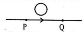
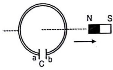
Answer:12. Give the direction of induced current in the wire loop, when the magnet moves forward as shown in the figure.

Show Answer
Answer: Anticlockwise from the side of the magnet.13. State Faraday’s law of electromagnetic induction.
Show Answer
Answer: According to Faraday’s law, the rate at which the magnetic flux changes gives induced e.m.f. The induced e.m.f. always opposes the change that brings it.14. Write S.I. unit of magnetic flux. Is it a scalar or a vector quantity?
Show Answer
Answer: S.I. unit of magnetic flux is weber. It is a scalar quantity.15. Define the term self inductance. Give its unit.
Show Answer
Answer: The self inductance of a coil is defined as the magnetic flux linked with the coil when unit current flows through it. S.I. unit is henry.16. If the number of turns in the solenoid is doubled, keeping other factors constant, how does the self inductance of the coil change?
Show Answer
Answer: Self inductance17. Write an expression for the energy stored in an inductor of inductance
Show Answer
Answer: Energy stored in an inductor18. If the rate of change of current is
Show Answer
Answer: Induced e.m.f.
19. A pure resistance is connected to an ac source of
Show Answer
Answer: In a pure resistive circuit the phase difference between current and the voltage is zero.20. A pure inductance is connected to an a.c. source of
Show Answer
Answer: In a pure inductor, the current lags behind the applied e.m.f. by21. A pure capacitor is connected to an ac source of
Show Answer
Answer: In a pure capacitive circuit, the current leads the voltage byShort Answer Questions :
DIRECTIONS : Give answer in two to three sentences.
1. Explain different ways to induce current in a coil.
Show Answer
Answer: (i) A current is induced in a coil when a magnet is moved relative to the fixed coil.
(ii) A-current is also induced in a coil when it is moved relative to a fixed magnet.
(iii) Not any current is induced in a coil when the coil and magnet both are stationary relative to one another.
(iv) When the direction of motion of magnet or coil is reversed, the direction of current induced in the coil also gets reversed.
2. State the rule to determine the direction of a (i) magnetic field produced around a straight conductor-carrying current, (ii) force experienced by a current-carrying straight conductor placed in a magnetic field which is perpendicular to it, and (iii) current induced in a coil due to its rotation in a magnetic field.
Show Answer
Answer: (i) The direction of magnetic field produced around a current-carrying conductor is given by right hand thumb rule. If the conductor carrying current is held in the right hand in such a way that the thumb points in the direction of current, then direction of curl of fingers gives the direction of the magnetic field.
(ii) The direction of force experienced by a straight conductor carrying-current placed in a magnetic field. which is perpendicular to it determined by Fleming’s left hand rule. Hold the thumb and first two fingers of the left hand at right angles to each other with the first finger pointing the direction of the field and the second finger in the direction of the current, then the thumb points in the direction of the motion.
(iii) The direction of current induced in a circuit by changing masenctic flux due to motion of a magnet is determined by Fleming’s right-hand rule, If we stretch our right hand in such a way that the thumb, forefinger and central finger remain perpendicular to echo other, so that the forefinger indicates the direction of the magnetic field and the thumb in the direction of motion of conductor. Then the central finger indicates the direction of induced current.
3. Explain the underlying principle of an electric generator. What is the function of brushes?
Show Answer
Answer: Principle : It is based on the principle of electromagnetic induction, which is the process of producing induced current in a coil by relative motion between a magnet and the coil. Function of brushes: The brushes carry the contact from rings to external load resistance.4. What is electromagnetic induction ? Describe one experiment to demonstrate the phenomenon of electromagnetic induction.
5. A flat rectangular coil is rotated between the pole pieces of a horse-shoe magnet. In which position of the coil with respect to the magnetic field, will the e.m.f. (i) be maximum (ii) be zero and (iii) change direction?
Show Answer
Answer: (i) The e.m.f. is maximum when the plane of the coil is parallel to the magnetic field.
(ii) The e.m.f. is zero when the plane of the coil is normal to the magnetic field.
(iii) The e.m.f. will change direction when the plane of coil passes from the position normal to the magnetic field.
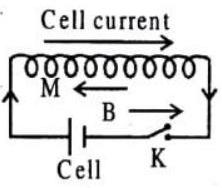
6. Two coils A and B are placed as shown in figure. The coil

(i) the key
(ii) the key
(iii) with the key
(iv) with the key
(v) with the key K closed, the coils A and B are moved away from each other.
Show Answer
Answer: As the key
(ii) As the key
(iii) With the key
(iv) With the key
(v) With the key
7. An induced e.m.f. has no direction of its own. Comment.
Show Answer
Answer: The given statement is correct. This is because, according to Lenz’s law, the direction of the induced e.m.f. is such as to oppose the cause of production of induced e.m.f.. Thus, the direction of induced e.m.f. is to be determined by the cause of e.m.f.8. Two coils are being moved out of magnetic field one coil is moved rapidly and the other slowly. In which case is more work done and why?
Show Answer
Answer: In the case of rapidly moving coil. Because induced e.m.f. will be more in the rapidly moving coil as compared to slowmoving coil. e.m.f. a work.9. A cylindrical bar magnet is kept along the axis of a circular coil and near it as shown in figure. Will there be any induced e.m.f. at the terminals of the coil, when the magnet is rotated (a) about its own axis and (b) about an axis perpendicular to the length of the magnet?
Show Answer
Answer: (a) When the magnet is rotated about its own axis, there is no change in the magnetic flux linked with the coil. Hence, no induced e.m.f. is produced in the coil.
(b) When the magnet is rotated about an axis perpendicular to its length. the orientation of the magnetic field due to the magnet will change continuously. Due to this, the magnetic flux linked with the coil will also change continuously and it will result in the production of induced e.m.f. in the coil.
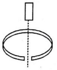
10. A bar magnet falls from a height ‘
Show Answer
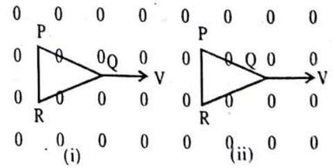
Answer: When the magnet falls, the magnetic flux linked through the metal ring changes, so current is induced in the ring will be in such a direction according to Lenz’s law that it opposes the motion of the magnet, so its acceleration will be less than11. The given figure shows two positions of a loop
Show Answer
Answer: In position (i), the coil remain in the magnetic field, so there is no change in magnetic flux in the coil. Therefore, no e.m.f. is induced in the coil.
In position (ii), the coil is coming out of the magnetic field, so the magnetic flux linked with it decreases and hence an e.m.f. is induced in the coil.
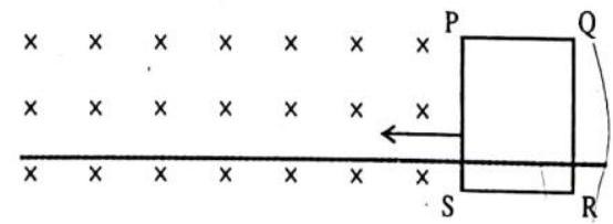
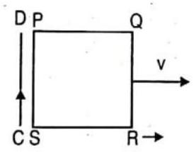
12.
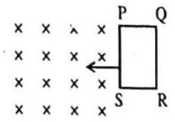
The closed loop PQRS is moving into a uniform magnetic field acting at right angles to the plane of the paper as shown. State the direction of the induced current in the loop.
Show Answer
Answer: The magnetic flux linked with the coil increases due to its motion. So by Lenz’s law, the induced current in the coil will oppose the increase in magnetic flux. So the magnetic field should be produced in upward direction and the induced current should be anticlockwise.13. A vertical metallic pole falls down through the plane of the magnetic meridian. Will any e.m.f. be produced between its ends? Give reason for your answer.
Show Answer
Answer: No e.m.f. will be produced between the ends of a metallic pole falling vertically through the plane of magnetic meridian as the falling pole does not cut any magnetic lines of force.14. The current through the wire
Show Answer
Answer: The electric current from15. In which direction will the current be induced in the closed loop if the magnet is moved as shown in the figure.
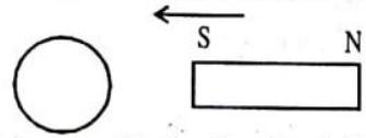
Show Answer
Answer: Since the south pole of the magnet is approaching towards the loop, so by Lenz’s law the induced current in the loop should be in such a direction that it should oppose the approach of the S-pole. So another S-pole should be produced at the near end of the coil. Therefore, the current should be in clockwise direction when viewed from the magnet side.16. A magnet is moved in the direction indicated by an \to between two coils
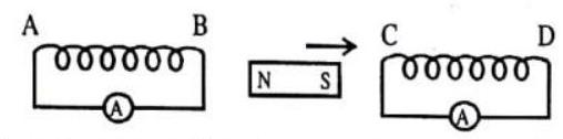
Show Answer
Answer: Induced current will be clockwise in both the coils, when viewed from the magnet side as the17. How does the self inductance of an air core coil change, when (i) the number of turns in the coil is decreased and (ii) an iron rod is introduced in the coil.
Show Answer
Answer: (i)
If number of turns
(ii) If an iron core is introduced in the coil, the permeability (m) increases, So self inductance also increases.
18. What is the difference between direct and alternating currents? Write one important advantage of using alternating current.
Show Answer
Answer: Differences between direct and alternating currents:
Direct current always flows in one direction only whereas alternating current reverses its direction periodically. Advantage of an alternating current: Alternating current can be transmitted over a long distances without loss of energy.
LONG ANSWER QUESTIONS :
DIRECTIONS : Give answer in four to five sentences.
1. What is induced e.m.f? Write Faraday’s law of electromagnetic induction. Explain it mathematically. A conducting rod of length
‘
Show Answer
Answer: Induced e.m.f: When the magnetic flux linked with a coil changes, an e.m.f is induced in the coil. This is called induced e.m.f.
Faraday’s law of electromagnetic induction:
1st Law: When the magnetic flux linked with a coil changes, an e.m.f is induced in the coil. It lasts so long as the change in flux continues.
2nd law: The magnitude of induced e.m.f is directly proportional to the rate of change of magnetic flux linked with the coil. It is in the opposite direction of the change of magnetic flux.
For a coil of
Induced e.m.f in a rotating rod:
consider a metallic rod of length 1 , which is rotating with angular velocity
2. What do you mean by mutual inductance of two nearby coils? Find an expression for mutual inductance of a solenoid-coil system.
Show Answer
Answer: When current flowing in one of two nearby coil is charged, the magnetic flux linked with the other coil changes, due to which an e.m.f. is induced in the other coil. This phenomenon is called mutual induction. The coil in which current is changed is called primary coil and the coil in which e.m.f. is induced is called secondary coil.
Suppose there are two coils
By experiment,
Where
From Faraday’s law,
induced e.m.f in secondary coil
If
Mutual inductance of a solenoid:
Consider a long solenoid of length 1 and number of turns
field produced within the solenoid is
3. Explain with the help of a diagram, the principle and working of an a.c. generator. Write the expression for the e.m.f. generated in the coil in terms of speed of rotation. Can the current produced by an a.c. generator be measured with a moving coil galvanometer.
Show Answer
Answer: 
Principle: A dynamo or generator is a device which converts mechanical energy into electrical energy. It is based on the principle of electromagnetic induction.
Construction: It consists of four main parts-
(i) Field magnet: It produces the magnetic field. For a low power dynamo, the magnetic field in generated by a permanent magnet but for a large power dynamo, the magnetic field is produced by an electromagnet.
(ii) Armature: It consists of a large number of turns of insulated copper wire on a soft iron core. It can revolve round the axis between the two poles of the field magnet. The soft iron core provides support to the coils and increases the magnetic field through the coil.
(iii) Slip rings: The slip rings
(iv) Brushes
Working: When the armature coil is rotated in the strong magnetic field, the magnetic flux linked the coil changes and the current is induced in the coil. The direction of current is given by Flemming’s left hand rule. It remains same during the first half turn of the armature. During the second half revolution, the direction of current is reversed. If
Therefore, the e.m.f. produced is alternating in nature and the current is also alternating.
Current produced in a.c. generator can not be measured by moving coil galvanometer, because average value of a.c. over full cycle is zero.
4. Derive an expression for the a.c. across a resistance
Show Answer
Answer:
Let
where
Graphical representation of voltage and current
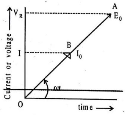
Phasor Diagram
The reflections of
5. What is impedance? Give its SI unit. Using the phasor diagram or otherwise derive an expression for the impedance of an a.c. circuit containing L, C and R in series. Find the expression for resonant frequency.
Show Answer
Answer: The obstruction posed by a circuit to the flow of a.c. is called its impedance
It’s S.I. unit is ohm.
Series L-C-R circuit:
Consider a resistance (R), inductance (L) and capacitance (C) are connected in series and an alternating source of voltage E =
Let the voltage across the resistance R is
So the phasors
But
The phase difference between voltage and current I can be given by the phase angle
where, tan
For resonance,
Also,
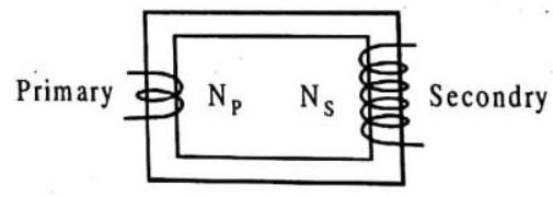
6. Show diagramatically two different arrangements used for winding the primary and secondary coils in a transformer. Assuming the transformer to be an ideal one, write expression for the ratio of it’s.
(i) Output voltage to input voltage
(ii) Output current to input current.
Mention the reasons for energy losses in an actual transformer.
Show Answer
Answer: The first arrangement is when two coils on top of each other.
The second arrangement is where two coils are wound on separate limbs of the core.
Ratio of output voltage to input voltage,
Ratio of output current to input current;
Energy losses in a transformer
1. Copper loss: Energy is lost as heat from the copper coils due to joule heating in the conducting wires.
2. Iron loss: Energy is lost as heat from the iron core of the transformer due to eddy current produced in the core. It can be minimised by the laminated core.
3. Leakage of magnetic flux: Due to this loss, magnetic flux linked with the primary will not be equal to that linked with secondary.
4. Hysteresis loss: Loss of heat energy due to repeated magnetisation and demagnetisation of the iron core.
5. Magnetostriction: Humming noise of a transformer.
Multiple Choice Questions :
DIRECTIONS : This section contains multiple choice questions. Each question has 4 choices (a), (b), (c) and (d) out of which ONLY ONE is correct.
1. Two identical coaxial circular loops carry a current
(a) the current in each increases,
(b) the current in each decreases,
(c) the current in each remains the same,
(d) the current in one increases whereas that in the other decreases
Show Answer
Answer: (b)2. An induced e.m.f. is produced when a magnet is plunged into a coil. The strength of the induced e.m.f. is independent of
(a) the strength of the magnet
(b) number of turns of coil
(c) the resistivity of the wire of the coil
(d) speed with which the magnet is moved
Show Answer
Answer: (c)3. Whenever the magnetic flux linked with a coil changes, an induced e.m.f. is produced in the circuit. The e.m.f. lasts
(a) for a short time
(b) for a long time
(c) for ever
(d) so long as the change in flux takes place
Show Answer
Answer: (d)4. A magnet is moved towards a coil (i) quickly (ii) slowly, then the induced e.m.f. is
(a) larger in case (i)
(b) smaller in case (i)
(c) equal in both the cases
(d) larger or smaller depending upon the radius of the coil
Show Answer
Answer: (a)5. Lenz’s law is a consequence of the law of conservation of
(a) charge
(b) mass
(c) energy
(d) momentum
Show Answer
Answer: (c)6. The laws of electromagnetic induction have been used in the construction of a
(a) galvanometer
(b) voltmeter
(c) electric motor
(d) generator
Show Answer
Answer: (d)7. A cylindrical bar magnet is kept along the axis of a circular. coil. On rotating the magnet about its axis, the coil will have induced in it
(a) a current
(b) no current
(c) only an e.m.f.
(d) both an e.m.f. and a current
Show Answer
Answer: (b)8. A moving conductor coil produces an induced e.m.f. This is in accordance with
(a) Lenz’s law
(b) Faraday’s law
(c) Coulomb’s law
(d) Ampere’s law
Show Answer
Answer: (b)9. A coil of insulated wire is connected to a battery. If it is taken to galvanometer, its pointer is deflected, because
(a) induced current is produced
(b) the coil acts like a magnet
(c) the number of turns in the coil of the galvanometer are changed
(d) none of the above
Show Answer
Answer: (a)10. A metal ring is held horizontally and bar magnet is dropped through the ring with its length along the axis of the ring. The acceleration of the falling magnet is
(a) equal to
(b) less than
(c) more than
(d) depends on the diameter of ring and length of magnet
Show Answer
Answer: (b)11. Whenever, current is changed in a coil, an induced e.m.f. is produced in the same coil. This property of the coil is due to
(a) mutual induction
(b) self induction
(c) eddy currents
(d) hysteresis
Show Answer
Answer: (b)12. Two pure inductors, each of self inductance
(a) L
(b) 2L
(c) L/2
(d) L/4
Show Answer
Answer: (c)13. Two coils of self inductances
(a)
(b)
(c)
(d)
Show Answer
Answer: (d)14. An inductor may store energy in
(a) its electric field
(b) its coils
(c) its magnetic field
(d) both in electric and magnetic fields
Show Answer
Answer: (c)15. If the number of turns per unit length of a coil of a solenoid is doubled, the self inductance of the solenoid will
(a) remain unchanged
(b) be halved
(c) be doubled
(d) become four times
Show Answer
Answer: (d)16. If
(a)
(b)
(c)
(d)
Show Answer
Answer: (c)17. Two coils of inductances
(a)
(b)
(c) The maximum value of
(d) The minimum value of
Show Answer
Answer: (d)18. The SI unit of inductance, henry, can be written as
(a) weber/ampere
(b) volt second/ampere
(c) joule/ampere
(d) all of these
Show Answer
Answer: (d)19. Two coils are placed close to each other. The mutual inductance of the pair of coils depends upon
(a) relative position and orientation of the two coils.
(b) the materials of the wires of the coils.
(c) the currents in the two coils
(d) the rates at which currents are changing in the two coils
Show Answer
Answer: (a)20. A capacitor acts as an infinite resistance for
(a) DC
(b)
(c) DC as well as
(d) neither
Show Answer
Answer: (a)21. An inductor, a resistor and a capacitor are joined in series with an
(a) of the inductor increases
(b) of the reasistor increases
(c) of the capacitor increases
(d) of the circuit increases
Show Answer
Answer: (a)22. An A.C. source is connected to a resistive circuit. What is true of the following
(a) current leads ahead of voltage in phase
(b) current lags behind voltage in phase
(c) current and voltage are in same phase
(d) any of the above may be true depending upon the value of resistance.
Show Answer
Answer: (c)23. The capacitive reactance in an A.C. circuit is
(a) effective resistance due to capacity
(b) effective wattage
(c) effective voltage
(d) none of the above
Show Answer
Answer: (a)24. The power factor in a circuit connected to an A.C. The value of power factor is
(a) unity when the circuit contians an ideal inductance only
(b) unity when the circuit contians an ideal resistance only
(c) zero when the circuit contains an ideal resistance only
(d) unity when the circuit contains an ideal capacitance only
Show Answer
Answer: (b)25. Current in a circuit is wattless if
(a) inductance in the circuit is zero
(b) resistance in the circuit is zero
(c) current is alternating
(d) resistance and inductance both are zero
Show Answer
Answer: (b)26. Power factor is one for
(a) pure inductor
(b) pure capacitor
(c) pure resistor
(d) either an inductor or a capacitor.
Show Answer
Answer: (c)27. Of the following about capacitive reactance which is correct
(a) the reactance of the capacitor is directly proportional to its ability to store charge
(b) capacitive reactance is inversely proportional to the frequency of the current
(c) capacitive reactance is mesured in farad
(d) the reactance of a capacitor in an A.C. circuit is similar to the resistance of a capacitor in a D.C. circuit
Show Answer
Answer: (b)28. With increase in frequency of an A.C. supply, the inductive reactance
(a) decrease
(b) increases directly proportional to frequency
(c) increases as square of frequency
(d) decreases inversely with frequency
Show Answer
Answer: (b)29. With increase in frequency of an A.C. supply, the impedance of an L-C-R series circuit
(a) remains constant
(b) increases
(c) decreases
(d) decreases at first, becomes minimum and then increases.
Show Answer
Answer: (d)30. For long distance transmission, the ac is stepped up because of high voltage, the transmission is
(a) faster
(b) economical
(c) undamped
(d) less dangerous
Show Answer
Answer: (c)31. The transformer voltage induced in the secondary coil of a transformer is mainly due to
(a) a varying electric field
(b) a varying magnetic field
(c) the vibrations of the primary coil
(d) the iron core of the transformer
Show Answer
Answer: (b)32. Eddy currents in the core of transformer can’t be developed
(a) by increasing the number of turns in secondary coil
(b) by taking laminated transformer
(c) by making step down transformer
(d) by using a weak a.c. at high potential
Show Answer
Answer: (b)33. The frequency of A.C. mains in India is
(a) 30 c/s
(b) 50 c/s
(c) 60 c/s
(d) 120 c/s
Show Answer
Answer: (b)34. Hot wire ammeters are used for measuring
(a) A.C. only
(b) D.C. only
(c) both A.C. and D.C.
(d) none of these
Show Answer
Answer: (c)35. Alternating current cannot be measured by D.C. ammeter because
(a) A.C. cannot pass through D.C. ammeter
(b) average value of current for complete cycle is zero
(c) A.C. is virtual
(d) A.C. changes its direction
Show Answer
Answer: (b)36. Alternating current is converted to direct current by
(a) rectifier
(b) dynamo
(c) transformer
(d) motor
Show Answer
Answer: (a)37. A transformer is employed to
(a) convert A.C. into D.C.
(b) convert D.C. into A.C.
(c) obtain a suitable A.C. voltage
(d) obtain a suitable D.C. voltage
Show Answer
Answer: (c)38. To convert mechanical energy into electrical energy, one can use
(a) DC dynamo
(b) AC dynamo
(c) motor
(d) (a) & (b)
Show Answer
Answer: (d)39. The AC voltage across a resistance can be meausred using
(a) a potentiometer
(b) a hot-wire voltmeter
(c) a moving-coil galvanometer
(d) a moving-magnet galvanometer
Show Answer
Answer: (b)40. A choke is preferred to a resistance for limiting current in A.C. circuit because
(a) choke is cheap
(b) there is no wastage of energy
(c) current becomes wattless
(d) current strength increases
Show Answer
Answer: (b)41. A choke coil has
(a) high inductance and high resistance
(b) low inductance and low resistance
(c) high inductance and low resistance
(d) low inductance and high resistance
Show Answer
Answer: (c)42. Transformers are used
(a) in DC circuit only
(b) in AC circuits only
(c) in both DC and AC circuits
(d) neither in DC nor in AC circuits
Show Answer
Answer: (b)43. A rectangular coil of copper wires is rotated in a magnetic field. The direction of the induced current changes once in each
(a) two revolutions
(b) one revolution
(c) half revolution
(d) one-fourth revolution
Show Answer
Answer: (c)44. The phenomenon of electromagnetic induction is -
(a) the process of charging a body.
(b) the process of generating magnetic field due to a current passing through a coil.
(c) producing induced current in a coil due to relative motion between a magnet and the coil.
(d) the process of rotating a coil of an electric motor.
Show Answer
Answer: (c)45. The device used for producing electric current is called a
(a) generator
(b) galvanometer
(c) ammeter
(d) motor
Show Answer
Answer: (a)46. The essential difference between an
(a)
(b)
(c)
(d)
Show Answer
Answer: (d)47. At the time of short circuit, the current in the circuit
(a) reduces substantially
(b) does not change.
(c) increases heavily
(d) vary continuously
Show Answer
Answer: (c)48. The direction of induced current is obtained by
(a) Fleming’s left hand rule
(b) Right hand thumb rule
(c) Biot and Savart rule
(d) Fleming’s right hand rule
Show Answer
Answer: (d)49. In an electric motor, conversion takes place of
(a) Chemical energy into electrical energy
(b) Electrical energy into mechanical energy
(c) Electrical energy into light
(d) Electrical energy into chemical energy
Show Answer
Answer: (b)50. The current in a generator armature is
(a) the magnetic field reverses at intervals
(b) the current in the field coils is
(c) the rotation of the armature causes the field through it to reverse
(d) the commutator feeds current into it in opposite directions every half cycle
Show Answer
Answer: (c)51. The current in the armature of a motor is reversed every half cycle due to the action of a(n)
(a) armature
(b) field coil
(c) brush
(d) commutator.
Show Answer
Answer: (d)52. For dynamo which one of the following statements is correct
(a) It converts the electrical energy into light energy
(b) It converts the kinetic energy into heat energy
(c) It converts the mechanical energy into electrical energy
(d) It converts the electrical energy into mechanical energy
Show Answer
Answer: (c)53. In an electric motor, the energy transformation is
(a) from electrical to chemical
(b) from chemical to light
(c) from mechanical to electrical
(d) from electrical to mechanical
Show Answer
Answer: (d)54. The direction of induced current is obtained by
(a) Fleming’s left hand rule
(b) Maxwell’s cork-screw rule
(c) Ampere’s rule
(d) Fleming’s right hand rule
Show Answer
Answer: (d)55. Which of the following has its working based on electromagnetic induction -
(a) Ammeter
(b) Volmeter
(c) Transformer
(d) Galvanometer
Show Answer
Answer: (c)56. A cylindrical bar magnet is kept along the axis of a circular coil. If the magnet is rotated about its axis, then -
(a) a current will be induced in the coil
(b) no current will be induced in the coil
(c) only emf will be induced in the coil
(d) an emf and current both will be induced in the coil
Show Answer
Answer: (b)57. Consider the arrangement shown in figure in which the north pole of a magnet is moved away from a thick conducting loop containing capacitor. Then excess positive change will arrive on
(a) plate a
(b) plate b
(c) on both plates
(d) on neither a nor b plates
Show Answer
Answer: (b)58. The north pole of a magnet is brought near a coil. The induced current in the coil as seen by an observer on the side of magnet will be
(a) in the clockwise direction
(b) in the anticlockwise direction
(c) initially in the clockwise and then anticlockwise direction
(d) initially in the anticlockwise and then clockwise direction
Show Answer
Answer: (a)59. Lenz’s law is consistent with law of conservation of -
(a) current
(b) canf
(c) energy
(d) all of the above
Show Answer
Answer: (c)60. When a magnet is being moved towands a coil, the indured emf does not depend upon
(a) the number of turns of the coil
(b) the motion of the magnet
(c) the magnetic moment of the magnet
(d) the resistance of the coil
Show Answer
Answer: (d)61. Consider the situation shown in figure. If the current
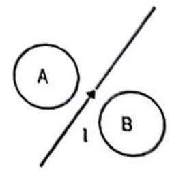 (a) clockwise in
 (b) anticlockwise in A, clockwise in B
(c) clockwise in both
(d) anticlockwise in both
Show Answer
Answer: (a)62. Direction of induced e.m.f. is determined by -
(a) Fleming’s left hand rule
(b) Fleming’s right hand rule
(c) Maxwell’s rule
(d) Ampere’s rule of swinming
Show Answer
Answer: (b)63. A magnet is brought towards a fixed coil rapidly. Due to this induced emf, current and charge are
(a) E increases
(b) I increases
(c) Q remains unchanged
(d)
Show Answer
Answer: (d)64. A square loop
(a) anticlockwise
(b) clockwise
(c) sometimes clockwise some times anticlockwise
(d) current will not be induced
Show Answer
Answer: (b)65. A thin sheet of conductor, when allowed to oscillate in a magnetic field normal to the sheet, then the motion is -
(a) damped due to air friction
(b) damped due to eddy currents
(c) accelerated due to eddy currents
(d) not effected by induced currents
Show Answer
Answer: (b)66. A small conducting rod of length
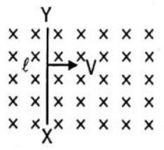
(a) Then the end
(b) the end
(c) the entire rod is unerringly charged
(d) the rod becomes hot due to joule heating
Show Answer
Answer: (b)67. The armature current in D.C. motor is maximum when the motor has -
(a) picked up maximum speed
(b) just started
(c) intermediate speed
(d) just been switched off
Show Answer
Answer: (a)68. A copper ring having a cut such as not to form a complete loop is held horizontally and a bar magnet is dropped through the ring with its length along the axis of the ring. Then acceleration of the falling magnet is -(neglect air friction)
(a)
(b) less than
(c) more than
(d) 0
Show Answer
Answer: (a)69. A metal sheet is placed in a variable magnetic field which is increasing from zero to maximum. Induced current flows in the directions as shown in figure. The direction of magnetic field will be -
(a) normal to the paper, inwards
(b) normal to the paper, outwards
(c) from east to west
(d) from north to south
Show Answer
Answer: (b)70. Three closed similar coils A, B and C are placed such that their planes are parallel. In the coil
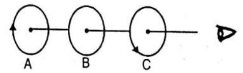
(a) clockwise current will be induced in coil B
(b) anti-clockwise current will be induced in coil
(c) no current will flow in coil B
(d) current induced in coil
Show Answer
Answer: (b)71. A conductor rod
(a) positively charged
(b) negatively charged
(c) neutral
(d) first positively charged and then negatively charged
Show Answer
Answer: (a)More Than One Carrect
DIRECTIONS : This section contains multiple choice questions. Each question has 4 choices
1. The reactance of a circuit is zero. It is possible that the circuit contains
(a) an inductor and a capacitor
(b) an inductor but no capacitor
(c) a capacitor but no inductor
(d) neither an inductor nor a capacitor
Show Answer
Answer: (a,d)2. In an AC series circuit, the instantaneous current is zero when the instantaneous voltage is maximum. Connected to the source may be a
(a) pure inductor
(b) pure capacitor
(c) pure resistor
(d) combination of an inductor and a capacitor
Show Answer
Answer: (a,b,d)3. An inductor-coil having some resistance is connected to an
(a) current
(b) induced e.m.f. in the inductor
(c) joule heat
(d) magnetic energy stored in the inductor
Show Answer
Answer: (a,b)4. The figure shows four wire loops, with edge lengths of either 
(a) I
(b) II
(c) III
(d) IV
Show Answer
Answer: (a,b)5. Figure shows a circuit with two resistors and an ideal inductor.
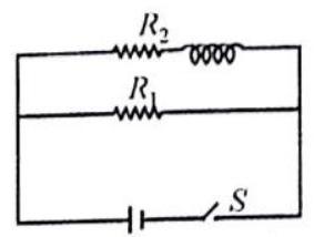
(a) The current in
(b) The current in
(c) The current in
(d) The currents in the resistors are maximum of their values a long time after closing the switch
Show Answer
Answer: (b,c,d)6.
(a)
(b)
(d)
(d)
Show Answer
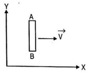
Answer: (b,c,d)7. A conducting loop is placed in a uniform magnetic field with its plane perpendicular to the field. An emf is induced in the loop if
(a) it is translated
(b) it is rotated about its axis
(c) it is rotated about its axis.
(d) it is expended
Show Answer
Answer: (c,d)8. If the inductance
(a) the current magnitude increases
(b) the maximum magnetic energy increases
(c) the maximum magnetic energy decreases
(d) current magnitude and maximum magnetic energy remain constant.
Show Answer
Answer: (a,b)9. An alternating e.m.f. of frequency
(a) The circuit is at resonance and its impedance is made up only of a reactive part
(b) The current in the circuit is in phase with the applied e.m.f. and the voltage across
(c) The sum of the p.d.’s across the inductance and capacitance equals the applied e.m.f. which is
(d) The quality factor of the circuit is
Show Answer
Answer: (b,d)10. The magnetic flux
(a) If
(b) If
(c) If
(d) If
Show Answer
Answer: (b,c,d)11. In which of the following cases does the electromagnetic induction occur -
(a) a current is started in a wire held near a loop of wire
(b) the current is stopped in a wire held near a loop of wire
(c) a magnet is moved through a loop of wire
(d) a loop of wire is held near a magnet
Show Answer
Answer: (a,b,c)Fill in the Passage :
DIRECTIONS : Complete the following statements with an appropriate word / term to be filled in the blank space(s).
increases,
……….1……… is a property of a coil due to which the coil opposes any chane in the strength of current flowing through it by inducting an e.m.f. in itself.
In the adjacent circuit shown, on closing the key
When the key is released, the current decreases from maximum to zero value in a certain time. Therefore, ……….5……… linked with the coil also decreases and an ……….6……… current is produced in the coil which will oppose the decay of current flowing in a direction ……….7……… to it.
Show Answer
Answer: 1. self induction, 2. gradually, 3. increases, 4. oppose, 5. magnetic flux, 6. induced, 7. oppositeprimary,
transfomation
Transformer is a device used to change an ……….1……… voltage from one to another of greater or smaller value. It is based on the principle of mutual induction.
A transformer consists of two sets of coils, insulated from each other. One of the coils called the primary coil has
If it is assumed that there is no energy loses, the input power is equal to output power.
voltage where
Show Answer
Answer: 1. alternating, 2. primary, 3. secondary, 4. transformation 5. transformerPassage Based Questions
DIRECTIONS : Study the given paragraph(s) and answer the following questions.
Passsage I
One application of LRC series circuit is to high pass or low pass filters, which filter out either the low or high frequency components of a signal. A high pass filter is shown in figure, where the output voltage is taken across the LR combination, where LR combination represents an inductance coil that also has resistance due to large length of the wire in the coil.
1. Find the ratio for
(a)
(b)
(c)
(d) 1
Show Answer
Answer: (b)2. Which of the following statements is correct when
(a)
(b)
(c)
(d)
Show Answer
Answer: (a)3. Which statement is correct in the limit of large frequency is reached? (For
(a) 1
(b)
(c)
(d)
Show Answer
Answer: (a)Passage II
Modern Trains are based on Maglev technology in which trains are magnetically leviated, which runs its EDS Maglev System. These are coils on both sides of wheels. Due to motion of train current induces in the coil of track which levitate it. This is in accordance with Lenz’s law. If trains lower down, then due to Lenz’s law a repulsive force increases due to which train gets uplifted and if it goes much high then there is a net downward force due to gravity. The advance of Maglev train is that there is no friction ebtween the trains and the track, thereby reducing power consumption and enabling the train to attain very high speeds. Disadvantage of Maglev train is that as it slows down the electromagnetic force decreases and it become difficult to keep it leviated and as it moves forwards, according to Lenz’s law there is an electromagnetic drop force.
1. What is the advantage of this system?
(a) No friction, hence no power consumption
(b) No electric power is used
(c) Gravitation force is zero
(d) Electrostatic force draws the train
Show Answer
Answer: (a)2. What is the disadvantage of this system?
(a) Train experiences an upward force according to Lenz’s law
(b) Friction force creates a drag on the train
(c) Retardation
(d) By Lenz’s law, train experiences a drag
Show Answer
Answer: (d)3. Which force causes the train to elevate up?
(a) Electrostatic force
(b) Time varying electric field
(c) Magnetic force
(d) Induced electric field
Show Answer
Answer: (c)Passsage III
A fresh man physics lab is designed to study the transfer of electrical energy from one circuit to another by means of a magnetic field using simple transformers. Each transformer has two coils of wire electrically insulated from each other but wound around a common core of ferromagnetic material. The two wires are close together but do not touch each other. The primary coil is connected to a resistor such as a light bulb. The AC source produces an oscilating voltage and current int he primary coil that produces an oscillating magnetic field in the core material. This in turn induces an oscilating voltage and AC current in the secondary coil. Students collected the following data comparing the number of turns per coil (N), the voltage (V) and the current (I) in the coils of three transformeers.
| Primary Coil | Secondary Coil | |||||
|---|---|---|---|---|---|---|
| Transformer 1 | 100 | 200 | ||||
| Transformer 2 | 100 | 50 | ||||
| Transformer 3 | 200 | 100 |
1. The primary coil of a transformer has 100 turns and is connected to a
(a) 5
(b) 50
(c) 200
(d) 2000
Show Answer
Answer: (d)2. A transformer with 40 turns in its primary coil is connected to a
(a)
(b)
(c)
(d)
Show Answer
Answer: (c)3. Which of the following is a correct expression for
(a)
(b)
(c)
(d)
Show Answer
Answer: (b)4. The primary coil of a given transformer has
(a)
(b)
(c)
(d)
Show Answer
Answer: (b)5. A
(a)
(b)
(c)
(d)
Show Answer
Answer: (a)Assertion & Reason :
DIRECTIONS : Each of these questions contains an Assertion followed by reason. Read them carefully and answer the question on the basis of following options. You have to select the one that best describes the two statements.
(a) Assertion is false, Reason is true
(b) Assertion is true, Reason is true; Reason is a correct explanation for Assertion
(c) Assertion is true, Reason is true; Reason is not a correct explanation for Assertion
(d) Assertion is true, Reason is false
1. Assertion : An induced e.m.f. appears in any coil in which the current is changing.
Reason : Self induction phenomenon obeys Faraday’s law of induction.
Show Answer
Answer: (b)2. Assertion : Lenz’s law violates the principle of conservation of energy.
Reason : Induced e.m.f. always opposes the change in magnetic flux responsible for its production.
Show Answer
Answer: (a) Lenz’s law (that the direction of induced e.m.f. is always such as to oppose the change that cause it) is direct consequence of the law of conservation of energy.3. Assertion : When number of turns in a coil is doubled, coefficient of self-inductance of the coil becomes 4 times.
Reason : This is because
Show Answer
Answer: (b)4. Assertion : An induced current has a direction such that the magnetic field due to the current opposes the change in the magnetic flux that induces the current.
Reason : Above statement is in accordance with conservation of energy.
Show Answer
Answer: (b)5. Assertion : The coil in the resistance boxes are made by doubling the wire.
Reason : Thick wire is required in resistance box.
Show Answer
Answer: (d)6. Assertion : When variable frequency a.c. source is connected to a capacitor, displacement current increases with increase in frequency.
Reason : As frequency increases conduction current also increases.
Show Answer
Answer: (b)7. Assertion : A capacitor blocks direct current in the steady state.
Reason : The capacitive reactance of the capacitor is inversely proportional to frequency
Show Answer
Answer: (b)8. Assertion : In the purely resistive element of a series LCR, AC circuit the maximum value of rms current increases with increase in the angular frequency of the applied e.m.f.
Reason :
where
Show Answer
Answer: (c)Multiple Maching Quesions :
DIRECTIONS : Following question has four statements
1. Column I gives some incomplete statements. Column II gives some completing statements. Match them correctly.
| Column I | Column II | |||
|---|---|---|---|---|
| (A) | A rod rotates in a uniform transverse magnetic field as shown, about hinge at |
(p) | may be zero | |
| (B) | A conducting loop is moved in a region of transverse constant magnetic field (infinite region), downward the plane of paper, as shown. Value of induced current |
(q) | must be zero | |
| (C) | If a constant force |
(r) | may be negative | |
| (D) | A square loop is rotated about diagonal in a region of uniform magnetic field as shown. Value of |
(s) | may be positive | |
| (t) | must be positive |
Show Answer
Answer: A-p,r,s; B-q; C-t; D-p,r,s
In case (C),
In Case
HOIS Subjective Questions :
DIRECTIONS : Answer the following questions.
1. If the self inductance of an iron core inductor increases from
Show Answer
Answer: Relative permeability
2. What is the magnitude of the induced current in the circular loop KLMN, of radius ‘

Show Answer
Answer: Since the current in wire
3. The following figure shows a horizontal solenoid ‘

Show Answer
Answer: As soon as the switch4. Name the main component which changes a.c generator in to d.c. generator.
Show Answer
Answer: Slipring arrangement in an a.c generator is replaced by split ring arrangement in the d.c generator.5. Write the expression for the efficiency of d.c. motor?
Show Answer
Answer: Efficiency,6. The series LCR circuit shown in the figure is in resonance Calculate the voltage across the inductor in terms of the source voltage and frequency.
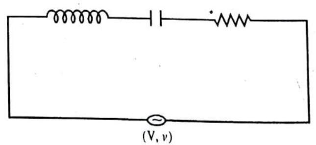
Show Answer
Answer: Current at resonance
7. In a transformer
Show Answer
Answer: There are three assumptions:-
(i) The primary resistance and current are small.
(ii) The same flux links both the primary and the secondary as very little flux escapes from the core.
(iii) The secondary current is small.
8. A bulb and capacitor connected in series to a source of ac. What will happen on increasing the frequency of the ac?
Show Answer
Answer: The bulb will glow brighter. As capacitative reactance is
The value of
9. Can a LCR circuit exhibit the phenomenon of electrical oscillation?
Show Answer
Answer: No, a circuit containing an inductor10. A bulb and an inductor are connected in series to a source of alternating current. What will happen on increasing the frequency of a.c. source?
Show Answer
Answer: The impedance of
As
11. What will be the effect on inductive reactance
Show Answer
Answer: Inductive reactance
Capacitive reactance
If
12. What is the phase difference between the voltage across the inductance and capacitor in an a.c circuit?
Show Answer
Answer: The phase difference is13. On what principle does a metal detector work?
Show Answer
Answer: The metal detector works on the principle of resonance in ac circuits.14. What is the value of power factor at resonance in LCR circuit?
Show Answer
Answer: At resonance,15. The divisions marked on the scale of an a.c. ammeter are not equally spaced. Why?
Show Answer
Answer: A.C. ammeter works on the principle of heating effect.16. How are eddy currents produced? Give two applications of eddy current.
Show Answer
Answer: When the magnetic flux linked with a conductor changes, a current is induced in the body of the conductor called eddy current. Eddy current is used for electromagnetic damping in dead beat galvanometer. It is used in Induction furnace to produce lot of heat sufficient to melt a metal.17. How does the mutual inductance of a pair of coils change when:
(i) the distance between the coils is increased?
(ii) the number of turns in each coil is dicreased? Justify your answer in each case.
Show Answer
Answer: (i) When the distance between the coils is increased the magnetic flux linked between them decreases as magnetic lines of force tend to diverge with distance. So mutual inductance also decreases.
(ii) If the number of turns in each coil is decreased then also mutual inductance decreases as mutual inductance is directly proportional to the number of turns.
18. The given figure shows an inductor
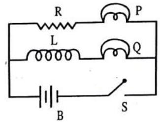
Show Answer
Answer: When the switch is closed the flux associated with19. In the diagram given, a coil
(i) Bulb lights and
(ii) Bulb gets dimme: if the coil ‘
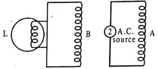
Show Answer
Answer: (i) When coil
(ii) When the coil B is moved upwards, distance between
20. A cyclindrical bar magnet is kept along the axis of a circular coil and near it as shown in the diagram will near be any induced e.m.f at the terminals of the coil, when the magnet is rotated (a) about its own axis, and (b) about an axis perpendicular to the length of the magnet?
Show Answer
Answer: In fig. (a), no change in magnetic flux takes place. Hence no e.m.f is induced in the coil.
In fig. (b), an e.m.f is induced in the coil as the magnetic flux is changed.
21. The closed loop