Chapter 06 Electromagnetism
Introduction
The term magnetism comes from Magnesia, the name of an ancient city in Asia Minor, where the Greeks found certain very unusual stones more than 2000 years ago. These stones, called lodestones, possess the unusual property of attracting pieces of iron. Such magnets were first fashioned into compasses and used navigation by the Chinese in the twelfth century A.D.
In the sixteenth century, William Gilbert, Queen Elizabeth’s physician, made artificial magnets by rubbing pieces of iron against lodestones. He suggested that a compass always points north and south because the earth itself shows the magnetic properties. Later in 1750, John Michaell in England found that magnetic poles obey the inverse-square law, and his results were confirmed by Charles Coulomb. The subjects of magnetism and electricity developed almost independently until 1:20, when a Danish physicist named Hans Christian Oersted discovered, in a classroom demonstration, that an electric current affects a magnetic compass. He saw that magnetism was related to electricity. Shortly thereafter, the French physicist Andre Marie Ampere proposed that electric currents are the source of all magnetic phenomena. This chapter is all about how electricity is connected with magnetism.
PERMANENT MAGNETS
Magnets produced from magnetic materials are called Artificial magnets. They can be made in a variety of shapes and sizes and are used extensively in electrical apparatus.
Artificial magnets are generally made from special iron or steel alloys which are usually magnetized electrically. The material to be magnetized is inserted into a coil of insulated wire and a heavy flow of electrons is passed through the wire. Magnets can also be produced by stroking a magnetic material with magnetite or with another artificial magnet. The forces causing magnetization are represented by magnetic lines of force.
Artificial magnets are usually classified as permanent or temporary, depending on their ability to retain their magnetic properties after the magnetizing force has been removed. Magnets made from substances, such as hardened steel and certain alloys which retain a great deal of their magnetism, are called permanent magnets. These materials are relatively difficult to magnetize because of the opposition offered to the magnetic lines of force as the lines of force try to distribute themselves throughout the material. The opposition that a material offers to the magnetic lines of force is called reluctance. All permanent magnets are produced from materials having a high reluctance.
A material with a low reluctance, such as soft iron or annealed silicon steel, is relatively easy to magnetize but will retain only a small part of its magnetism once the magnetizing force is removed. Materials of this type that easily lose most of their magnetic strength are called temporary magnets. The amount of magnetism which remains in a temporary magnet is referred to as its residual magnetism. The ability of a material to retain an amount of residual magnetism is called the retentivity of the material Magnets are also described in terms of the permeability of their materials, or the ease with which magnetic lines of force distribute themselves throughout the material. A permanent magnet, which is produced from a material with a high reluctance, has a low permeability. A temporary magnet, produced from a material with a low reluctance, would have a high permeability.
PROPERTIES OF BAR MAGNETS
(1) Attractive Property and Poles
When a magnet is dipped into iron fillings it is found that the concentration of iron filings, i.e., attracting power of the magnet is maximum at two points near the ends and minimum at the centre. The places in a magnet where its attracting power is maximum are called poles while the place of minimum attracting power is called the neutral region.
Fig. 6.2
(2) Directive Property and N-S Poles
When magnet is suspended its length becomes parallel to N-S direction. The pole pointing north is called the north pole while the other pointing south is called the south pole.
(3) Opposite poles (
Fig. 6.3
(4) Magnetic Axis and Magnetic Meridian
The line joining the two poles of a magnet is called magnetic axis and the vertical plane passing through the axis of a freely suspended or pivoted magnet is called magnetic meridian.
(5) Magnetic Length (
The distance between two poles along the axis of a magnet is called its effective or magnetic length. As poles are not exactly at the ends, the effective length is lesser than the actual length of the magnet.
Fig. 6.4
(6) Poles Exist in Pairs
In a magnet the two poles are found to be equal in strength and opposite in nature. If a magnet is broken into number of pieces, each piece becomes a magnet with two equal and opposite poles. This shows that monopoles do not exist.
Fig. 6.5
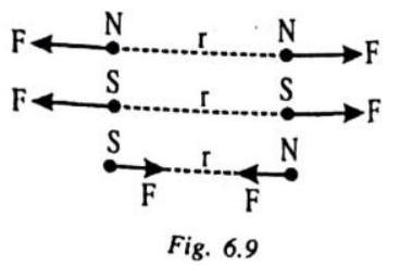
(7) Repulsion is a Sure Test of Polarity
A pole of a magnet attracts the opposite pole while repels similar pole. A sure test of polarity is repulsion and not attraction, as attraction can take place between opposite poles or a pole and a piece of unmagnetised magnetic material due to ‘induction effect’.
(8) Magnetic Induction
A magnet attracts certain other substances through the phenomenon of magnetic induction i.e., by inducing opposite pole in a magnetic material on the side facing it as shown in fig.
Fig. 6.6
IDEA BOX
- Fix a sheet of white paper on a drawing board using some adhesive material.
- Place a bar magnet in the centre of it.
- Sprinkle some iron filings uniformly around the bar magnet. A salt-sprinkler may be used for this purpose.
- Now tap the board gently.
- Note the observation.
Interesting Fact
Seeds of two tomatoes varieties Rocco and Monza were treated by passing them through an artificial magnetic field (MF) with a constant defined velocity before seeding. The seedlings obtained from MF treated and non MF-treated seeds were planted into the MF treated and non MF-treated plots. They were irrigated by MF-treated and non MF treated water.
Observations were made on early-yield, total-yield, beginning of blooming, and quality of fruit. While significant differences were not observed in Rocco, important MF effects were clearly seen on Monza. Yield increases on Monza in magnet treated plots were around
Pole strength and magnetic moment of a magnet
The strength of attracting a magnetic material by a magnetic pole is measured by pole strength, generally denoted by
The north and south poles of a magnet are said to be associated with the pole strengths
Fig. 6.7
The magnetic moment of a magnet is defined as a vector
where
MAGNETIC FIELD
The space around a magnet (or a current carrying conductor) in which its magnetic effect can be experienced is called the magnetic field. It is a quantity that has both direction and magnitude. Pictorically it is represented by magnetic lines of forces. Tangent to magnetic lines of forces gives direction of magnetic field at that point. No two magnetic lines of force intersect each other.
The magnetic field in a region is said to be uniform if the magnitude of its strength and direction is same at all points in that region.
Fig. 6.8
A magnetic field in a region is said to be uniform if the magnitude of its strength and direction is same at all the points in that region. The strength of magnetic field is also known as magnetic induction or magnetic flux density,
The SI unit of strength of magnetic field is Tesla (
1 Tesla
The cgs unit is gauss
COULOMB’S LAW IN MAGNETISM
This law defines the force
where
CHECK POINT
A friend tells you that a refrigerator door, beneath its layer of white-painted plastic, is made of aluminum. How could you check to see if this is true (without any scraping) ?
Show Answer
SOLUTION:
I will bring a magnet and make it touch with the refrigerator door. If the magnet shows a feeble attraction with it then I can say that it is aluminum.
ILLUSTRATION-6.1
Four identical bar magnets, each of magnetic moment
Show Answer
SOLUTION:
The magnetic moments of the given four identical bar magnets are acting along the sides of a square, as shown. The resultant of each of the two pairs of magnetic moments, i.e.,
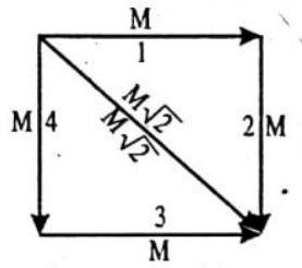
Fig. 6.10
MAGNETIC FIELD DUE TO MAGNETIC POLE
In SI, the magnetic induction
and direction away for north pole and towards for the south pole. In CGS, the magnetic field intensity
and direction away for the north pole and towards for the south pole.
FORCE ON MAGNETIC POLE PLACED IN MAGNETIC FIELD
In SI, the force a magnetic pole of strength
where + sign is for the north pole and - sign is for the south pole. Thus, the force is in the direction of
In CGS, the force on a magnetic pole of strength
where + sign is for the north pole and - sign is for the south pole. Thus, the force is in the direction of
MAGNETIC FIELD DUE TO A BAR MAGNET
End-on Position
The magnetic field
which is having the direction parallel to the magnetic moment
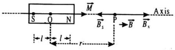
Fig. 6.13
Broadside-on Position
The magnetic field
which is having the direction antiparallel to the magnetic moment
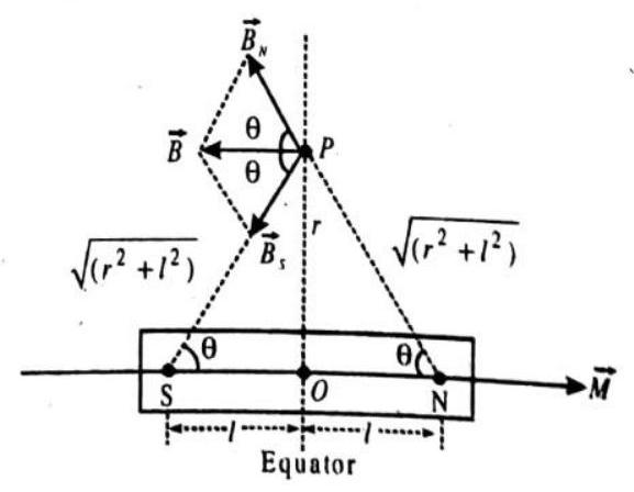
Fig. 6.14
Any Other Position
The magnetic moment
whose direction is inclined at an angle
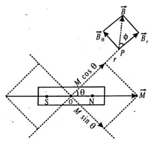
Fig. 6.15
FORCE AND TORQUE ON BAR MAGNET PLACED IN MAGNETIC FIELD
Uniform Magnetic Field
When a bar magnet is placed in a uniform magnetic field
and hence, it does not undergo any translatory motion.
The total torque on the bar magnet due to the magnetic field is
whose magnitude is
and whose direction is perpendicular to the plane of figure and inwards, as shown. This torque produces the rotatory motion of the bar magnet in the clockwise direction.
Non-uniform Magnetic Field
When the bar magnet is placed in a non-uniform magnetic field
which produces the translatory motion of the bar magnet in its’ direction.
The total torque on the bar magnet due to the magnetic field is
whose magnitude is
where
POTENTIAL ENERGY OF BAR MAGNET PLACED IN MAGNETIC FIELD
The potential energy of a bar magnet of the magnetic moment
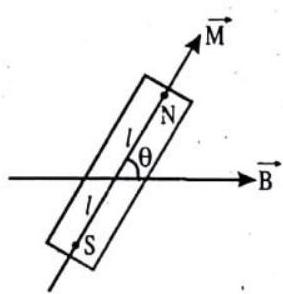
Fig. 6.18
where
WORK DONE IN ROTATING BAR MAGNET IN MAGNETIC FIELD
The work done in rotating a bar magnet of the magnetic moment
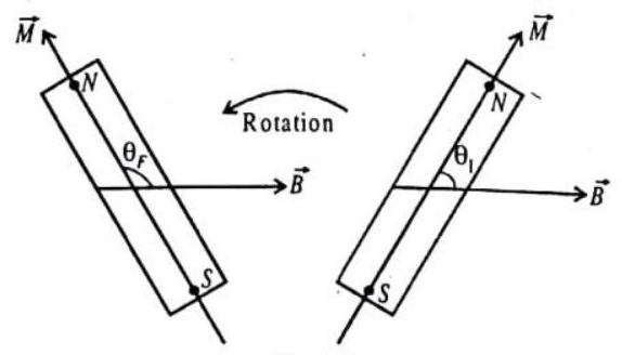
Fig. 6.19
For example, when the bar magnet is rotated through
CHECK POINT:
One way to make a compass is to stick a magnetized needle into a piece of cork and to float it in a glass bowl full of water. The needle will align itself with the horizontal component of the earth’s magnetic field. Since the north pole of this compass is attracted northward, will the needle float toward the north side of the bowl ? Defend your answer.
Show Answer
SOLUTION:
Yes, the north pole of the needle will float toward the north side of the bowl. The earth is a huge magnet whose north pole is towards the geographic south and the south pole is towards the geographic north. So, the north pole of the needle will align towards the south pole of the earth’s magnet which is northward. Therefore, the north pole of the needle will tend to float toward the north side of the bowl.
ILLUSTRATION-6.2
The magnetic field due to a small bar magnet at a distance of
SOLUTION:
The magnetic field due to the small bar magnet of the magnetic moment
The magnetic field at a distance
Dividing the two equations, we have
Terresterial Magnetism
William Gilbert suggested that earth itself behaves like a huge magnet. This magnet is so oriented that its
The earth behaves as a magnetic dipole inclined at small angle
(a) A freely suspended magnet always comes to rest in
The magnetic field at the surface of earth ranges from nearly
Cause of earth’s magnetism
Sir William Gilbert first suggested the existence of a powerful magnet inside the earth. This is not possible because.
(a) Temperature inside earth is so high that it will not be possible for magnet to retain magnetism.
(b) If there was a magnet inside the earth then position of earth’s magnetic poles would have not changed.
(c) The process of magnetisation of this magnet is not understood.
Grover suggested that earth’s magnetism is due to flow of current near outer surface of earth. These currents are produced due to sun. The hot air rising from regions near equator while going towards north and south hemispheres gets electrifield. These then magnetise ferromagnetic materials near the surface of earth.
According to another view earth’s core has many conducting materials like iron and nickel in molten state. Conventional currents are produced in this semi fluid core due to rotation of earth about its axis which generates magnetism.
Another view says magnetism is due to presence of ionised gases in atmosphere. The high energy sun rays ionize gas atoms in upper layer of atmosphere. The radioactivity of atmosphere and cosmic rays also ionize the gases. Strong electric currents flow due to rotation of earth producing magnetism.
Thus most likely cause of earth’s magnetism is the motion and distribution of charged materials in and outside the earth.
Some definitions
Geographic Axis
It is straight line passing through the geographic poles of the earth. It is the axis of rotation of the earth. It is known as polar axis.
Geographic Meridian
It is a vertical plane passing through geographic north and south poles of the earth.
Geographic Equator
A great circle on the surface of the earth in a plane perpendicular to geographical axis is called geographic equator. All places on geographic equator are at equal distances from geographical poles.
Magnetic Axis
It is a straight line passing through the magnetic poles of the earth. It is inclined to geographic axis at nearly
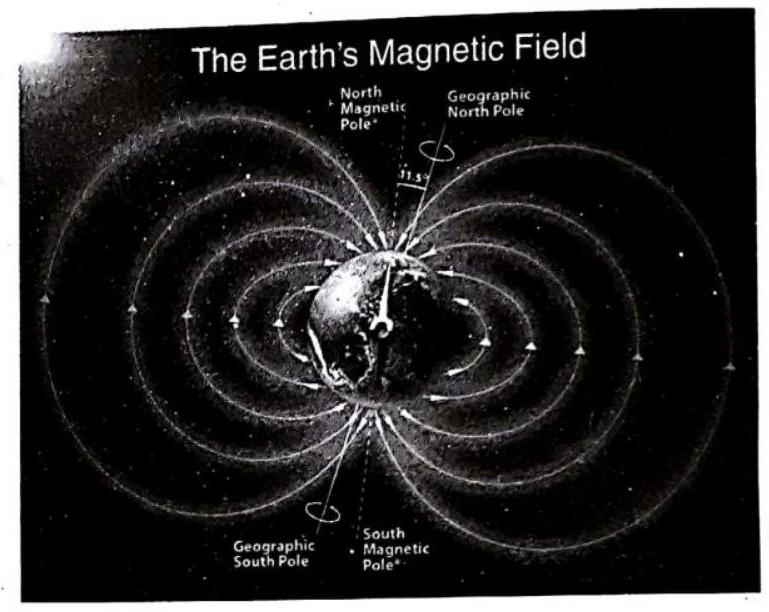
Fig. 6.20
Magnetic Meridian
It is a vertical plane passing through the magnetic north and south poles of the earth.
Magnetic Equator
A great circle on the surface of the earth in a plane perpendicular to magnetic axis is called magnetic equator. All places on magnetic equator are at equal distance from magnetic poles.
COMPONENTS OF EARTH’S MAGNETIC FIELD
The resultant magnetic field
The vertical component
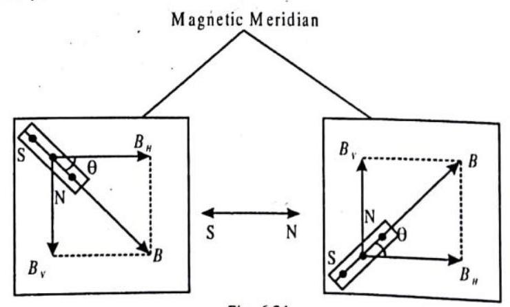
Fig. 6.21
Angle of Dip, or Inclination,
At a place, the angle
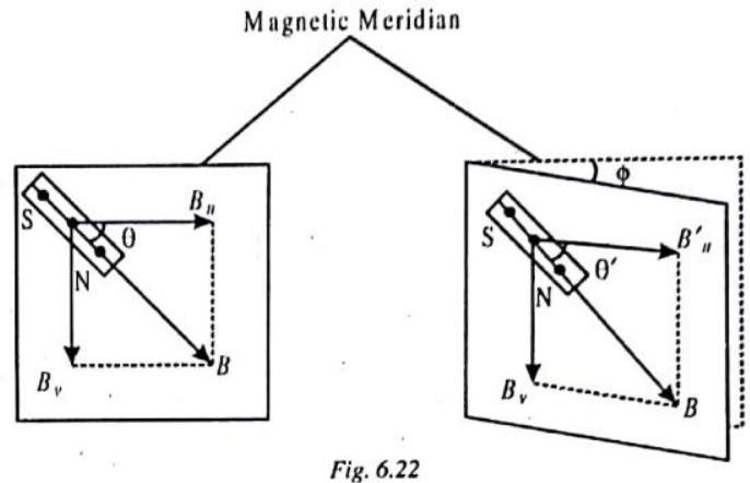
Variation, or Declination,
At a place, the angle
Magnetic Elements of Earth
The three parameters, namely, the angle of dip or inclination
declination
Magnetic Compass
Present day magnetic compasses use the same forces that guided ancient mariners. A magnetized needle, in conjunction with a compass card, rotates horizontally. Present day compasses are superior to the ancient ones through a heightened knowledge of magnetic laws and greater precision in construction.
The Earth’s magnetic lines of force provide the directional information needed to navigate. A compass detects and converts the energy from these magnetic lines of force into a directional display. In order to understand the operation of a ship’s compass, it is first necessary to understand some basic information about the Earth’s magnetic field.
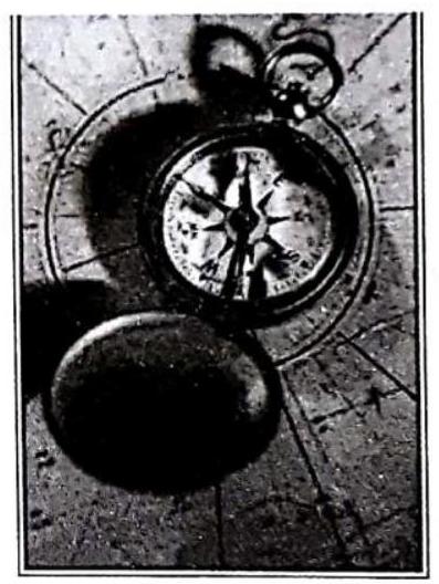
Fig. 6.23
Magnetism in medicine
An electric current always praduces a magnetic field. Euen weak ian currents that travel alang the nerwe cells in our body produce magnetic fields. When we touch something, our nerves carry an electric impulse ta the muscles we need to use. Shis impulse produces a temparary magnetic field. Shese ficlds are wery weak and are about ane-billionth of the earth’s magnetic field. Swa main argans in the human body where the magnetic field produced is oignificant, are the heart and the brain. The magnetic field inside the bady forms the basis of abtaining the images of different bady parts. This is done using a technique called Magnetic Resanance Imaging (MRJ). Analysis of these images helps in medical diagnosis. Magnetiom has, thus, gat impartant uses in medicine.
In research and industry, MRI is known as NMR - Nuclear Magnetic Resonance. II’s more or less the same process, but the medical establishment prefers the term MRI because some patients are scared off by the word nuclear.
The first MRI on a human was made in July 1977 by Dr. Raymond Damadian of New York. MRI patients are sometimen injected with gadolinium, a contrast agent that can make abnormalities such as tumors clearer due to the element’s npecial magnetic properties.
MRIs are most commonly used for cancer patients (about 35 percent of all scans) and patients with spinal problems (about
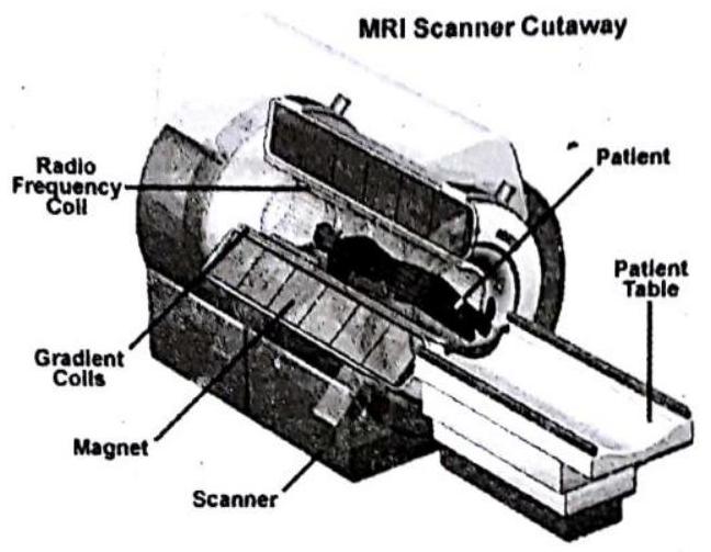
Fig. 6.24
NEUTRAL POINTS
Points where net magnetic field is zero are called neutral points.
Magnet in Horizontal Position
When a magnet is placed in the horizontal position with it’s north pole facing the north, we get the two neutral points
When the magnet is placed in the horizontal position with it’s north pole facing the south, we get the two neutral points
Magnet in Vertical Position
When the magnet is placed in the vertical position with it’s north pole resting on the table, we get only one neutral point
where,
Fig. 6.27
are the magnetic fields due to the two poles, taken separately.
When the magnet is placed in the vertical position with it’s south pole resting on the table, we get only one neutral point
where
are the magnetic fields due to the two poles.
Fig. 6.28
CHECK POINT:
Magnet
Show Answer
SOLUTION:
The magnet
ILLUSTRATION-6.3
A bar magnet of the length of
Show Answer
SOLUTION:
The two neutral points are situated in the end-on positions on the axis of magnet such that the magnetic field
MAGNETIC MATERIALS
Certain materials, when placed in a magnetising field
TERMS RELATED TO MAGNETISM
Magnetic intensity
When a magnetic material is placed in a magnetic field, it becomes magnetised. The capability of the magnetic field to magnetise a material is expressed by means of a magnetic vector
Intensity of magnetisation (I)
When a material is placed in a magnetising field, it acquires magnetic moment M. The intensity of magnetisation is defined as the magnetic moment per unit volume i.e.,
Magnetic Susceptibility
The magnetic susceptibility is defined as the intensity of magnetisation per unit magentising field i.e.,
Magnetic permeability
The magnetic permeability of a material is the measure of degree to which the material can be permeated by a magnetic field and is defined as the ratio of magnetic induction (B) in the material to the magnetising field i.e.
RELATION BETWEEN MAGNETIC SUSCEPTIBILITY AND PERMEABILITY
We have magnetic induction in mateiral, B =
Also
where
But
This is required relation.
CLASSIFICATION OF MATERIAIS
According to the behaviour of substances in magnetic field, they are classified into three categories
(I) DIAMAGNETIC SUBSTANCES
These are substances which when placed in a strong magnetic field acquire a feeble magnetism opposite to the direction of magnetising field.
The examples are copper gold, antimony, bismuth, alcohol, water, quartz, hydrogen, etc.
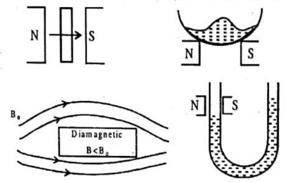
Fig. 6.29 : Behaviour of Diamagnetic substance in an external Magnetic Field
The characteristics of diamagnetic substances are
(a) They are feebly repelled by a strong magnet
(b) Their susceptibility is negative (i.e.
(c) Their relative permeability is less than 1. (i.e.
(d) Their susceptibility is independent of magnetising field and temperature (except for Bismuth at low temperature)
(II) PARAMAGNETIC SUBSTANCES
These are the materials which when placed in a strong magnetic field acquire a feeble magnetism in the same sense as the applied magnetic field. The examples are platinum, aluminium, chromium, manganese, 
Fig. 6.30 : Behaviour of Paramagnetic substance in an external field
The characteristics of paramagnetic substances are
(a) They are attracted by a strong magnet
(b) Their susceptibility is positive but very small
(c) Their relative permeability is slightly greater than unity.
(d) Their susceptibility and permeability do not change with the variation of magnetising field.
(e) Their susceptibility is inversely proportional to temperature,
(f) Found in those material which have atoms containing odd number of electrons
(III) FERROMAGNETIC SUBSTANCES.
These are the substances which are strongly magnetised by relatively weak magnetising field in the same sense as the magnetising field. The exarmples are
The characteristics of ferromagnetic substances are
(a) They are attracted even by a weak magnet.
(b) The susceptibility is very large and positive.
(c) The relative permeability is very high (of the order of hundreds and thousands). (
(d) The intensity of magnetisation is proportional to the magnetising field
(e) The susceptibility of a ferromagnetic substance is inversely proportional to temperature i.e.,
This is called Curie law. At a temperature called curie temperature, ferromagnetic substance becomes paramagnetic. The curie temperatures for
(f) Found in those material which have domains and can be converted into strong magnets
Keep in memory
1. Diamagnetism is universal. It is present in all materials. But it is weak and hard to detect if substance is para or feromagnetic
2.
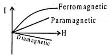
Fig. 6.31
3. Curve for magnetic susceptibility and temperature for a paramagnetic and ferromagnetic material.
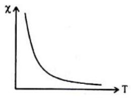
Fig. 6.32
HYSTERESIS
When a bar of ferromagnetic material is magnetised by a varying magnetic field and the intensity of magnetisation
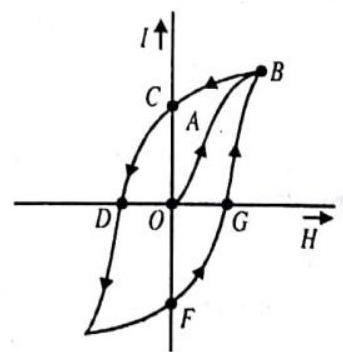
Fig. 6.33
(i) When magnetising field is increased from
(ii) When
(iii) When magnetic field
(iv) When field
(v) When
Properties of soft iron and steel
For soft iron, the susceptibility, permeability and retentivity are greater while coercivity and hysteresis loss per cycle are smaller than those of steel.

Permanent magnets are made of steel and cobalt while electromagnets are made of soft iron.
Oersted’s Experiment : An evidence of magnetic effect of current
After the invention of electric batteries, electric currents were a hot scientific topic, but no one suspected they had anything to do with magnetism. A Danish professor, Hans Christian Oersted, prepared for some friends, a science demonstration in his home. It included the heating of a wire by an electric current from a battery, and also some demonstrations of magnetism, using a compass on a stand. While carrying out the heating experiment, Oersted noted that every time he connected the current, the compass needle moved, too, something completely unexpected. No one else took notice. In the four months that followed he tried hard tc make sense of the phenomenon; but he couldn’t. The compass needle was neither attracted nor repelled, but tended to stand perpendicular to the wire.
Following Oersted’s article, the effect was confirmed by Andre-Marie Ampere, he felt that if a current in a wire exerted a magnetic force on a compass needle, two such wires also should interact magnetically. In a series of ingenious experiments he showed that this interaction was simple and fundamental, parallel (straight) currents attract, anti-parallel currents repel. The force between two long straight parallel currents was inversely proportional to the distance between them and proportional to the intensity of the current flowing in each. Loops of current attract or repel like magnets, coils with many loops multiplied the magnetic force, and Ampere guessed that iron atoms were magnetic because electric currents (soon named “Ampere currents”) circulated in them.
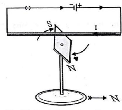
Fig. 6.35: Oersted’s experiment. Current in the wire deflects the compass needle.
CHECK POINT:
In figure, we see a magnet exerting a force on a current-carrying wire. Does a current-carrying wire exert a force on a magnet? Why or why n ?
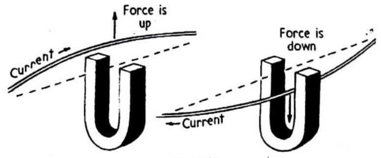
Fig. 6.36
Show Answer
SOLUTION:
Yes, a current-carrying wire also exert a force on a magnet. The current-carrying wire produces a magnetic field around it. When a magnet is brought near the wire, its magnetic field interacts with the magnetic field created by the wire. Duc to this interaction the magnet experiences a force.
BIOT-SAVART LAW
The Biot-Savart Law defines the magnetic field
The magnetic field at a point
where
and the direction of the cross product
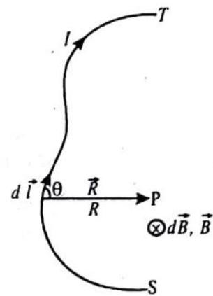
Fig. 6.37
MAGNETIC FIELD DUE TO A CURRENT CARRYING CONDUCTOR
From Oersted experiment followed by Ampere we can conclude that a magnetic field is developed around a conductor when electric current is passed through it. This observation is called magnetic effect of electric current. The presence of a current in a wire near a magnetic compass affected the direction of the compass needle. We now know that current gives rise to magnetic fields, just as electric charge give rise to electric fields.
Fig. 6.38 : Compass near a current-carrying wire
Straight conductor
The magnetic field around a conductor carrying current is in the form of closed circular loops, in a plane perpendicular to theconductor, and is given by right hand thumb rule.
Right hand thumb rule
If we grasp the conductor in the palm of the right hand so that the thumb points in the direction of the flow of current, then the direction in which the fingers curl, gives the direction of magnetic field lines.
Fig. 6.39
For the current flowing through the conductor in the direction shown in figures (a) or (b), the rule predict that magnetic field lines will be in anticlockwise direction, when seen from above.
This rule is also called Maxwell’s corkscrew rule. If we consider ourselves driving a corkscrew in the direction of the current, then the direction of the corkscrew is the direction of the magnetic field.
Ampere’s swimming rule
Imagine a man swimming along the wire, in the direction of current, (such that the current enters at his feet and leaves him at his head) and facing towards a compass needle placed underneath the wire, then the magnetic field produced is such that the north pole of the compass needle gets deflected towards his left hand.
Knowledge ENHANCER
Magnetic filed due to long straight conducotr
If the conductor is infinitely long then
or
If conductor is of infinite length but one end is in front of point P i.e. one end of conductor starts from point N then
Conductor is finite length and point P is just in front of middle of the conductor
CHECK POINT:
A beam of high-energy protons emerges from a cyclotron. Do you suppose there is a magnetic field associated with these particles? Why or why not?
Show Answer
SOLUTION:
Yes, I suppose there is a magnetic field associated with these particles. The particles are moving charged particles which produce a magnetic field.
ILLUSTRATION-6.4
Compute the magnetic field at a point of
Show Answer
SOLUTION:
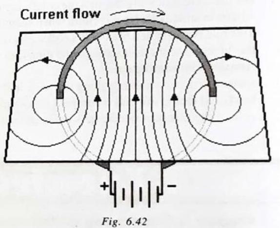
CIRCULAR LOOP
At every point of a current-carrying circular loop, the concentric circles representing the magnetic field around it would become larger and larger as we move away from the wire (Fig. 6.42). By the time we reach at the centre of the circular loop, the arcs of these big circles would appear as straight lines. Every point on the wire carrying current would give rise to the magnetic field appearing as straight lines at the center of the loop. By applying the right hand rule, it is easy to check that every section of the wire contributes to the magnetic field lines in the same direction within the loop.
Knowledge ENHANCER
Magnetic field at the centre of a circular current-carrying coil
For a coil of
Magnetic Field due to part of current carrying circular conductor (Arc)
Magnetic field on the axis of a circular coil
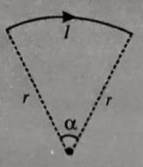
Fig. 6.43
At the centre of the loop,
In terms of area
Magnetic dipole moment of the current loop
The current loop can be regarded as a magnetic dipole which produces its magnetic field and magnetic dipole moment of the current loop is equal to the product of ampere turns and area of current loop, we can write
If the observation point is far away from the coil, then a « x S0.
In terms of magnetic dipole moment
RIGHT HAND PALM RULE
If we hold the thumb of right hand mutually perpendicular to the grip of the fingers such that the curvature of the finger represents the direction of current in the wire loop, then the thumb of the right hand will point in the direction of magnetic field near the centre of the current loop.
Fig. 6.45
ILLUSTRATION-6.5
An infinite straight conductor carrying current
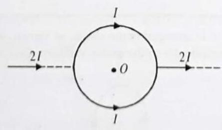
Fig. 6.46
Show Answer
SOLUTION:
Here, the wire does not produce any magnetic field at
ILLUSTRATION-6.6
A current of
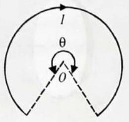
Fig. 6.47
Show Answer
SOLUTION:
ILLUSTRATION-6.7
A conducting wire of infinite length, carrying a current
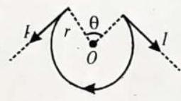
Fig. 6.48
Show Answer
SOLUTION:
The magnetic field at the centre
which is perpendicular to the plane of figure and outwards, according to the ‘Right-Hand Rule’. The magnetic field at the centre
which is perpendicular to the plane of figure and inwards, according to the ‘Modified Right-Hand Rule’. Then, the resultant
magnetic field at the centre
ILLUSTRATION-6.8
A long conducting wire, carrying a current
Fig. 6.49
Show Answer
SOLUTION:
The magnetic field at the centre
which is perpendicular to the plane of figure and outwards, according to the ‘Right-Hand Rule’. The magnetic field at the centre
which is parallel to the straight segments and towards right. Since, the two magnetic fields
FORCE ON A CHARGED PARTICLE IN A MAGNETIC FIELD
According to Lorentz, charge particle
Force,
The force
A charged particle at rest in a steady magnetic field does not experience any force.
If the charged particle is at rest then
A moving charged particle does not experience any force in a magnetic field if its motion is parallel or antiparallel to the field. i.e., if
then,
Fig. 6.50
If the particle is moving perpendicular to the field.
In this situation all the three vectors
Then
The force will be maximum
Work done by force due to magnetic field in motion of a charged particle is always zero.
When a charged particle move in a magnetic field, then force acts on it is always perpendicular to displacement,
so the work done,
And as by work-energy theorem
However, in this situation the force changes the direction of motion, so the direction of velocity
The direction of the cross product can be obtained by using a right-hand rule:
Fingers of the right hand point in the direction of the first vector
Fig. 6.51 : Magnetic force acting on a moving charge
A charged particle moving in a plane perpendicular to a magnetic field will move in a circular orbit with the magnetic force playing the role of centripetal force. The direction of the force is given by the right-hand rule. Equating the centripetal force with the magnetic force and solving for
Fig. 6.52 : Orbit of charged particle in a magnetic field.
If charge particle projected at some angle with magnetic field it will move on helical path as shown.
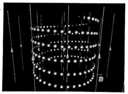
Fig. 6.53 : Helical path.
ILLUSTRATION-6.9
A magnetic field of
Show Answer
SOLUTION:
As the particle is moving in the
Comparing the coefficients of unit vectors of both sides, we have
and then, the velocity of particle is given by
ILLUSTRATION-6.10
A charge of
Find the magnetic force on the charge.
Show Answer
SOLUTION:
As the charge is moving with a speed of
and then, the magnetic force on the charge will be
Knowledge ENHANCER
VELOCITY SELECTOR :
Fig. 6.65 : Velocity selector for charged particles
An electric field and a magnetic field placed at right angles to each other can function as a “velocity selector.” When force up = force down, the charge will travel in a straight (horizontal) line. The speed can be obtained from the equation
Charged particles leaving a velocity selector (with a known velocity) can be inserted into a chamber with a magnetic field as shown.
In the circular orbit equation above
We can substitute
from which we can solve for
Fig. 6.54 : Mass spectrometer.
Force on a current carrying conductor in a magnetic field
Similar to the force on a moving charge in a
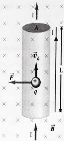
Fig. 6.55 : Force on a moving charge in a current-carrying conductor.
Direction of force can be determined by fleming’s left hand rule, right hand palm rule or screw rule.
Fleming’s Left-hand Rules
Stretch the fore-finger, central finger and thumb of left hand mutually perpendicular.
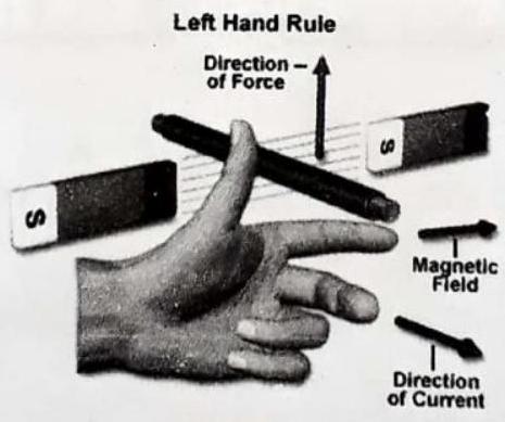
Fig. 6.56
Then if the fore-finger points in the direction of field
(ii) Right-hand Palm Rule
Stretch the fingers and thumb of right hand at right angles to each other. ihen if the fingers point in the direction of field
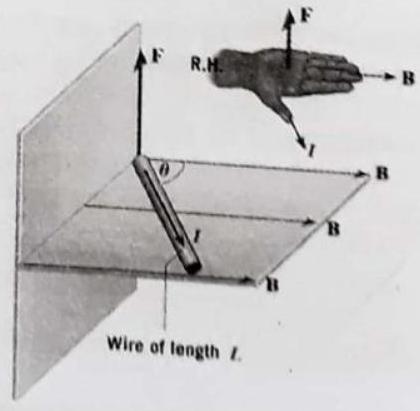
Fig. 6.57
To understand it in better manner see three figures.
Fig. 6.58
If no current is flowing through the wire obviously the force will be zero, if current is flowing upward using right hand rule( field inward shown by x) you will find force will act in left direction, hence wire will deflect as shown and if direction of current is downward force will try to move the wire in right direction and will deflect the wire as shown. Screw rule: Curl right hand finger from current towards magnetic field thumb will direction of force as shown in figure.
Fig. 6.59 : Magnetic force on straight wire segment.
You can see component of magnetic field perpendicular to current contributes in force on conductor. If current in wire is along external magnetic field force will be zero and if perpendicular to field it will be maximum.
Fig. 6.60
If direction of current or field reverses direction of force also reverses as shown in figure 6.61
Fig. 6.61 : Magnetic forces - reversing the direction of the B field or the direction of the current I reverses the direction of the force.
Ay arbitrary shape in a uniform field experience a force
where
If the current-carrying conductor in the form of a loop of any arbitrary shape is placed in a uniform field, then,
Here it must be kept in mind that in this situation different parts of the loop may experience elemental force due to which the loop may be under tension or may experience a torque as shown in figure 6.62 (b).
Fig. 6.62
CURRENT LOOP IN A UNIFORM FIELD
If a current-carrying conductor is situated in a non-uniform field, its different elements will experience different forces; so in this situation,
Fig. 6.63
ILLUSTRATION-6.11
A vertical straight conductor
Show Answer
SOLUTION:
(i) Here L = 0.5 m, B = 0.1 T, I = 4 A, F = ?
F = BIL =
(ii) Let
The force on the conductor
Fig. 6.64
ILLUSTRATION-6.12
A rectangular loop of sides
Show Answer
SOLUTION:
Consider a rectangular loop PQRS placed near a long straight conductor AB as shown in Figure 6.65. Due to the interaction of currents, the arm PQ of the loop will get attracted while arm RS will get repelled. Forces on the arms QR and SP will be equal and opposite and hence cancel out.
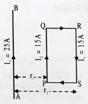
Fig. 6.65
Here,
Distance of
Distance of RS from
Current through long wire
Current through rectangular loop,
Force on the arm RS,
(towards AB)
FORCE BETWEEN CURRENT CARRYING WIRES
If currents are in the same direction, wires attract. If in opposite direction, wires repel. This is the opposite of the rule for charges: like charges repel, opposite charges attract. Using the two right hand rules, one for finding the direction of the B-field of a wire, and the other for the direction of force on a wire, you can predict the results.
Fig. 6.66
The force per unit length on one wire due to other wire
[Where
Experimental Demonstration

Definition of Ampere
When
This leads to the following definition of ampere.
One ampere is that current which, if passed in each of two parallel conductors of infinite length and one metre apart in vacuum causes each conductor to experience a force of
ILLUSTRATION-6.13
Calculate the magnetic force per unit length experienced by a long straight wire
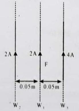
Fig. 6.68
Show Answer
SOLUTION:
The wire
The wire
Since, both magnetic forces on the wire
ELECTROMAGNET
A magnetic field is produced when an electric current flows through a coil of wire. This is the basis of the electromagnet. We can make an electromagnet stronger by doing these things:
wrapping the coil around an iron core
adding more turns to the coil
increasing the current flowing through the coil.
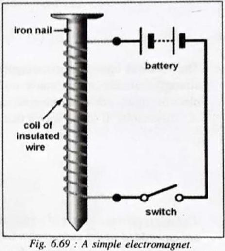
The magnetic field around an electromagnet is just the same as the one around a bar magnet. It can, however, be reversed by turning the battery around. Unlike bar magnets, which are permanent magnets, the magnetism of electromagnets can be turned on and off just by closing or opening the switch.
Uses of electromagnet
1. For lifting and transporting large masses of iron scrap, girders, plates etc., especially to places where it is not convenient to take the help of human labour. Electromagnets are used to lift as much as 20-22 tonnes of iron in a single lift. To unload the magnet at the desired place, the current in the electromagnet is switched off so that the load drops. 2. For loading furnaces with iron. 3. For separating magnetic substances such as iron from other debris (e.g. for separating iron from the crushed copper ore in copper mines). 4. For removing pieces of iron from wounds. 5. In several electrical devices such as electric-well, telegraph, electric tram, electric motor, relay, microphone, load speaker, etc. 6. In scientific research to study the magnetic properties of a substance in a magnetic field.
Fig. 6.70 : Electric Crane.
Some useful devices based on electromagnets produced by currents passing through solenoids
Electric bell
Parts of an electric bell
P - Push button, E - Electromagnet, A - Soft iron armature, S - Flexible metal strip, C - Contact screw, H - Hammer, G - Gong
When the push button
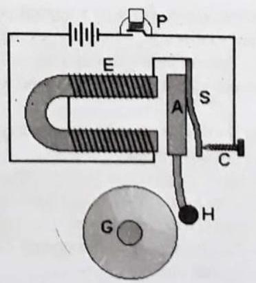
Fig. 6.71
Telephone
A typical telephone handset consists of two parts - the receiver (that you place next to your ear) utilises an electromagnet, and a microphone, into which you speak.

Fig. 6.72
The receiver has an electromagnet, B, connected to the circuit. Varying strengths of the current cause different amount of magnetisation of the electromagnet. The electromagnet causes deformation of the steel membrane, A. This results in sound waves that are picked up by the user’s ear.
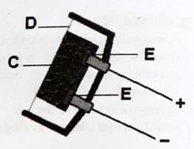
Fig. 6.73
The microphone consists of a steel membrane, D, lying across a small container of carbon powder, C. Two electrical contacts, E are embedded in the carbon powder, whose resistance depends on the density of the powder particles. Sound waves compress the powder to varying degrees, thus altering the resistance of the carbon powder. This in turn causes small changes in the current flowing through the circuit.
Loudspeaker
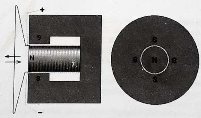
Fig. 6.74
A loudspeaker consists of a central pole, surrounded by a ring magnet, A movable coil, is wound around the central pole. Attached to this coil, which carries the current, is a cardboard cone.
When a current passes through the coil, a force acts on the coil forcing it to move in and out. The paper cone which is attached Relays to it moves with it, and sets up sound waves, which reproduce the sounds which a microphone originally converted to a current.
Relays
A relay is a device whereby a secondary circuit can be switched on by a primary circuit.
Referring to the diagram above, when the switch
Fig. 6.75
DC MOTOR
A d.c. motor converts direct current energy from a battery into mechanical energy of rotation.
Principle :
It is based on the fact that when a coil carrying current is held in a magnetic field, it experiences a torque, which rotates the coil.
Construction :
It consists of the five parts.
Armature :
The armature coil ABCD consists of a large number of turns of insulated copper wire wound over a soft iron core, Field Magnet : The magnetic field is supplied by a permanent magnet
Split-rings or Commutator :
These are two halves of the same ring. The ends of the armature coil are connected to these halves which also rotate with the armature.
Brushes :
These are two flexible metal plates or carbon rods
Battery :
The battery consists of a few cells of voltage
Working :
The battery sends current through the armature coil in the direction shown in figure. Applying Fleming’s Left Hand Rule,
Fig. 6.76
Efficiency of the d.c. motor :
Since the current
According to Joule’s law of heating, Power lost in the form of heat in the coil
If we assume that there is no other loss of power, then Power converted into external work i.e.,
Output mechanical power
A d.c. motor delivering maximum output has an efficiency of only
Uses :
(1) The d.c. motors are used in d.c. fans (exhaust, ceiling or table) for cooling and ventilation.
(2) They are used for pumping water.
(3) Big d.c. motors are used for running tram-cars and even trains.
AC Motor
As in the DC motor case, a current is passed through the coil, generating a torque on the coil. Since the current is alternating, the motor will run smoothly only at the frequency of the sine wave. It is called a synchronous motor. More common is the induction motor, where electric current is induced in the rotating coils rather than supplied to them directly.
One of the drawbacks of this kind of AC motor is the high current which must flow through the rotating contacts. Sparking and heating at those contacts can waste energy and shorten the lifetime of the motor. In common AC motors the magnetic field is produced by an electromagnet powered by the same AC voltage as the motor coil. The coils which produce the magnetic field are sometimes referred to as the “stator”, while the coils and the solid core which rotates is called the “armature”. In an AC motor the magnetic field is sinusoidally varying, just as the current in the coil varies.
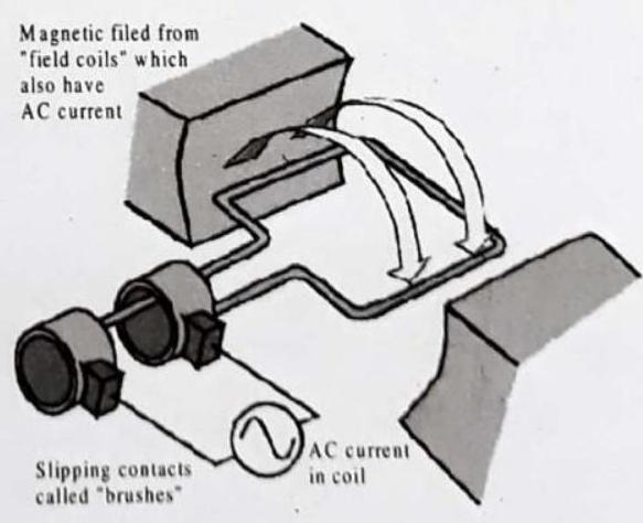
Fig. 6.77
Galvanometer
The torque on a current loop in a uniform magnetic field is used to measure electrical magnetic field is used to measure electrical currents. This current measuring device is called a moving coil galvanometer.
Fig. 6.78
The galvanometer consists of a coil of wire often rectangular, carrying the current to be measured. There are generally many turns in the coil to increase its sensitivity. The coil is placed in a magnetic field such that the lines of B remain nearly parallel to the plane of wire as it turns. This is achieved by having a soft iron cylinder placed at the center of the coil. Magnetic field lines tend to pass through the iron cylinder, producing the field configuration. The moving coil is hung from a spring which winds up as the coil rotates; this winding up produces a restoring torque proportional to the winding up (or twisting) of the spring, i.e. to the angular deflection of the coil. The coil comes to equilibrium when this restoring torque
CHECK POINT:
How could a light bulb near, yet not touching, an electromagnet be lit? Is AC or DC required? Defend your answer.
Show Answer
SOLUTION:
For the bulb to be lit,
MISCELLANEOUS
SOLVED EXAMPLES
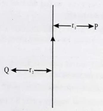
1. Two identical wires
Show Answer
SOLUTION: (i) Midway between
Field due to
Field due to
Direction of
(ii) If
Resultant field
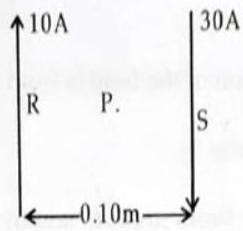
2. In the figure
Show Answer
SOLUTION: The force on the side PS due to current
The force on the side QR due to current through
The force on
Hence the net force
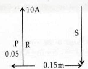
3. Calculate the magnetic flux density at a point
Show Answer
SOLUTION:
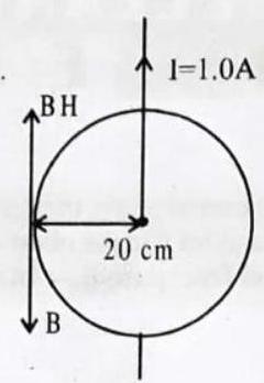
From the right hand grip rule, the direction of the field is from north to south and the horizontal component of the earth’s field is from south to north.
Hence the resulting magnectic flux density
4. A horizontal straight wire
Show Answer
SOLUTION:
Mass of the wire,
Resistance of the wire
R = (Resistance per unit length
Let
5. Two long parallel conductors carry respectively currents of 12 and 8A respectively in the same direction. If the wires are
Show Answer
SOLUTION: For the force on the third conductor to be zero, the direction of the flux density due to the current flowing in the two wires must be opposite in the position of the wire.
or
or
6. A rectangular loop of sides
Show Answer
SOLUTION: Consider a rectangular loop PQRS placed near a long straight conductor
Here,
Distance of PQ from
Distance of RS from
Current through long wire
Current through rectangular loop,
Force on the arm RS,
7. A narrow vertical rectangular coil is suspended from the middle of its upper side with its plane parallel to a uniform horizontal magnetic field of
Show Answer
SOLUTION:
Torque
New value of the torque when the plane of the vertical coil was at
Fill in the Blanks:
DIRECTIONS : Complete the following statements with an appropriate word / term to be filled in the blank space(s).
1. A compass needle is a …………….. magnet.
Show Answer
Answer: small2. Field lines are used to represent a ……………..
Show Answer
Answer: magnetic field3. Field lines are shown closer together where the magnetic field is ……………..
Show Answer
Answer: greater4. A metallic wire carrying an electric current has associated with it a …………….. field.
Show Answer
Answer: magnetic5. The field lines about the wire consist of a series of concentric circles whose direction is given by the …………….. rule.
Show Answer
Answer: right-hand6. The magnetic lines of force are the lines drawn in a magnetic field along which a …………….. pole would move.
Show Answer
Answer: north magnetic7. An electric current can be used for making temporary magnets known as ……………..
Show Answer
Answer: electromagnets8. The unit of magnetic field is ……………..
Show Answer
Answer: tesla9. The S.I. unit of magnetic flux ……………..
Show Answer
Answer: Weber10. The force between currents is called the …………….. force.
Show Answer
Answer: magnetic11. The N-pole of a compass points to the …………….. pole of a permanent magnet.
Show Answer
Answer: S12. The force that a magnetic field exerts on a current is always perpendicular to the …………….. and to the ……………..
Show Answer
Answer: field, current13. In a magnetic field pointing away from you, an electron traveling to the right will experience a force in the …………….. direction.
Show Answer
Answer: downward14. Magnetic fields are produced by ……………..
Show Answer
Answer: currents15. You are looking into a solenoid, at its S-pole, along its axis From your view point, the direction of the current in the solenoid is ……………..
Show Answer
Answer: clockwise16. Crowding the wires of a solenoid more closely together will …………….. the strength of the field inside it.
Show Answer
Answer: increase17. A paramagnet magnet behaves like a solenoid because both contain currents in the form of ……………..
Show Answer
Answer: circles18. Magnetic field lines emerge from the …………….. pole of a solenoid or a permanent magnet.
Show Answer
Answer: None19. You are looking down the axis of a solenoid, and the current from your position is clockwise. The end of the solenoid facing you is a …………….. pole.
Show Answer
Answer: southTrue / False :
DIRECTIONS : Read the following statements and write your answer as true or false.
1. Energy associated with an electric field is analogous to potential energy whereas the energy associated with the magnetic field is analogous to kinetic energy.
Show Answer
Answer: True2. No net force acts on a rectangular coil carrying a steady current when suspended freely in a uniform magnetic field.
Show Answer
Answer: True3. An electron and a proton move in a uniform magnetic field with same speed perpendicular to the magnetic field. They experience forces in opposite directions differing by a factor of 1840.
Show Answer
Answer: False4. A positive charge projected along the axis of a current carrying solenoid moves undeviated from its original path.
Show Answer
Answer: True5. There is no change in the energy of a charged particle moving in a magnetic field although a magnetic force is acting on it.
Show Answer
Answer: False6. An electron does not suffer any deflections while passing through a region. This makes sure that there is no magnetic field in that region.
Show Answer
Answer: True7. The field at the centre of a long circular coil carrying current will be parallel straight lines.
Show Answer
Answer: True8. A magnetic field exists in the region surrounding a magnet, in which the force of the magnet can be detected.
Show Answer
Answer: True9. The pattern of the magnetic field around a conductor due to an electric current flowing through it depends on the shape of the conductor.
Show Answer
Answer: True10. A current-carrying conductor when placed in a magnetic field always experiences a force.
Show Answer
Answer: False11. ‘Lodestone’ is a naturally occurring magnet.
Show Answer
Answer: True12. The direction of force on a current carrying conductor placed in a magnetic field can be reversed by reversing the direction of current flowing in the conductor.
Show Answer
Answer: True13. The direction of force on a current carrying conductor placed in a magnetic field cannot be reversed by reversing the direction of magnetic field.
Show Answer
Answer: False14. Two magnetic lines of force never intersect each other.
Show Answer
Answer: True15. The field lines inside the infinite solenoid are in the form of parallel straight lines.
Show Answer
Answer: TrueMatch the Following :
DIRECTIONS : Each question contains statements given in two columns which have to be matched. Statements
1.
| Column I | Column II | ||
|---|---|---|---|
| (A) | Work done by the magnetic force may be | (p) | zero |
| (B) | Work done by the pseudo force may be | (q) | |
| (C) | Frictional work | (r) | Conservative |
| (D) | Change in kinetic energy of charge particle in magnetic field. | (s) | Non conservative |
Show Answer
Answer:2. Column II gives approximate values of magnetic fields due to source given in column I
| Column I | Column II | ||
|---|---|---|---|
| (A) | At surface of neutron star | (p) | |
| (B) | Near big electromagnet | (q) | |
| (C) | At earth surface | (r) | |
| (D) | In interstellar space | (s) |
Show Answer
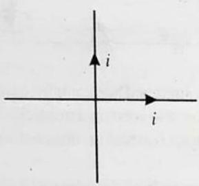
Answer:3. Equal currents i flow in two wires along
| Column I | Column II | ||
|---|---|---|---|
| (A) | Magnetic field in first quadrant | (p) | inwards |
| (B) | Magnetic field in second quadrant | (q) | outwards |
| (C) | Magnetic field in third quadrant | (r) | may be inwards or outwards |
| (D) | Magnetic field in fourth quadrant |
Show Answer
Answer:Very Short Answer Questions:
DIRECTIONS : Give answer in one word or one sentence.
1. Why does a compass needle get deflected when brought near a bar magnet?
Show Answer
Answer: A compass needle gets deflected when brought near a bar magnet because magnetic force is exerted by the bar magnet on the compass needle, which is itself a tiny pivoted magnet.2. A current through a horizontal power line flows in east to west direction. What is the direction of magnetic field at a point directly below it and at a point directly above it ?
Show Answer
Answer: The current is in the east-west direction. Applying the righthand thumb rule, we get that the direction of magnetic field at a point below the wire is from north to south. The direction of magnetic field at a point directly above the wire is from south to north.3. Why don’t two magnetic lines of force intersect each other?
Show Answer
Answer: Two magnetic lines of force never intersect each other. If the lines intersect, then at the point of intersection there would be two directions (the needle would point towards two directions) for the same magnetic field, which is no possible.4. Consider a circular loop of wire lying in the plane of the table. Let the current pass through the loop clockwise. Apply the right-hand rule to find out the direction of the magnetic field inside and outside the loop.
Show Answer
Answer: Direction of magnetic field inside the loop - Perpendicular to the plane of paper inward and Direction of magnetic field outside the loop-Perpendicular to the plane of paper outward.5. List three sources of magnetic fields.
Show Answer
Answer: (a) Natural and artificial magnets.
(b) Electromagnets
(c)
6. When is the force experienced by a current-carrying conductor placed in a magnetic field largest?
Show Answer
Answer: The force experienced by a current-carrying conductior placed in a magnetic field is largest when the direction of current is at right-angles to the direction of the magnetic field.7. What do you conclude from Oersted’s experiment?
Show Answer
Answer: Oersted’s experiment demonstrates the magnetic effect of current. It showed experimentally that the current flowing through a conductor produces a magnetic field.8. Name the types of electromagnets commonly used.
Show Answer
Answer: (i) Bar type
(ii) Horse shoe type
9. When can an electric charge give rise to a magnetic field?
10. Why is soft iron used as the core of the electromagnet used in electric bell?
11. How will the direction of force be changed, if the current is reversed in the conductor placed in a magnetic field?
12. Describe a set up for plotting the magnetic lines of force in a straight conductor.
13. What is the direction of magnetic field at the centre of a coil carrying current in (i) clockwise (ii) anticlockwise direction?
Show Answer
Answer: (i) Along the axis of the coil inwards
(ii) Along the axis of the coil outwards.
14. Why does a current carrying, freely suspended solenoid rest along a particular direction?
15. What constitutes the field of a magnet?
Show Answer
Answer: Magnetic field lines at any point constitute the field of a magnet indicating that a north pole experiences a force at that point16. Name the physical quantity whose S.I. unit is
Show Answer
Answer: Magnetic field. It is a vector quantity.17. Name the rule used to find the direction of force on a current carrying conductor.
Show Answer
Answer: Fleming’s left hand rule.18. What is the greatest disadvantage with a suspended-type moving coil galvanometer?
Show Answer
Answer: It is not portable.19. If the length of the suspension wire is increased does the sensitivity of a moving coil galvanometer increase or decrease?
Show Answer
Answer: Sensitivity increases.20. If a mirror of greater radius of curvature replaces the mirror of a moving coil galvanometer, does the sensitivity of the galvanometer, does the sensitivity of the galvanometer increase or decrease?
Show Answer
Answer: It remains unchanged.21. Why are the pole pieces of a galvanometer made concave?
Show Answer
Answer: The concave pole pieces provide a radial magnetic field, which is strong.Short Answer Questians :
DIRECTIONS : Give answer in 2-3 sentences.
1. State two ways through which the strength of an electromagnet can be increased.
2. State three factors on which, the magnitude of force on a current carrying conductor placed in a magnetic field, depends. Can this force be zero for some position of the conductor?
3. What do you mean by an electromagnet? With the help of diagrams show the two types of electromagnets. Give two uses of electromagnets.
4. How will you experimentally show that a current-carrying conductor experiences a force when kept in a magnetic field?
5. Under what conditions permanent electromagnet is obtained if a current carrying solenoid is used? Support your answer with the help of a labelled circuit diagram.
Show Answer
Answer: (i) The current through the solenoid should be direct current.
(ii) The rod inside is made of a magnetic material such as steel.
6.
Show Answer
Answer: Into the plane of paper at7. Meena draws magnetic field lines of field close to the axis of a current carrying circular loop. As she moves away from the centre of the circular loop she observes that the lines keep on diverging. How will you explain her observation.
Show Answer
Answer: Strength of the magnetic field falls as distance increases. This is indicated by the decrease in degree of closeness of the lines of field.8. What does the divergence of magnetic field lines near the ends of a current carrying straight solenoid indicate?
Show Answer
Answer: The divergence, that is, the falling degree of closeness of magnetic field lines indicates the fall in strength of magnetic field near and beyond the ends of the solenoid.9. List the properties of magnetic lines of force.
Show Answer
Answer: (i) The direction of the magnetic field is indicated by the \to in the line at any point (Tangent).
(ii) The field lines come out of the north pole and get into the south pole (closed loops are formed).
(iii) The strength of magnetic field is indicated by the closeness of the field lines. Closer the lines, more will be the strength and farther the lines, lesser will be the field strength.
(iv) No two field lines will intersect each other if they intersect there will be two different directions for field at the same point which is not impossible.
10. What is the magnetic field that exerts a force of
Show Answer
Answer: The current is perpendicular to the field,
Therefore,
Since
11. A wire carrying
Show Answer
Answer: With the wire perpendicular to the field,
12. What is the direction of the force that a vertical magnetic field, directed upward, will exert on an electron traveling eastward in it.
Show Answer
Answer: Point you left fingers upward, since your are dealing with a negative charge. Rotate your hand until the thumb points east. Your palm will point northward, and that is the direction of the force.13. What is the shape of magnetic field lines around a circular current carrying conductor?
Show Answer
Answer: Concentric lines around the two ends of the conductor and straight lines at the centre of the conductor.14. What is Solenoid?
Show Answer
Answer: A cylindrical coil of many tightly wound turns of insulated wires with generally diameter of the coil smaller than its length is called a solenoid.15. Why is soft iron generally used as the core of the electromagnet?
Show Answer
Answer: (i) Soft iron has less retentivity so it acquires the magnetic properties cnly when the current flows through the coil wound on it and loses the magnetic properties as the current is switched off.
(ii) The soft iron intensifies the magnetic field of the electromagnet because of its high permeability.
16. State four factors on which the strength of electromagnet depends.
Show Answer
Answer: Factors on which the strength of an electromagnet depends are:
(1) Strength of electromagnet is directly proportional to the diameter of coil (Area of cross-section).
(2) Strength of an electromagnet depends upon the nature of the core.
(3) Strength of an electromagnet is directly proportional to the number of turns in coil.
(4) Strength of electromagnet is directly proportional to current.
Long Answer Questians :
DIRECTIONS : Give answer in four to five sentences.
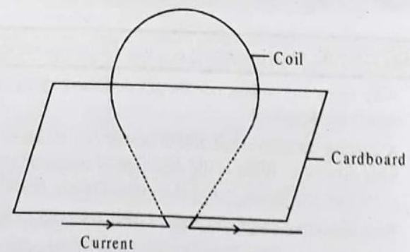
1. What is the nature of magnetic field produced by a straight current carrying conductor? Explain with the help of an experiment.
Show Answer
Answer: The magnetic field produced around a straight current carrying conductor is in the form of concentric circles with the centre lying on the straight conductor.
Take a copper wire AB. Pass it through a cardboard. Connect the wire to a battery through a key. Sprinkle some iron filings on the cardboard. Switch on the key and tap the cardboard gently. You will find that the iron filings arrange themselves in the form of concentric circles. Reverse the direction of current by changing the polarity of the battery. You will find that this time too, the iron filings arrange themselves in concentric circle but in opposite direction. Hence, the magnetic field lines of force around a straight conductor carrying electric current are concentric circles with the conductor at the centre. The direction of magnetic field changes if the direction of current is reversed.
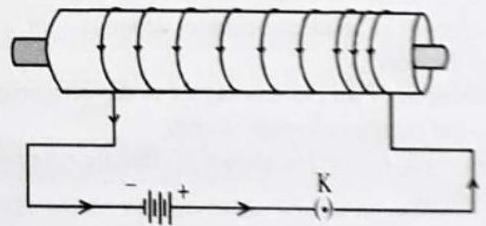
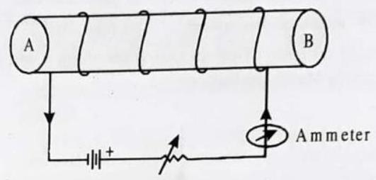
2. Diagram below shows a circuit containing a coil wound over a long and thin hollow carboard tube. Copy the diagram (i) Show the polarity acquired by each face of the solenoid. (ii) Draw the magnetic field lines of force inside the coil and also show their direction. (iii) Mention two methods to increase the strength of the magnetic field inside the coil.
Show Answer
Answer: (i) The polarity acquired by the two ends is as shown below. (A shows North and B shows South polarity
(ii)
(iii) Increase the strength of current, increase the number of turns in the coil, insert soft iron rod in the coil.
3. A 0.4m wire, stretched horizontally, carries an electric current of
(a) the magnitude of the magnetic deflecting force on the wire, and
(b) its direction?
Show Answer
Answer: (a) Given : Length of the wire
Current
Magnetic induction
To calculate : (i) Force
Formula to be used :
Substituting the given values,
(b) By Fleming’s left hand rule, forefinger (magnetic field) points vertically downwards, the middle finger (current) points west and the thumb (force) points towards the south.
4. A straight conductor passes vertically through a cardboard sprinkled with iron filings. Show the setting of the iron filings when a weak current is passed in the downward direction. What changes occur if,
(i) the strength of the current is increased.
(ii) the single conductor is replaced by several parallel conductors with current flowing in the same. direction.
Show Answer
Answer: Figure shows the setting of the iron filings.
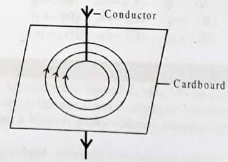
(i) The shape of distribution of iron filings remains unchanged but they get arranged upto a larger distance from the conductor when the strength of current is increased. This is because on increasing the strength of current, the strength of the magnetic field is increased and it is effective upto a larger distance
(ii) Magnetic field strength is increased so the iron filings get arranged upto a larger distance.
5. The diagram shows a current carrying coil passing through a sheet of stiff cardboard. Draw three lines of magnetic field on the cardboard.
Show Answer
Answer: Figure represents the magnetic lines of force due to current carrying coil.
The magnitude of magnetic field at the centre depends on (i) the strength of current in the coil and (ii) the radius of coil.
State two factors on which the magnitude of magnetic field at the centre of coil, depends.
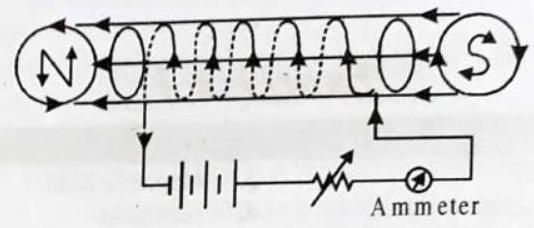
6. Draw a labelled diagram to make an electromagnet from a soft iron bar. Mark the polarity at its ends. What precaution would you observe?
Show Answer
Answer: The labelled diagram is shown in figure.
Precaution : The source of current must be the d.c. source.
2 EXERCISE
Multiple Choice Questians :
DIRECTIONS : This section contains multiple choice questions. Each question has 4 choices (a), (b), (c) and (d) out of which ONLY ONE is correct.
1. Choose the correct option(s).
The magnetic field inside a long straight solenoid-carrying current
(a) is zero.
(b) decreases as we move towards its end.
(c) increases as we move towards its end.
(d) is the same at all points.
Show Answer
Answer: (d)2. A positively-charged particle (alpha-particle) projected towards west is deflected towards north by a magnetic field. The direction of magnetic field is
(a) towards south
(b) towards east
(c) downward
(d) upward
Show Answer
Answer: (d)3. Which of the following correctly describes the magnetic field near a long straight wire?
(a) The field consists of straight lines perpendicular to the wire.
(b) The field consists of straight lines parallel to the wire
(c) The field consists of radial lines originating from the wire.
(d) The field consists of concentric circles centred on the wire.
Show Answer
Answer: (d)4. A magnet is placed vertically on a paper. Then the number of neutral points obtained on the paper is
(a) zero
(b) one
(c) two
(d) three
Show Answer
Answer: (b)5. A small magnet is placed perpendicular to a uniform magnet field. The forces acting on the magnetic will result in
(a) Rotational motion
(b) Translatory motion
(c) No motion at all
(d) Translational and rotational motion both
Show Answer
Answer: (a)6. A charge of
(a)
(c)
(b)
(d) zero
Show Answer
Answer: (a)7. The magnetic field at a point due to a current carrying conductor is directly proportional to the
(a) current flowing through the conductor
(b) Distance from the conductor
(c) Voltage across the conductor
(d) Resistance of the conductor
Show Answer
Answer: (a)8. Which one of the following substances is the magnetic substances?
(a) Mercury
(b) Iron
(c) Gold
(d) Silver
Show Answer
Answer: (b)9. Magnetic lines do not intersect one-another because
(a) they are at a distance
(b) they are in the same direction
(c) they are parallel to another
(d) at the point intersection there will be two direction of the magnetic force which is impossible
Show Answer
Answer: (d)10. Instrument can be shielded from outside magnetic effects by surrounding them with
(a) Rubber shield
(b) Glass shield
(c) Iron shield
(d) Brass shield
Show Answer
Answer: (c)11. The vertical plane which passes through the magnetic axis of a freely suspended magnetic at rest is called
(a) Magnetic meridian
(b) Geographical meridian
(c) North meridian
(d) South meridian
Show Answer
Answer: (a)12. By removing the inducing magnet, the induced magnetism is
(a) Finished after some time
(b) Finished just after
(c) Not finished for a long time
(d) Not charged
Show Answer
Answer: (b)13. The similar magnets of steel are than the magnets of soft iron
(a) stronger
(b) of equal strength
(c) weaker
(d) none of the above
Show Answer
Answer: (c)14. A bar of soft iron is placed flat on the table. A bar magnet is taken and its south pole is placed on one end of the bar of soft iron. The magnet is held almost vertically. The bar is stroked from one end to the other with magnet. On the other end of the bar, magnet is lifted and again placed on the first end and the bar is again stroked. The end of the bar where the magnet is lifted will be
(a) south pole
(b) no pole
(c) south and north both type
(d) north pole
Show Answer
Answer: (d)15. The angle of decilination at a place is the angle
(a) between the vertical plane and the geographical meridian
(b) between the vertical plane and the magnetic meridian
(c) between the geographical meridian and the magnetic meridian
(d) between the geographical meridian and horizontal plane
Show Answer
Answer: (c)16. The magnetism in a magnet is mainly due to
(a) The orbital motion of the electrons
(b) The spin motion of the electrons
(c) The nuclear charge
(d) None of the above
Show Answer
Answer: (b)17. When the north pole of a strong magnet is brought near to the north pole of a weak magnet then they will
(a) Attract each other
(b) repel each other
(c) first attract and then repel
(d) first repel and then attract
Show Answer
Answer: (a)18. A magnet can be demagnetised by
(a) Hammering the magnet
(b) Putting it in the water
(c) Cooling it
(d) Putting in contact with iron
Show Answer
Answer: (a)19. The effective length of the magnet is
(a) the complete length of the magnet
(b) the distance between the two poles of the magnet
(c) the half of the length of the magnet
(d) the square of the length of the magnet
Show Answer
Answer: (b)20. When the bars of bismuth are placed between the magnetic poles they set their length
(a) perpendicular to the lines of force
(b) along the lines of force
(c) neither perpendicular nor along the lines of force
(d) In any direction
Show Answer
Answer: (a)21. Two bars of soft iron exactly same are given. One of them is a magnet. Without using any thing more, how would you find which is a magnet
(a) By bringing two bars near and noting which one is attracting. The attracting one is a magnet
(b) By bringing two bars near and noting which one is repelling. One which repells is an ordinary iron.
(c) By rubbing one bar with the other and noting which becomes magnet. The bar which is magnetised is an ordinary iron
(d) One bar is placed flat horizontal on the table and the other bar is held vertical with its one end on the middle of first bar. If there is attraction between the two, the vertical bar is magnet otherwise ordinary iron.
Show Answer
Answer: (d)22. Magnetic storms are due to
(a) the rotation of the earth
(b) the revolution of the earth
(c) the rainy season
(d) the appearance off sun spots
Show Answer
Answer: (d)23. Which of the following processes will not produce new magnetic poles?
(a) cutting a bar magnet in half
(b) turning on a current in a solenoid
(c) running a current through a straight wire
(d) placing an iron rod in contact with a magnet
Show Answer
Answer: (c)24. Magnetic field lines start
(a) on
(b) on S-poles
(c) on current-carrying wires
(d) Nowhere
Show Answer
Answer: (d)25. The conductivity of a magnetic substance for the lines of force with respect to air is called the
(a) Magnetic induction
(b) magnetic permeability
(c) magnetic flux density
(d) intensity of magnetisation
Show Answer
Answer: (b)26. Magnetic field lines form circles in the space
(a) near a permanent magnet
(b) around a current-carrying wire
(c) inside a solenoid
(d) inside a current-carrying loop
Show Answer
Answer: (b)27. The angle of inclination of the axis of the magnetic needle to the horizontal plane when suspended freely and is at rest is known as
(a) angle of inclination
(b) angle of variation
(c) angle of declination
(d) none of the above
Show Answer
Answer: (a)28. A tesla is equivalent to
(a) newton per coulomb
(b) newton per ampere-meter
(c) ampere per newton
(d) newton per ampere-second
Show Answer
Answer: (b)29. A vertical wire carries a current upward. The magnetic field north of the wire will be directed
(a) upward
(c) westward
(b) eastward
(d) northward
Show Answer
Answer: (c)30. The magnetic flux is expressed in
(a) dynes
(b) Oerested
(c) Gauss
(d) Weber
Show Answer
Answer: (d)31. The magnetic lines of force, inside a current carrying solenoid, are
(a) along the axis and are parallel to each other
(b) perpendicular to the axis and equidistance from each other
(c) circular and they do not intersect each other
(d) circular at the ends but they are parallel to the axis inside the solenoid.
Show Answer
Answer: (a)32. In a moving coil galvanometer, the magnetic pole pieces are made cylindrical and a soft iron core is placed at the centre of the coil to make the magnetic field
(a) strong
(b) strong and radial
(c) uniform
(d) strong and uniform
Show Answer
Answer: (b)33. Which of the following is not true
(a) Induction precedes attraction
(b) We cannot isolate a single pole
(c) We can magnetise an iron ring
(d) A permanent magnet retains its magnetism even when heated on a flame.
Show Answer
Answer: (d)34. Wrist watches are made antimagnetic by shielding their machinery with
(a) plastic sheets
(b) a metal of high conductivity
(c) a magnetic substance of low permeability
(d) a magnetic substance of high permeability
Show Answer
Answer: (d)35. Which of the following statement is not correct?
(a) The dip angle is the angle between the horizontal and earth’s total magnetic field.
(b) Neutral points are obtained where the earth’s magnetic field is perpendicular to that due to a magnet
(c) A magnetic field is a region in which a magnetic force can be detected.
(d) Magnetic fields are vector quantities
Show Answer
Answer: (b)36. When a bar magnet is broken into two pieces?
(a) we will have a single pole on each piece
(b) each piece will have two like poles
(c) each piece will have two unlike poles
(d) each piece will be lose magnetism
Show Answer
Answer: (c)37. The permanent magnets are kept with soft iron pieces at ends as keepers
(a) to magnetise the soft iron pieces
(b) to increase the strength of the magnets
(c) to avoid self demagnetisation
(d) for physical safety of the magnets
Show Answer
Answer: (c)38. A small magnet is placed perpendicular to a constant magnetic field. The forces acting on the magnet will result in
(a) rotation
(b) translation
(c) no motion at all
(d) rotation as well as translation
Show Answer
Answer: (d)39. The vertical component of the earth’s magnetic field is
(a) zero at the magnetic pole
(b) zero at the geographic pole
(c) same everywhere
(d) zero at the magnetic equator
Show Answer
Answer: (d)40. A small piece of a substance gas repelled when it is brought near a powerful magnet. The substance can be
(a) dimagnetic
(b) paramagnetic
(c) ferromagnetic
(d) non-magnetic
Show Answer
Answer: (a)41. Which of the following statement is not correct about two parallel conductors carrying equal currents in the same direction?
(a) Each of the conductors will experience a force
(b) The two conductors will repel each other.
(c) There are concentric lines of force around each conductor
(d) Each of the conductors will move if not prevented from doing so
Show Answer
Answer: (b)42. Which of the following determines the direction of magnetic field due to a current carrying conductor?
(a) Faraday’s laws of electromagnetic induction
(b) Fleming’s left-hand rule
(c) Lenz’s rule
(d) Maxwell’s cork screw rule
Show Answer
Answer: (d)43. Along the direction of current carrying wire, the value of magnetic field is?
(a) Zero
(b) Infinity
(c) Depends on the length of the wire
(d) Uncertain
Show Answer
Answer: (a)44. To obtain maximum intensity of magnetic field at a point the angle between position vector of point and small elements of length of the conductor is
(a) 0
(b)
(c)
(d)
Show Answer
Answer: (c)45. The value of magnetic field due to a small element of current carrying conductor at a distance
(a) zero
(b) maximum
(c) inversely proportional to the current
(d) none of the above
Show Answer
Answer: (b)46. The value of intensity of magnetic field at a point due to a current carrying conductor depends
(a) Only on the value of current
(b) Only on a small part of length of conductor
(c) On angle between the line joining the given point to the mid point of small length and the distance between the small length of the point
(d) On all and the above
Show Answer
Answer: (d)47. An electric current
(a)
(b)
(c)
(d)
Show Answer
Answer: (b)48. In a coaxial, straight cable, the central conductor and the outer conductor carry equal currents in opposite direction. The magnetic field is zero-
(a) outside the cable
(b) inside the inner conductor
(c) inside the outer conductor
(d) in between the two conductors
Show Answer
Answer: (a)49. When the number of turns in a toroidal coil is doubled, the value of magnetic flux density will become
(a) four times
(b) eight times
(c) half
(d) double
Show Answer
Answer: (d)50. By a current carrying toroid, whose area of cross-section is fixed, the magnetic induction produced will be -
(a) maximum at inner end
(b) maximum at outer end
(c) maximum at center of area of cross-section
(d) equal at whole area of cross-section
Show Answer
Answer: (d)51. When an electron beam is moving in a magnetic field, then the work done is equal to the
(a) charge of electron
(b) magnetic field
(c) product of electronic charge and the magnetic field
(d) zero
Show Answer
Answer: (d)52. Which of the following rays are not deflected by a magnetic field -
(a)
(b)
(c)
(d) positive rays
Show Answer
Answer: (c)53. Two parallel beams of electron moving in the same direction will
(a) repel each other
(b) attract each other
(c) not interact with each other
(d) annihilate each other
Show Answer
Answer: (b)54. An inverse square law of distance is obeyed by-
(a) the force per unit length between two long straight parallel current-carrying conductors in vacuum.
(b) the electric field intensity outside an isolated charged sphere
(c) the magnetic flux density outside a long straight current-carrying wire
(d) the electrostatic potential
Show Answer
Answer: (b)55. A current carrying loop lying in a magnetic field behaves like a.
(a) A magnetic dipole
(b) magnetic pole
(c) magnetic material
(d) non-magnetic material
Show Answer
Answer: (a)More Than One Carrect :
DIRECTIONS : This section contains multiple choice questions. Each question has 4 choices
1. Which of the following is/are valid for a current carrying circular coil?
(a) To induce magnetic induction of constant magnitude (at the centre of the coil), current required in it is directly proportional to its radius
(b) Induction of inducted magnetic field at the centre is inversely proportional to the radius of the coil
(c) Induction of the inducted magnetic field at the centre is directly proportional to the current flowing through the directly proportional to the current flowing through the coil
(d) None of the above
Show Answer
Answer: (a,b,c)2. A current flows along the length of a long thin cylindrical shell:
(a) magnetic field at all the points lying inside the shell is zero
(b) magnetic field at any point outside the shell varies inversely with distance from the surface of the shell
(c) magnetic field strength is maximum just outside the shell
(d) none of the above
Show Answer
Answer: (a,c)3. A proton moving with a constant velocity passes through a region of space without any change in its velocity. If
(a)
(b)
(c)
(d)
Show Answer
Answer: (a,d)4. Figure shows a bar magnet and a long straight wire
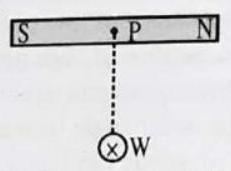
Which of the following statements is/are correct?
(a) If
(b) If
(c) If
(d) None of the above
Show Answer
Answer: (a,b,c)5. A straight conductor carries a current. Assume that all free electrons in the conductor move with the same drift velocity
(a)
(b)
(c)
(d)
Show Answer
Answer: (a,d)6. A charged particle enters into a space and continues to move undeflected. Then in that space:
(a) a uniform horizontal electric field and a vertical magnetic field may be present
(b) a vertical electric field alone may be present
(c) uniform electric and magnetic fields, both directed vertically downwards, may be present
(d) a uniform horizontal magnetic field alone may be
Show Answer
Answer: (b,c,d)7. A long straight conductor, carrying a current
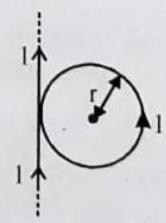
(a) is directed into the paper
(b) is directed out of the paper
(c) has magnitude
(d) has magnitude
Show Answer
Answer: (a,c)8. L is a circular ring made of a uniform wire. Current enters and leaves the ring through straight conductors which, if produced, would have passed through the centre
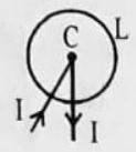
(a) due to the straight conductors is zero
(b) due to the loop is zero
(c) due to the loop is proportional to
(d) due to the loop is proportional to
Show Answer
Answer: (a,b)9. A flat circular coil carrying a current has a magnetic moment
(a)
(b) the direction of
(c) the direction of
(d) the direction of
Show Answer
Answer: (b,c)10. A current carrying ring is placed in a magnetic field. The direction of the field is perpendicular to the plane of the ring:
(a) there is no net force on the ring
(b) the ring will tend to expand
(c) the ring will tend to contract
(d) either (b) or (c) depending on the directions of the current in the ring and the magnetic field
Show Answer
Answer: (a,d)11. A solenoid is connected to a source of constant e.m.f. for a long time. A soft iron piece is inserted into it. Then:
(a) self-inductance of the solenoid gets increased
(b) flux linked with the solenoid increases; hence, steady state current gets decreased
(c) energy stored in the solenoid gets increased
(d) magnetic moment of the solenoid gets increased
Show Answer
Answer: (a,c,d)12. In the loops shown in figure all curved sections are either semicircles or quarter circles. All the loops carry the same current. The magnetic fields at the centres have magnitudes
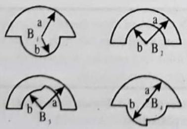
(a)
(c)
(b)
(d)
Show Answer
Answer: (a,b,c)Fill in the Passage :
DIRECTIONS : Fill in the blanks in the following passage(s) from the words given inside the box.
I.
magnet, carrying, magnetic effect, electricity, magnitude of current, deflection increases, eastwards, southwards.
Oersted was the first to put forth the direct relation between ………1…….. and magnetism. He conducted several experiments to determine the ………2…….. of a current ………3…….. wire. The following describes the Oersted experiment conducted to establish that a current carrying wire acts as a ………4…….. .
A long straight wire is connected to an external battery and an electric current is passed through it. When a magnetic needle is placed below the wire such that the wire is parallel to the axis of the magnetic needle and the current flows in the south to north direction, a deflection in the needle is observed. It is observed that the north pole of the needle is deflected westwards and as the ………5…….. is increased, the deflection, ………6…….. till the north pole of the needle turns towards exact west. It is also observed that if instead of placing the magnetic needle below the wire, if it was placed above the wire, the north pole of the magnetic needle is deflected . ………7…….. .
Show Answer
Answer: (1) electricityII.
poles, attracts, east-west, north-south like, opposite, repel, magnetic
A magnet ………1…….. small pieces of iron, nickel, cobalt, etc. The magnetic force of attraction is maximum is small regions near the ends of the magnet. These are called the ………2…….. of the magnet.
A freely suspended magnet always points in ………3…….. direction. The end pointing towards north is called north seeking pole or north pole. The other end which points towards south is called south seeking pole or south pole.
All nagnets attract ………4…….. poles of other magnets and also a few substances like iron, nickel and cobalt. Thus if an unknown substance is attracted by a magnet, we cannot be sure whether it is a magnet. But like poles of magnet ………5…….. each other. Hence if there is repulsion between an unknown substance and a magnet, we can be sure that the unknown substance is a magnet. The substances and a magnet, we can be sure that the unknown substance is a magnet. The substances which are attracted by magnets are called ………6…….. substances.
Show Answer
Answer: (1) attractsIII.
concentric circles, centre, opposite, polarity, straight conductor, reversed, same, circluar conductor.
The magnetic field produced around a straight current carrying conductor is in the form of ………1…….. with the ………2…….. lying on the straight conductor.
Take a copper wire AB. Pass it through a cardboard. Connect the wire to a battery through a key. Sprinkle some iron filings on the cardboard. Switch on the key and tap the cardboard gently. You will find that the iron filings arrange themselves in the form of concentric circles. Reverse the direction of current by changing the ………3…….. of the battery. You will find that this time too, the iron filings arrange themselves in concentric circle but in ………4…….. direction.
Hence, the magnetic field lines of force around a ………5…….. carrying electric current are concentric circles with the conductor at the centre. The direction of magnetic field changes if the direction of current is ………6……..
Show Answer
Answer: (1) Concentric circlesPassage Based Questions :
Passage-I
An electron with kinetic energy
1. The magnetic dipole moment of the electron due to its orbital motion has magnitude :
(a)
(b)
(c)
(d)
Show Answer
Answer: (c)2. The magnetic dipole moment of a positive ion with kinetic energy
(a)
(b)
(c)
(d) Zero
Show Answer
Answer: (b)3. An ionized gas consists of
(a)
(b)
(c)
(d)
Show Answer
Answer: (d)Passage-II
Take a tightly-wound solenoid of radius
1. The magnetic field due to this solenoid at the centre of its axis is
(a)
(b)
(c)
(d)
Show Answer
Answer: (d)2. The magnetic field due to the solenoid at the centre of its axis in the situation
(a)
(b)
(c)
(d)
Show Answer
Answer: (c)3. The magnetic field due to the solenoid at the centre of its axis in the situation
(a) zero
(b)
(c)
(d) infinite
Show Answer
Answer: (c)Passage-III
In a television tube, each of the electrons in the beam has a kinetic energy of
1. The direction in which beam deflects :
(a) east
(b) west
(c) north-eas
(d) south-west
Show Answer
Answer: (a)2. The acceleration of any electron due to the magnetic field is
(a)
(b)
(c)
(d)
Show Answer
Answer: (d)3. The transverse deflection of the beam after travelling 20.0
(a)
(b)
(c)
(d) none of these
Show Answer
Answer: (b)Assertion & Reason :
DIRECTIONS : Each of these questions contains an Assertion followed by reason. Read them carefully and answer the question on the basis of following options. You have to select the one that best describes the two statements.
(a) If both Assertion and Reason are correct and Reason is the correct explanation of Assertion.
(b) If both Assertion and Reason are correct, but Reason is not the correct explanation of Assertion.
(c) If Assertion is correct but Reason is incorrect .
(d) If Assertion is incorrect but Reason is correct .
1. Assertion : A direction current flows through a metallic rod, produced magnetic field only outside the rod.
Reason : There is no flow of charge carriers inside the rod.
Show Answer
Answer: (e) In the case of metallic rod, the charge carries flow through whole of the cross section. Therefore, the magnetic field exists both inside as well as outside. However magnetic field inside the rod will go no decreasing as we go towards the axis.2. Assertion : A proton moves horizontally towards a vertical long conductor having an upward electric current. It will deflect vertically downward.
Reason : Seeing the proton and the conductor from the side of the proton, the magnetic field at the site of the proton will be towards right. Hence the force
Show Answer
Answer: (a)3. Assertion : Force experienced by moving charge will be maximum if direction of velocity of charge is perpendicular to applied magnetic field.
Reason : Force on moving charge is independent of direction of applied magnetic field.
Show Answer
Answer: (c) From equation F = quB sin4. Assertion : A neutral body may experience a net nonzero magnetic force.
Reason : The net charge on a current carrying wire is zero, but it can experience a force in a magnetic field.
Show Answer
Answer: (a)5. Assertion : There is no change in the energy of a charged particle moving in a magnetic field although a magnetic force is acting on it.
Reason : Work done by centripetal force is always zero.
Show Answer
Answer: (a) Magnetic force is always perpendicular to the direction of motion of charged particle, i.e., work done on the charge particle moving on a circular path in magnetic field is zero.6. Assertion : When two long parallel wires, hanging freely are connected in series to a battery, they come closer to each other.
Reason : Wires carrying current in opposite direction repel each other.
Show Answer
Answer: (b) The wires are parallel to each other but the direction of current in it is in same direction so they attract each other. If the current in the wire is in opposite direction then wires repel each other. When the currents are in opposite directions, the magnetic forces are reversed and the wires repels each other7. Assertion : A solenoid tends to expand, when a current passes through it.
Reason : Two straight parallel metallic wires carrying current in same direction attract each other.
Show Answer
Answer: (d) When current flows through a solenoid, the currents in the various turns of the solenoid are parallel and in the same direction. Since the currents flowing through parallel wires in the same direction lead to force of attraction between them, the turns of the solenoid will also attract each other and as a result the solenoid tends to contract.8. Assertion : In a conductor, free electrons keep on moving but no magnetic force acts on a conductor in a magnetic field.
Reason : Force on free electrons due to magnetic field always acts perpendicular to its direction of motion.
Show Answer
Answer: (c) In a conductor, the average velocity of electrons is zero. Hence no current flows through the conductor. Hence, no force acts on this conductor.9. Assertion : A small coil carrying current, in equilibrium, is perpendicular to the direction of the uniform magnetic field.
Reason : Torque is maximum when plane of coil and direction of the magnetic field are parallel to each other.
Show Answer
Answer: (b) The torque acting on a coil is given by,
where
10. Assertion : Basic difference between an electric line and magnetic line of force is that former is discontinuous and the later is continuous or endless.
Reason : No electric lines of force exist inside a charged body but magnetic lines do exist inside a magnet.
Show Answer
Answer: (a) In case of the electric field of an electric dipole, the electric lines of force originate from positive charge and, end at negative charge. Since, isolated magnetic lines are closed continuous loops extending throughout the body of magnet, hence they from endless curves.11. Assertion : No net force acts on a rectangular coil carrying a steady current when suspended freely in a uniform magnetic field.
Reason : Force on coil in magnetic field is always non-zero.
Show Answer
Answer: (c) Force acting on each pair of the opposite sides of the coil are eqMultiple Matching Quesions :
DIRECTIONS : Following question has four statements
1. In column I, the positions of small current carrying loops have been shown and in column II information related to force experienced by coil is given. Match the entries of column I with the entries of column II. (Assume solenoid radius to be small as compared to its length)
| Column-I | Column-II | ||
|---|---|---|---|
| A. |  |
p. | Attractive |
 |
q. | Repulsive | |
 |
r. | Zero | |
 |
s. | Initially zero, then starts Increasing |
Show Answer
Answer:
The force experienced by a coil in a magnetic field is given by
The force comes out to be zero at centre and as we approach it from some outside point, its value increases.
For D: The coil first rotates to allign itself in such a manner so as to link the maximum flux and then the case would be same as that of
2. In magnetic field, for a charged particle, match the entries of column I with the entries of column II.
| Column I | Column II | |||
|---|---|---|---|---|
| A. | Acceleration | p. | may be zero | |
| B. | Velocity | q. | is zero | |
| C. | Speed | r. | may be constant | |
| D. | Kinetic energy | s. | is constant |
Show Answer
Answer:
Work done by magnetic force is zero. From work-energy theorem, its speed or kinetic-energy is constant.
3. A circular current carrying loop is placed in

| Column I | Column II | |||
|---|---|---|---|---|
| A. | Magnetic moment of the loop is | p. | Zero | |
| B. | Torque on the loop is | q. | maximum | |
| C. | Potential energy of the loop is | r. | along |
|
| D. | Equilibrium of the loop is | s. | stable | |
| t. | None |
Show Answer
Answer:
HOTS Subjective Questians :
DIRECTIONS : Answer the following questions.
1. Consider a circular loop of wire lying in the plane of the table. Let the current pass through the loop clockwise. Apply the right-hand rule to find out the direction of the magnetic field inside and outside the loop.
Show Answer
Answer: Direction of magnetic field inside the loop is perpendicular to the plane of paper inward and direction of magnetic field outside the loop is perpendicular to the plane of paper outward.2. When is the force experienced by a current-carrying conductor placed in a magnetic field largest?
Show Answer
Answer: The force experienced by a current-carrying conductor placed in a magnetic field is largest when the direction of current is at right-angles to the direction of the magnetic field.3. Two charged particles are projected into a magnetic field that is perpendicular to their velocities. If the charges are deflected in opposite directions, what does this tell you about the particles?
Show Answer
Answer: Since the charged particles are deflected in opposite directions in the same magnetic field, we can say that they have opposite charges, may be electron and proton, for example.4. A current through a horizontal power line flows in east to west direction. What is the direction of magnetic field at a point directly below it and at a point directly above it ?
Show Answer
Answer: The current is in the east-west direction. Applying the righthand thumb rule, we get that the direction of magnetic field at a point below the wire is from north to south. The direction of magnetic field at a point directly above the wire is from south to north.5. A magnetic field that varies in magnitude from point to point but has a constant direction (east to west) is set up in a chamber. A charged particle enters the chamber and travels undeflected along a straight path with constant speed. What can you say about the initial velocity of the particle?
6. An electron travelling west to east enters a chamber having a uniform electrostatic field in north to south direction Specify the direction in which a uniform magnetic field shoulu be set up to prevent the electron from deflecting from its straight line path.
7. An electron in passing through a field but no forces acting on it. Under what condition it is possible, that the motion of the electron will be in the (i) electric field (ii) magnetic field?
Show Answer
Answer: (i) In electric field, there is always a force on the moving electron opposite to the direction of field. Thus the force will be zero only if field is zero.
(ii) In magnetic field, the force acting on a moving electron is
8. The energy of a charged particle moving in a uniform magnetic field does not change. Explain
Show Answer
Answer: When a charged particle is moving in a uniform magnetic field it experiences a force in a direction, perpendicular to its direction of motion. Due to which the speed of the charged particle remains unchanged and work done on it is zero, hence its kinetic energy remains same.9. A loop of irregular shape carrying current is located in an external magnetic field. If the wire is flexible, why does it change to a circular shape?
Show Answer
Answer: It assumes circular shape with its plane normal to the field to maximize flux, since for a given perimeter, a circle encloses greater area than any other shape.10. An electron does not suffer any deflection while passing through a region. Are you sure that there is no magnetic field? Is the reverse definite?
Show Answer
Answer: If electron passing through a certain region does not suffer any deflection, then we are not sure that there is no magnetic field in that region. This is due to that electron suffers no force when it moves parallel or antiparallel to magnetic field. Thus the magnetic field may exist parallel or antiparallel to the direction of motion of electron.11. Why is pure iron not used for making permanent magnets? Name one materials used for making permanent magnets. Describe how permanent magnets are made electrically. State two examples of electrical instruments made by using permanent magnets.
Show Answer
Answer: Pure iron is not used for making permanent magnets because it cannot retain their magnetism for long time and used only for electromagnet since alloys of iron and steel have strongly magnetised and have a capacity to hold it for a longer time period, they are used for permanent magnets. Material used for permanent magnet-ALNICO. Formation of a permanent magnet electrically. Permanent magnets can be formed by placing a hard steel rod in the strong uniform magnetic field produced by the solenoid. Steels have the quality to retain its magnetism after switch off the solenoid current.
Permanent magnets are used in
(i) Galvanometer
(ii) Ammeter.
12. The flow of a current in a circular loop of wire creates a magnetic field at its centre. How may existence of this field be detected? State the rule which helps to predict the direction of this magnetic field.
Show Answer
Answer: To detect the presence of the magnetic field created by the current in a circular loop at the centre, one can draw the magnetic field lines with the help of compass needle. The magnetic field lines appear as a straight line at the centre and other lines appear in the same direction without the loop. Direction of field is given by the right hand thumb’s rule. Right hand thumb rule. Hold the wire in your right hand with your extended thumb pointing in the direction of current. Your folded fingers will indicate the direction of magnetic field around the wire.13. How does the strength of the magnetic field at the centre of a circular coil of wire depend on :
(i) the radius of the coil
(ii) the number of turns of wire in the coil
(iii) the strength of current flowing in the coil ?
Show Answer
Answer: The strength of the magnetic field produced at the centre of a circular coil of radius
Thus, the strength of a magnetic field in the coil is
(i) inversely proportional to the radius of the loop.
(ii) directly proportional to the number of turns.
(iii) directly proportional to the current passing through it.
14. How will the magnetic field intensity at the centre of a circular coil carrying current change, if the current through the coil is doubled and the radius is halved?


