Chapter 04 Current Electricity
Introduction
When we switch on the bulb of our rooms, it glows immediately. When we connect our room heater to the ‘pins’ placed on the walls, it produces heat. When we provide ‘cells’ to our torch and press its button, it glows and produces light. All of these phenomena are based on the subject matter of this chapter and the next.
Moving charges produce electric current. Electric current produces many effects like heating effect, chemical effect, magnetic effect, etc. This chapter provides us a strong base on how electric current is produced, which instruments are used for electrical measurement, the factors affecting electric current, etc. The chapter also deals with the factor which resists the flow of electric current known as ’electrical resistance’.
ELECTRIC CURRENT
We define the electric current, or simply the current, to be the net amount of charges passing per unit time across any section through a conductor. If the charges are positive, the current is assumed to flow in the direction of charges and if the charges are negative, the current is in a direction opposite to the charges.
If
The
That is,
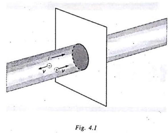
In a conductor such as copper, the current is due to the motion of the negatively charged electrons. Therefore, when we speak of current in an ordinary conductor, such as a copper wire, the direction of the current will be opposite to the direction of flow of electrons.
If the charge on an electron is
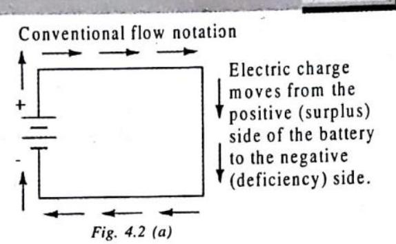
CONVENTIONAL FLOW NOTATION
When Benjamin Franklin made his conjecture regarding the direction of charge flow (from the smooth wax to the rough wool), he set a precedent for electrical notation that exists to this day, despite the fact that we know electrons are the constituent units of charge, and that they are displaced from the wool to the wax – not from the wax to the wool – when those two substances are rubbed together. This is why electrons are said to have a negative charge: because Franklin assumed electric charge moved in the opposite direction that it actually does, and so objects he called “negative” (representing a deficiency of charge) actually have a surplus of electrons.
By the time the true direction of electron flow was discovered, the nomenclature of “positive” and “negative” had already been so well established in the scientific community that no effort was made to change it, although calling electrons “positive” would make more sense in referring to “excess” charge. You see, the terms “positive” and “negative” are human inventions, and as such have no absolute meaning beyond our own conventions of language and scientific description. Franklin could have just as easily referred to a surplus of charge as “black” and a deficiency as “white,” in which case scientists would speak of electrons having a “white” charge (assuming the same incorrect conjecture of charge position between wax and wool).
However, because we tend to associate the word “positive” with “surpius” and “negative” with “deficiency,” the standard label for electron charge does seem backward. Because of this, many engineers decided to retain the old concept of electricity with “positive” referring to a surplus of charge, and label charge flow (current) accordingly. This is known as conventional flow notation.
Others chose to designate charge flow according to the actual motion of electrons in a circuit. This form of symbology is known as electron flow notation:
Electron flow notation
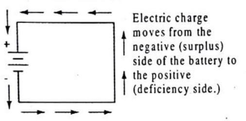
Fig. 4.2 (b)
In conventional flow notation, we show the motion of charge according to the (technically incorrect) labels of + and - . This way the labels make sense, but the direction of charge flow is incorrect. In electron flow notation, we follow the actual motion of electrons in the circuit, but the + and - labels seem backward. Does it matter, really, how we designate charge flow in a circuit? Not really, so long as we’re consistent in the use of our symbols. You may follow an imagined direction of current (conventional flow) or the actual (electron flow) with equal success insofar as circuit analysis is concerned.
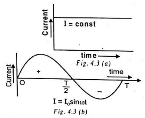
Types of Current
(a) Direct Current : The current whose magnitude and direction does not vary with time is called direct current (dc). The various sources are cells, battery, dc dynamo etc.
(b) Alternating Current : The current whose magnitude continuously changes with time and periodically changes its direction is called alternating current. It has constant amplitude and has alternate positive and negative halves. It is produced by ac dynamo.
When an electric light switch is made an, the light cames on immediately.
The current may be canstituted by mation of different type of charge carviers in different situations.
| S.Na. | Nature of material | Catse of current |
|---|---|---|
| 1. | Conductors | Motion of etectrons |
| 2. | Vacuum tubes | Mation of electrans |
| 3. | Semiconductors | Motion of hotes and electrons |
| 4. | Electrolytes | Mation of pasitue and negative ions |
| 5. | Discharge tube | Motion of pasitive and negative ions |
CHECK Po int
If a current of one-or two-tenths of an ampere were to flow into one of your hands and out the other, you would protably be electrocuted. But, if the same current were to flow into your hand and out the elbow above the same hand, you censld survive, even though the current might be large enough to burn your flesh. Explain.
Show Answer
SOLUTION
If a current of one-or-two-tenths of an ampere flows into one of our hands and out the other, we may be electrocuted, probably, because the electric circuit formed becomes closed. But when the same current flows into the hand and out the elbors above the same hand, the electric circuit is not completed, and we could survive.
ILLUSTRATION-4.1
If a current 3.2 ampere per second flows through a conducting wire, calculate the number of electrons passing through the wire.
Show Answer
SOLUTION:
Here,
ILLUSTRATION-4.2
If 25 coulomb charge flow in a conductor in 5 seconds then find out the value of electric current in it.
Show Answer
SOLUTION:
Electric current
ILLUSTRATION-4.3
If a light bulb uses 0.50 ampere of current, how much charge flows through it in 5 minutes ?
Show Answer
SOLUTION:
Five minute is 300 seconds, so from
RESISTANCE
Directly connecting the poles of a voltage source together with a single piece of wire is dangerous because the magnitude of electric current may be very large in such a short circuit, and the release of energy very dramatic (usually in the form of heat),you may have heard about firing due to short circuit. Usually, electric circuits are constructed in such a way as to make practical use of that released energy, in as safe a manner as possible. One practical and popular use of electric current is for the operation of electric lighting. The simplest form of electric lamp is a tiny metal “filament” inside of a clear glass bulb, which glows white-hot (incandesces) with heat energy when sufficient electric current passes through it. Like the battery, it has two conductive connection points, one for electrons to enter and the other for
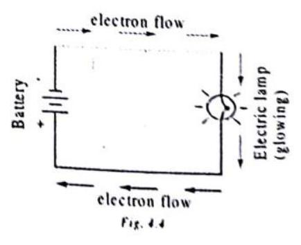 something like this:
As the electrons work their way through the thin metal filament of the lamp, they encounter more opposition to motion than they typically would in a thick piece of wire. This opposition to electric current depends on the type of material, its cross-sectional area, and its temperature. It is technically known as resistance. (It can be said that conductors have low resistance and insulators have very high resistance.) This resistance serves to limit the amount of current through the circuit with a given amount of voltage supplied by the battery, as compared with the “short circuit” where we had nothing but a wire joining one end of the voltage source (battery) to the other.
When electrons move against the opposition of resistance, due to friction heat is generated. Just like mechanical friction, the friction produced by electrons flowing against a resistance manifests itself in the form of heat. The concentrated resistance of a lamp’s filament results in a relatively large amount of heat energy dissipated at that filament. This heat energy is enough to cause the filament to glow white-hot, producing light, whereas the wires connecting the lamp to the battery (which have much lower resistance) hardly even get warm while conducting the same amount of current. How to deal with resistance mathematically? You will find the answer in Ohm’s law section.
Knowledge Enhancer
The reciprocal of resistance is called conductance
Examples silver, copper, mercury, carbon, mica etc.
The substances which do not obey Ohm’s law are called non-ohmic or non linear conductors. The
FACTORS AFFECTING RESISTANCE
The resistance of a conductor depends on temperature, nature of material, length and area of cross-section. If the resistance of the wire at
where
From eq. (1), we have
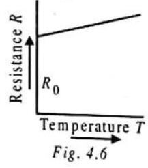
If
Therefore, if the resistance of a wire at
where
Thus, the resistance of a pure metallic wire or the resistivity of a metal is directly proportional to its absolute temperature. The resistivity of alloys also increases with rise in temperature, but this increase is much smaller compared to pure metals. There are certain alloys such as manganin, constantan, nichrome, etc., whose resistivity is little affected by temperature, that is, their temperature coefficient of resistance is negligible. On account of their high resistivity and negligible temperature coefficient of resistance, these alloys are used to make wires for standard resistances, resistance boxes, etc.
170 Current Electricity
COLOUR CODE FOR CARBON RESISTORS
First Colour Code
| Colour | Strip A | Strip B | Strip C | Strip D Tolerance |
|---|---|---|---|---|
| Black | 0 | 0 | ||
| Brown | 1 | 1 | ||
| Red | 2 | 2 | ||
| Orange | 3 | 3 | ||
| Yellow | 4 | 4 | ||
| Green | 5 | 5 | ||
| Blue | 6 | 6 | ||
| Violet | 7 | 7 | ||
| Grey | 8 | 8 | ||
| White | 9 | 9 | ||
| Gold | - | - | ||
| Silver | - | - | ||
| NoColour | - | - | - |
Aid to memory
BBROY of Great Britain has a Very Good Wife.
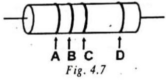
The first two rings give first two significant figures of resistance. The third ring indicates the decimal multiplier i.e. the number of zeros that will follow the two significant figures. The fourth ring shows tolerance or percentage accuracy.
Factors on which the resistance of a conductor depends
The resistance of ohmic circuit elements such as metal wires or carbon resistor depends on their geometries.
To find dependence, first we will keep the thickness of the object (like a copper wire) fixed and just increase or decrease the length of the wire. If we apply a potential difference across the ends of the wire and use current and potential difference measurements, we can determine its resistance as a function of length. We find that there is a proportionality between the length
If instead we fix the length of the copper wire and vary the thickness or crosssectional area A then we find the resistance of the copper decreases as the cross-sectional area A of the wire increases. In fact we get an inverse relation-
ship so that
Combining these two expressions gives us:
To simplify this expression, we can replace the product of the two constants with a single new constant and write
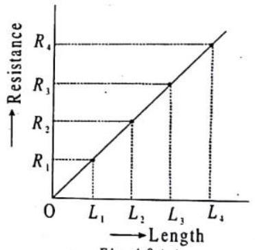
Fig.
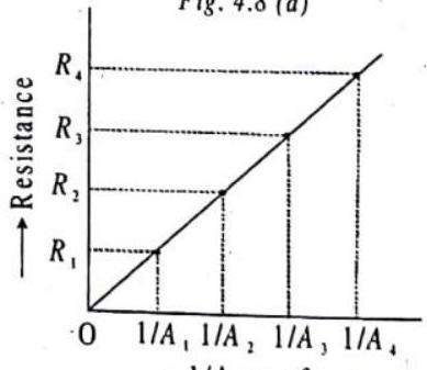
Fig. 4.8 (b)
Where
Definition of resistivity
If
Resistance of some metallic conductors rises with increase in temperature, e.g. copper, silver etc. Resistance of some alloys such as manganin and constantan changes very slowly with increase in temperature. Contrary to this, resistance of semiconductors such as germanium
On decreasing temperature of some metals, the resistance becomes zero at a certain temperature.
For example : Resistance of mercury becomes zero at
Activity
Complete an electric circuit consisting of a cell, an ammeter, a nichrome wire of length
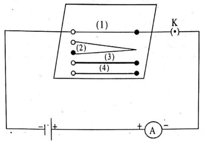
Fig. 4.9 : Electric circuit to study the factors on which the resistance of conducting wires depends.
Now, plug the key. Note the current in the ammeter.
Replace the nichrome wire by another nichrome wire of same thickness but twice the length, that is
Now replace the wire by a thicker nichrome wire, of the same length
Instead of taking a nichrome wire, connect a copper wire [marked (4) in Fig. ] in the circuit. Let the wire be of the same length and same area of cross-section as that of the first nichrome wire [marked (1)]. Note the value of the current.
Notice the difference in the current in all cases.
Does the current depend on the length of the conductor?
Does the current depend on the area of cross-section of the wire used?
Knowledge Enhancer
If a wire is stretched such that length becomes
New cross-sectional arqea
CHECK POINT :
Choose the correct alternative
(a) Alloys of metals usually have (greater/less) resistivity than that of their constituent metals.
(b) Alloys usually have much (lower/higher) temperature coefficients of resistance than puremetals.
(c) The resistance of graphite and most non-metals increases/decreases with increase in temperature.
(d) The resistivity of a semiconductor increases/decreases rapidly with increasing temperature.
(e) The resistivity of the alloy manganin is nearly independent of/increases rapidly with increases of temperature.
(f) The resistivity of a typical insulator (e.g., amber) is greater than that of a metal by a factor of the order of
Show Answer
Solution
(a) Alloys of metals usually have greater resistivity than that of their constituent metals.
(b) Alloys usually have much lower temperature coefficients of resistance than pure metals.
(c) The resistance of graphite and most non metals decreases with increase in temperature.
(d) The resistivity of a semiconductor decreases rapidly with increasing temperature.
(e) The resistivity of the alloy manganin is nearly independent of increasing temperature.
(f) The resistivity of a typical insulator (e.g. amber) is greater than that of a metal by factor of the order of
ILLUSTRATION-4.4
The resistivity of copper at room temperature is
Show Answer
SOLUTION:
ILLUSTRATION-4.5
The resistance of a wire of length
Show Answer
SOLUTION:
Sp. resistance
ILLUSTRATION-4.6
What length of resistance wire of resistivity
Show Answer
SOLUTION:
ILLUSTRATION-4.7
Two wires
Show Answer
SOLUTION:
Let
Resistance of the wire
where
But
ILLUSTRATION-4.8
Calculate the resistance of
Show Answer
SOLUTION:
Given
Resistivity
ELECTRIC CIRCUIT
To learn more on electricity we need to draw electric circuits with elements like batteries (combination of cells), bulbs, wire, switches, ammeter, voltmeter, Rheostat etc.
1. Cell
Direct current source of electromotive force.
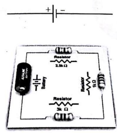
Fig. 4.10 : Simple circuit showing battery and resistor.
2. Rheostat (variable resistance)
Wire of special type of alloy like manganin, eureka, nichrome etc. is wound on a hollow cylinder of china clay. It controls the current in the electric circuit.

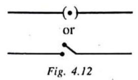
3. Switch
It is used to close or open the electric circuit, controls the movement of electrons in a circuit.
4. Ammeter
Determines the value of current flowing in the circuit. The resistance of ammeter is small and it is used in series with the circuit.

5. Voltmeter
Determines the potential difference between two points in the circuit. Its resistance is high and it is used in parallel with the resistance wire.

CHECK POINT :
One example of a water system is a garden hose that waters a garden. Another is the cooling system of an automobile. Which of these exhibits behavior more analogous to that of an electric circuit? Why?
Show Answer
SOLUTION:
The garden hose is more analogous to an electric circuit as it contains a source of water in which there is a pressure difference like an electric circuit contains a source of electrical energy which has a potential difference. Also, the water is supplied through a pipe in the same way as a conducting path is provided for the flow of electrical energy in a circuit.
OHM’s LAW
According to Ohm’s law ‘The current passing through a conductor is directly proportional to the potential difference between its ends, provided the physical conditions of conductor remain unchanged.”
where
Unit of resistance
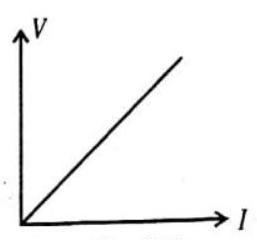
Fig. 4.15
The unit of resistance is ohm
If
The resistance of a conductor is 1 ohm if a potential difference of 1 volt is produced across its ends when 1 ampere of the current flows through it.
The conductors, which obey the Ohm’s law are called the ohmic conductors or linear resistances. All metallic conductors (such as silver, aluminium, copper, iron, etc.) are the ohmic conductors.
The conductors, which do not obey the Ohm’s law are called the non-ohmic conductors or non-linear resistances. Examples are, diode valve, triode valve, transistors, electrolyte, etc.
It is sometime contended that
Activity
Take a nichrome wire, a torch bulb, a
Set up the circuit by connecting four dry cells of

Complete the circuit by connecting the nichrome wire in the gap XY. Plug the key. Note down the ammeter reading. Take out the key from the plug. Always take out the key from the plug after measuring the current through the circuit.
Replace the nichrome. wire with the torch bulb in the circuit and find the current through it by measuring the reading of the ammeter.
Now repeat the above step, with the
Are the ammeter readings differ for different components connected in the gap
You may repeat this Activity by keeping any material component in the gap. Observe the ammeter readings in each case. Analyse the observations.
VERIFICATION OF OHM’s LAW
Set up a circuit as shown in figure with a battery switch
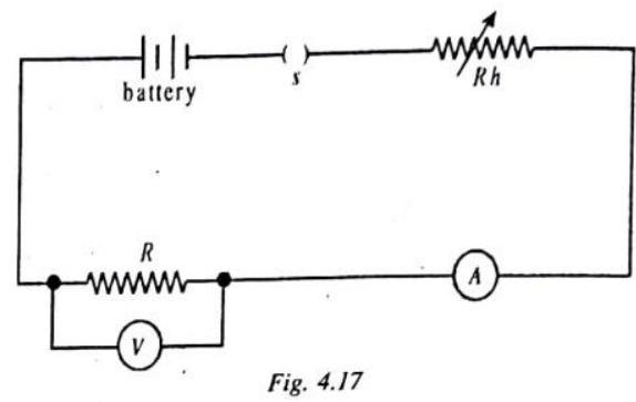
Tabulate your results as shown below :
| Trial No. | Potential difference |
Current I (ampere) | |
|---|---|---|---|
| 1. | |||
| 2. | |||
| 3. |
Plot a graph of
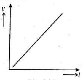
Fig. 4.18
Limitation of Ohm’s Law
1. Ohm’s law does not apply to conductors such as diode, radio valves, metal rectifiers, electricity through gases.
2. Ohm’s law is applicable only when the physical conditions remain constant, for example the resistance of some conductors will vary if the wires are heated or placed under tension.
3. Ohm’s law is applicable only when the temperature of the conductor is constant. Generally the resistance of pure metals increases with temperature but the resistance of certain other conducting materials like carbon decreases with temperature. There are certain metal alloys of magnesium and copper whose resistance changes with temperature.
CHECK POINT :
Is Ohm’s law universally applicable for all conducting elements? If not, give examples of elements which do not obey Ohm’s law.
Show Answer
SOLUTION:
Ohm’s law is not a fundamental law in nature. It is not universally followed semiconductor diodes, Transistor, Thermistors, vacuum tubes do not follow ohm’s law.
ILLUSTRATION- 4.9
Calculate the potential difference required across ’ a conductor of resistance
Show Answer
SOLUTION:
Given
From Ohm’s, law,
ILLUSTRATION- 4.10
How much electric current is produced on applying potential difference of 30 volts on a wire of resistance
Show Answer
SOLUTION:
ILLUSTRATION-4.11
If ampere current flowing through a resistance wire develops a potential difference of 50 volts across its ends, find the resistance of the resistance wire.
Show Answer
SOLUTION:
ILLUSTRATION-4.12
The potential difference between the terminals of an electric heater is
Show Answer
SOLUTION:
We are given, potential difference
According to Ohm’s law,
When the potential difference is increased to
The current through the heater becomes
ILLUSTRATION- 4.13
A relay with a resistance of 12 ohms is in an electric circuit with one side at a potential of 85 volts and the other at 71 volts. How much current is in the relay?
Show Answer
SOLUTION:
The potential difference across the relay is
COMBINATION OF RESISTORS
In many practical applications to have desired value of resistance two or more resistances are required to be combined. This can be done in two ways : (i) In series and (ii) In parallel. Sometimes resistances are to be combined in such a way that some resistances be in series and some in parallel. Such a combination is called mixed grouping.
If, in an electrical circuit, two or more resistances connected between two points are replaced by a single resistance such that there is no change in the current of the circuit and in the potential difference between those two points, then the single resistance is called the ’equivalent resistance’.
When the resistance of a circuit is to be increased, they are combined in series and when heavy current is to be passed, they are combined in parallel so as to decrease the total resistance.
SERIES COMBINATION
In this combination, the resistances are joined end to end. Thus the second end of each resistance is joined to the first end of the next resistance, and so on. The first end of the first resistance and the second end of the last resistance are connected to the cell. In this combination, the same current flows in all the resistances but the potential differences between their ends are different according to their resistances.
In figure, three resistances
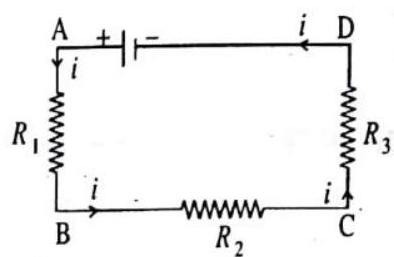
Fig. 4.19
Suppose a current is flowing in all the three resistances. Suppose the potential differendes between the ends of the resistances
If the potential difference between points
The equivalent resistance between points
Comparing eq. (1) and (2), we get
That is, the equivalent resistance of the resistances connected in series is equal to the sum of those resistances and is thus greater than any individual resistance.
Activity
Join three resistors of different values in series. Connect them with a battery, an ammeter and a plug key, as shown in Fig. You may
se the resistors of values like
Plug the key. Note the ammeter reading.
Change the position of ammeter to anywhere in between the resistors. Note the ammeter reading each time.
Do you find any change in the value of current through the ammeter ?

Activity
In previous Activity, insert a voltmeter across the ends
Plug the key in the circuit and note the voltmeter reading. It gives the potential difference across the series combination of
resistors. Let it be
Take out the plug key and disconnect the voltmeter. Now, insert the voltmeter across the ends
Plug the key and measure the potential difference across the first resistor. Let it be
Similarly, measure the potential difference across the other two resistors, separately. Let these values be
Deduce a relationship between

PARALLEL COMBINATION
When two or more resistances are combined in such a way that their first ends are connected to one point and the second ends to another point then this combination is in parallel. resistances is same but the current in different resistances are different.
In Fig. 4.22, three resistances
Let the potential difference between the points
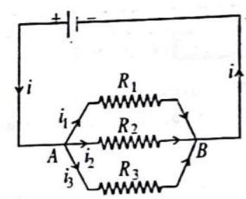
Fig. 4.22
Substituting these values in eq. (1) we get,
If the equivalent resistance between the points
Comparing eq. (2) and (3), we get
That is, the reciprocal of the equivalent resistance of the resistances connected in parallel is equal to the sum of the reciprocals of those resistances.
In parallel combination, the equivalent resistance
If resistance
Solving eq. (1) and (2)
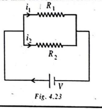
Activity:
Make a parallel combination,

Take out the plug from the key. Remove the ammeter and voltmeter from the circuit. Insert the ammeter in series with the resistor
CHECK POINT :
Given
Show Answer
SOLUTION:
(i) For maximum effective resistance, all the resistors should be joined in series.
(ii) For minimum effective resistance all the resistors should be joined in parallel
So
Now,
ILLUSTRATION-4.14
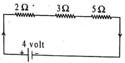
Three resistances of 2,3 and 5 ohms are connected in series. If the combination is connected to a battery of 4 volt then what will be (i) current in each resistance (ii) potential difference across each resistance?
Show Answer
SOLUTION:
Total resistance in series
(i) Current flowing through each resistance will be same
(ii) Potential difference across each resistance will be
determined by formula
Potential difference across
Potential difference across
Potential difference across
ILLUSTRATION-4.15
Three resistors of
Show Answer
SOLUTION:
Given
(i) In series, the equivalent resistance is
(ii) In parallel, the equivalent resistance is
ILLUSTRATION-4.16
Two resistors of
Show Answer
SOLUTION:
The circuit diagram is shown in figure.
(i) If resistance of the combination is
or
Let current through the battery be
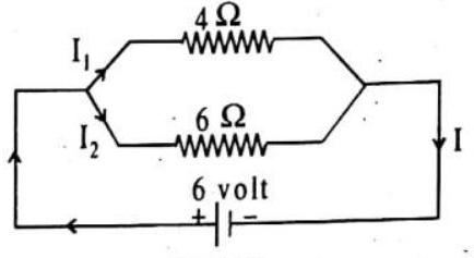
Fig. 4.26
(ii) The potential difference across each resistor is
Current through
Current through
ILLUSTRATION-4.17
(a) the combined resistance
(b) the potential difference across the combined resistor
(c) the current through the
Show Answer
SOLUTION:
Find the combined resistance
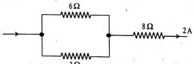
The equivalent circuit is shown in Fig. 4.27 (b).

(a) Let the combined resistance of all three resistors be
Fig. 4.27 (b)
(b) Let the potential difference across the combined resistors be
(c) The combined resistance of the parallel network is
For the
ILLUSTRATION-4.18
Three resistors are connected in series to 24 volt battery, and an ammeter in the circuit reads 0.50 amperes. The first resistor is rated at
Show Answer
SOLUTION:
(a) The total resistance of the circuit is
(b) In a series circuit, resistance add, so
(c) For any circuit element,
ILLUSTRATION-4.19
In the circuit shown, find :
(a) the equivalent resistance between points
(b) the current through the battery.
Show Answer
SOLUTION:
Given:
Find: (a)
(b)
(a) The three resistors are in a parallel combination.
So,
Or using
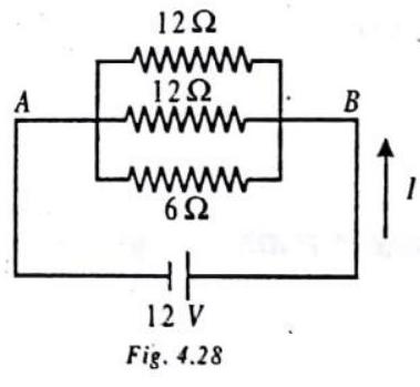
Now the two
(b) From Ohm’s law,
ELECTRICAL MEASURING INSTRUMENTS
Galvanometer
A galvanometer is an instrument which is used to measure current or voltage, as per requirement.
Ammeter
An ammeter is a low resistance galvanometer used to measure strength of current in an electrical circuit.
An ammeter is always connected in series in a circuit because when an ammeter is connected in series it does not appreciably change the resistance of circuit and hence the main current flowing through the circuit. An ideal ammeter has zero resistance. The reading of an ammeter is always less than actual current in the circuit because all practical ammeters have low finite resistance.
Smaller is the resistance of an ammeter more accurate will be the reading.
A galvanometer can be converted to an ammeter by connecting a low resistance shunt in parallel to coil of galvanometer.
Here
Here
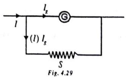
Shunt (S)
Current Electricity
It is a low resistance connected in parallel to coil of galvanometer to convert it to ammeter. It protects a galvanometer from strong currents. It is also used to alter range of an ammeter.
The resistance of converted ammeter is
The range of an ammeter is increased by reducing shunt resistance
If
The range of an ammeter can be increased
It is possible to increase the range of an ammeter because it lowers the resistance of ammeter further.
The length of the shunt required
Reducing the shunt resistance may increase range but it reduces the sensitivity.
Voltmeter
A voltmeter is a high resistance galvanometer used to measure potential difference.
A voltmeter is connected in parallel to a circuit element because when connected in parallel it draws least current from the main current. So it measures nearly accurate potential difference.
An ideal voltmeter has infinite resistance.
The reading of a voltmeter is always less than actual value because all practical voltmeter may have large but finite resistance. Greater is the resistance of voltmeter more accurate is its reading.
A galvanometer can be converted to a voltmeter by connecting a high resistance in series with coil of galvanometer.
The resistance of converted voltmeter is
The range of a voltmeter is increased by increasing the series resistance.
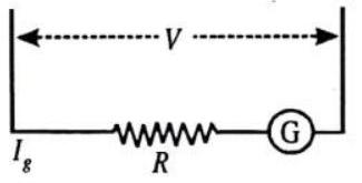
Fig. 4.30
The value of resistance required to increase range
KIRCHHOFF’S LAW
This law is used to solve a problem regarding electrical circuit. The law has two parts.
(a) Kirchhoff’s first law or current law or junction rule
In any electrical network, the algebraic sum of currents meeting at a junction is always zero i.e.
The sum of currents flowing towards a junction is equal to sum of currents
leaving the junction.
By convention the current directed towards the junction is positive while those directed away from the junction is taken as negative.
The first law is in accordance with conservation of charge.
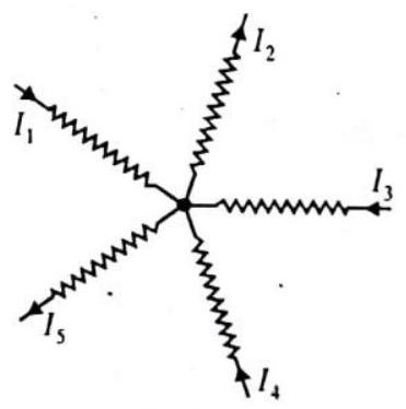
Fig. 4.31
The charges do not accumulate at a junction. The total charge entering a junction is equal to total charge leaving the junction.
(b) Kirchhoff’s second law or voltage law or loop rule
The algebraic sum of all the potential drops and emf’s along any closed path in a network is zero. i.e.
The second law is in accordance with conservation of energy.
According to second law, the electric energy given to the charge by a source of emf is lost in passing through resistance. The change in potential in covering a resistance in the direction of current is negative (-IR) while in opposite direction it is positive.

The potential falls along direction of current. The potential fall is taken as negative while potential rise is taken as positive.
The emf of source is taken as positive when it is traversed from negative to positive terminal while it is taken as negative when it is traversed from positive to negative irrespective of the direction of current.

If there are
ILLUSTRATION-4.20
Determine the current through the dc source in the following network:
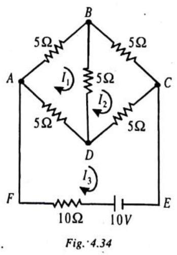
Show Answer
SOLUTION:
We assume the loop, or mush, currents
Solving the equations, (1) and (2), we get
Then, substituting these values of
ILLUSTRATION-4.21
Calculate the current in each resistance in the given circuit.
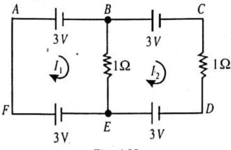
Fig. 4.35
Show Answer
SOLUTION:
Let us assume the loop currents
The current in the resistance of
Knowledge Enhancer
Wheatstone Bridge
It is an arrangement of four resistances devised by Charles Wheatstone which is used to measure an unknown resistance.
The Wheatstone bridge principle states that if four resistances
In balanced condition
The condition of balance depends on resistance
In state of balance the cell and galvanometer can be interchanged.
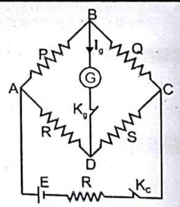
Fig. 4.36 While performing an experiment at start press the cell key
The resistance of balanced Wheatstone bridge between
In unbalanced bridge
If
If
METER BRIDGE
The metre bridge, shown, is a practical arrangement of the Wheatstone’s bridge. It consists of a
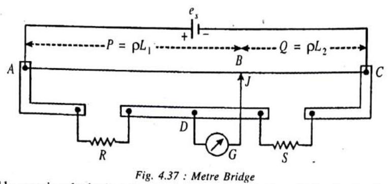 A null situation is obtained by moving the jockey
 where
ILLUSTRATION-4.22
If the current through the branch
Find the resistance
Show Answer
SOLUTION:
The given circuit, when rearranged, is found to be a
Wheastone’s bridge circuit, as shown.
Since, the current through the branch
The branch
Further, this resistance is connected in series with the resistance of
Then, the current through the resistance
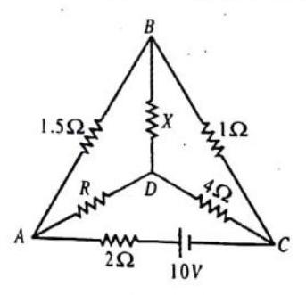
Fig. 4.38
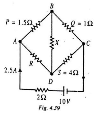
ILLUSTRATION-4.23
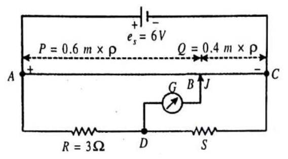
A metre bridge circuit is shown in the balanced state. The bridge wire
Show Answer
SOLUTION:
From the balance condition, we have
The equivalent resistance between
Then, the current drawn from the dc source is
MISCELLANEOUS SOLVED EXAMPLES
1. If
Show Answer
SOLUTION:
Given
The charge in
So,
2. In the circuit shown, find : (a) the equivalent resistance between points
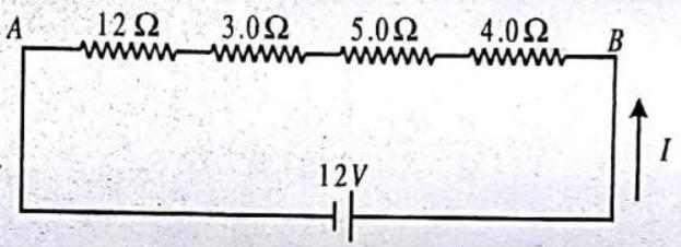
Show Answer
SOLUTION:
Given :
(a) All four resistors are in series combination, so
(b) The current through all resistors in series is the same
3. For the combination of resistors shown in figure, find the equivalent resistance between (i)

Show Answer
SOLUTION:
(i) The resistors
The resistance
Thus the equivalent resistance between
4. Two copper wires
Show Answer
SOLUTION:
From the relation
Resistance of wire
Resistance of wire
On dividing
Thus the wire
5. How much energy is given to each coulomb of charge passing through a
Show Answer
SOLUTION:
Energy
6. (a) How much current will an electric bulb draw from a
(b) How much current will an electric heater coil draw from a
Show Answer
SOLUTION:
(a) We are given
From Eq.
(b) We are given,
From Eq.
The difference of current drawn by an electric bulb and electric heater from the same
7. Resistance of a metal wire of length
Show Answer
SOLUTION:
We are given the resistance
Therefore, from the resistivity of the given metallic wire is
Substitution of values in this gives
The resistivity of the metal at
8. An electric lamp of
Show Answer
SOLUTION:
toaster
Total current drawn
Current to be drawn by iron
Resistance of electric iron
9. What is (a) the highest, (b) the lowest total resistance that can be secured by combinations of four coils of resistance
Show Answer
SOLUTION:
(a) Highest - By connecting the resistors in series. So
(b) Lowest - By connecting the resistors in parallel.
So,
10. How many
Show Answer
SOLUTION:
When
Current drawn from cell
11. A nichrome wire has a resistance of
Show Answer
SOLUTION:
Case
Case
Dividing (2) by (1)
12. Calculate the equivalent resistance between points
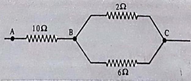
Show Answer
SOLUTION:
Resistance of
Now, equivalent resistance
13. Three resistors of
Show Answer
SOLUTION:
Resistance of
(i)
(ii) P.D. across
P.D. across
P.D. across
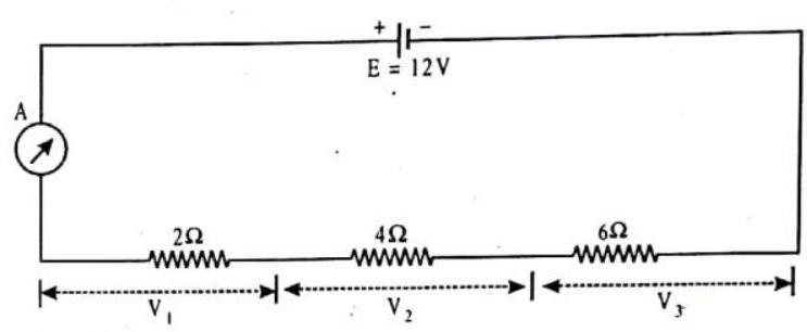
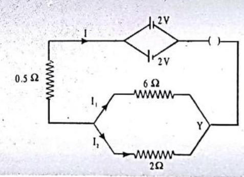
14. Two cells of
(i) total resistance of the circuit.
(ii) current flowing through
(iii) current flowing through
Show Answer
SOLUTION:
EMF of the battery
Effective resistance of the parallel resistors is given by
Total resistance of the circuit,
Main current
(ii) Current flowing through
P.D. across the junctions :
(iii) Hence, current
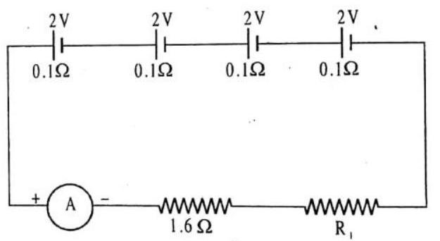
15. Four cells each of emf
Show Answer
SOLUTION:
The circuit diagram is shown in figure.
(i) Total internal resistance
(ii) Total emf
(iii) Current in circuit
(iv) Potential difference across
1 EXERCISE
Fill In The Blanks
DIRECTIONS : Complete the following statements with an appropriate word / term to be filled in the blank space(s).
1. The colour coding of wires is ………….. for earth ………….. for live and ………….. for neutral.
Show Answer
Answer: Green, red, black2. The rate of flow of electric charge is called …………..
Show Answer
Answer: current3. Current is measured with an instrument called a (an). …………..
Show Answer
Answer: ammeter4. If there is no current, a voltmeter connected across a resistor will register. ………….. voltage.
Show Answer
Answer: zero5. Between any two points in a circuit, the sum of all ………….. is the same through any pathway.
Show Answer
Answer: potential difference6. Combined resistance is the sum of separate resistances provided that the various conductors are connected in …………..
Show Answer
Answer: series7. In a parallel circuit, each circuit element has the same…………..
Show Answer
Answer: potential difference8. Copper is a preferred material for making wire because of its low. …………..
Show Answer
Answer: resistivity9. The SI unit of electric current is …………..
Show Answer
Answer: ampere10. ………….. is a property that resists the flow of electrons in a conductor.
Show Answer
Answer: Resistance11. The SI unit of resistance is …………..
Show Answer
Answer: ohm (2)12. The potential difference across the ends of a resistor is
………….. to the current through it, provided its ………….. remains the same.
Show Answer
Answer: directly proportional, temperature13. The resistance of a conductor depends directly on its
………….. inversely on its ………….. , and also on the ………….. of the conductor.
Show Answer
Answer: length, area of cross-section, material14. The slope of voltage (along
Show Answer
Answer: resistance15. An ammeter should have very, ………….. resistance.
Show Answer
Answer: low16. Current is measured by an instrument called, …………..
Show Answer
Answer: ammeter17. The phenomenon of losing of electrical resistance by a conductor on cooling it to an extremely low temperature is known as …………..
Show Answer
Answer: superconductivityTrue / False:
DIRECTIONS : Read the following statements and write your answer as true or false.
1. A copper wire of length
Show Answer
Answer: True2. The drift velocity of electrons in a metallic wire will decrease if the temperature of the wire is increased.
Show Answer
Answer: True3. Two wires, each of radius
Show Answer
Answer: False4. The drift velocity of an electron is doubled if the applied electric field across the conductor is doubled.
Show Answer
Answer: True5. The temperature coefficient of resistance of a wire is
Show Answer
Answer: False6. The quantity of charge flowing past a point multiplied by time is a current.
Show Answer
Answer: False7. The resistivity of all pure metals increases with the rise in temperature.
Show Answer
Answer: True8. Ohm’s law is a relation between the power used in a circuit to the current and the potential difference.
Show Answer
Answer: False9. Direction of current is taken opposite to the direction of flow of electrons.
Show Answer
Answer: True10. A cell generates a potential difference across its terminals
Show Answer
Answer: True11. The equivalent resistance of several resistors in series is equal to the sum of their individual resistances.
Show Answer
Answer: True12. In parallel combination, the reciprocal of equivalent resistance is the sum of the reciprocal of individual resistance.
Show Answer
Answer: True13. A voltmeter is always connected in series in the circuit to measure the potential difference between two points.
Show Answer
Answer: False14. The resistivity of an alloy is generally lower than that of pure metals which form the alloy.
Show Answer
Answer: False15. The series arrangement is used for domestic circuits.
Show Answer
Answer: FalseMatch the following
DIRECTIONS : Each question contains statements given in two columns which have to be matched. Statements
1.
Show Answer
Answer: (a)2. In the figure shown, the value of each resistance is R. match the entries of column I with the entries of column II.
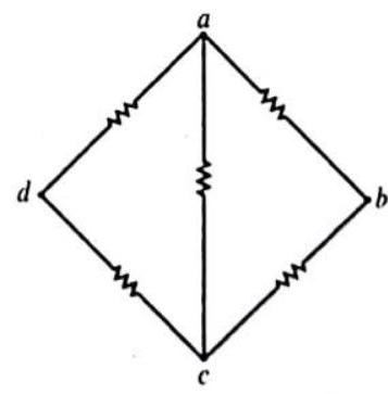
Show Answer
Answer: (a)3. Column II gives order of resistivity for materials in column I Column I
Show Answer
Answer: (a)Very Short Answer Questions:
DIRECTIONS : Give answer in one word or one sentence.
1. What are the factors on which resistance depends?
2. Which combination have maximum value of equivalent resistance?
3. If one coulomb charge flows in a circuit for one second then what will be the value of current in the circuit.
4. Define one ohm resistance.
5. Name the instrument used to measure electric current.
Show Answer
Answer: Ammeter6. Write the unit of electrical resistance.
Show Answer
Answer: Ohm7. Name the best conductor of electricity.
Show Answer
Answer: Silver8. In domestic wiring do we connect various distribution circuits in series?
Show Answer
Answer: No, various distribution circuits are connected in parallel.9. Why is an ammeter likely to be burnt out if you connect it in parallel?
Show Answer
Answer: If an ammeter is connected in parallel, the resultant resistance of the circuit decreases and more current passes through the instrument. Hence, the ammeter is likely to be burnt out.10. What is the resistance of an air gap?
Show Answer
Answer: It is very-very large, say almost infinity.11. Manganin is used for making standard resistors. Why?
Show Answer
Answer: Manganin is an alloy whose temperature coefficient of resistance is almost negligible. So its resistance does not change with change in temperature, that is why it is used in making standard resistors.12. A wire of resistivity
Show Answer
Answer: Resistivity will not change as it depends on the material not on the length.13. A copper wire of resistivity
Show Answer
Answer: Resistivity will not change as it depends on the material not on the diamater of the wire.14. Why is a voltmeter always connected in parallel with a circuit element across which voltage is to be measured?
Show Answer
Answer: Voltage is measured across any two points of a conductor by a voltmeter connected in parallel because potential difference across parallel combination of elements remains same.15. Which physical quantity does the voltage vs current graph for a metallic conductor depict?
Show Answer
Answer: Slope of voltage vs. current graph gives resistance of a metallic conductor. S.I. unit is ohm.16. A carbon resistor of
Show Answer
Answer:17. Specific resistance of copper, silver and constant an are
Show Answer
Answer: The specific resistance of silver is least. So it is the best conductor as the conductivity is the reciprocal of specific resistance.18. Sketch a graph showing variation of resistivity of carbon with temperature.
Show Answer
Answer: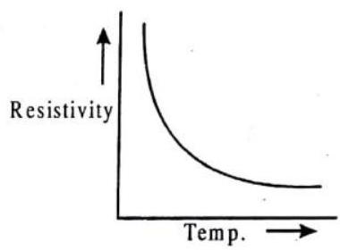
19. Is a current-carrying wire electrically charged?
Show Answer
Answer: A current carrying wire consists of equal number of electrons and protons. Therefore, the wire is not electrically charged.20. A wire has the non-uniform cross-sectional area. A steady current flows through the wire in the direction of increasing cross-sectional area. How does the drift speed of charge carrier change?
Show Answer
Answer:
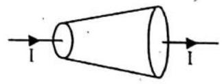
i.e, as the area of cross-section of wire increases in the direction of current
21. V-I graph for a metallic wire at two different temperatures
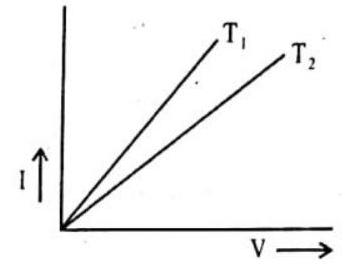
Show Answer
Answer: Resistance increases with increase in temperature. Resistance of metallic wire is the inverse of slope of the graph22. What is the effect on current through a circuit of steady resistance when both voltage and resistance are doubled?
Show Answer
Answer: If both voltage and resistance are doubled, there will be no change in the current.23. Which has the greater electrical resistance, wet skin or dry skin?
Show Answer
Answer: Dry skin has greater resistance than wet skin. There is usually a layer of salt remaining on our skin from respiration. When the skin is wet the salt lowers its resistance.24. What is the source of electrons that makes a shock when you touch a charged conductor?
Show Answer
Answer: The source of electrons that makes a shock when we touch a charged conductor is our body itself.25. A carbon resistor is marked in coloured bands of red, black, organge and silver. What is the resistance and tolerance value of the resistor?
Show Answer
Answer: Red -2 , Black -0 , Orange -3 , SilverShort Answer Questions:
DIRECTIONS : Give answer in 2-3 sentences.
1. Write Ohm’s law. Explain it by giving diagram of an electric circuit.
2. Write the expression for the equivalent resistance
3. Define the term current and state its SI unit.
4. Define the term resistance.
5. A lamp draws a current of
Show Answer
Answer:
6. Join three resistances of
Show Answer
Answer: Two resistance in parallel, and the third in series with them.7. Judge the equivalent resistance when the following are connected in parallel (a)
Show Answer
Answer: (a) When a number of resistances are connected in parallel then their combined resistance is less than the smallest individual resistance. Therefore, equivalent resistance will be less than 1 .
(b) In this case, also the equivalent resistance will be less than 1 .
8. Resistance of a metal wire of length
Show Answer
Answer: We are given the resistance
The resistivity of the metal at
9. The equivalent resistance of circuit diagram is
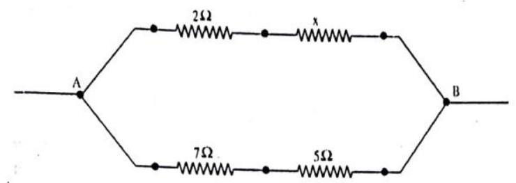
Show Answer
Answer: Equivalent resistance of circuit
Equivalent resistance of
Equivalent resistance of
As
Putting value of
10. The
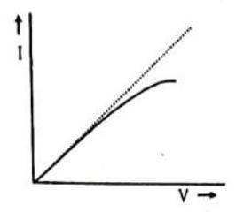
Show Answer
Answer: For higher current there are higher heat or energy losses as11. A potential difference
Show Answer
Answer:12. Why do electrons, rather than protons, make up the flow of charge in a metal wire?
Show Answer
Answer: In conductors, one or more electrons from each atom are free to move throughout the atomic lattice. The movement of electrons produce electric current in the conductor. Protons, on the other hand, are bound to the nuclei of atoms that are more or less locked in a fixed positions. Therefore, protons can’t move and hence can’t contribute to the current.13. Does electric charge flow across a circuit or through a circuit? Does voltage flow across a circuit or is it impressed across a circuit? Explain.
Show Answer
Answer: Electric charges flow through a circuit just like the molecules of water flow through a pipe if there is a pressure difference between its ends.
On the other hand, voltage doesn’t flow across a circuit but it is just impressed across a circuit. Voltage doesn’t go anywhere in a circuit just like pressure doesn’t go through the pipe in the example above.
14. Two resistors of
Show Answer
Answer:15. The equivalent resistance between the point
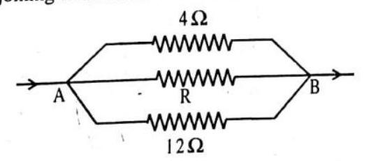
Show Answer
Answer:Long Answer Questions:
DIRECTIONS : Give answer in four to five sentences.
1. How does the resistance of a metallic wire depend on its temperature? Explain the reason to your answer.
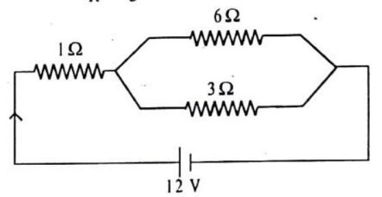
2. A circuit consists of a
Show Answer
Answer: Effective resistance in the parallel circuit is
Total resistances
Current
3. A copper wire has diameter
Show Answer
Answer:4. Three resistors of
Show Answer
Answer: 1.5 ampere, 30 volts, 45 volts.5. When a potential difference of 2 volt is applied across the ends of a wire of
(i) the resistance per unit length of the wire
(ii) the resistance of
(iii) the resistance across the ends of the wire it is doubled on itself.
Show Answer
Answer: (i)6. How can three resistors of resistance
Show Answer
Answer: (a) As the total resistance (equivalent resistance) is
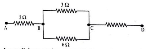
In parallel connection, the equivalent resistance
So, the resistors have to be in a mixed combination. Let us consider the combination show in the figure,
The equivalent resistance between
parallel)
The resistance between
So, the combination shown in the ligure is true.
7. A battery of
Show Answer
Answer: Resistors are connected in series.
So, equivalent resistance
Potential difference,
Current, through the circuit,
8. What is drift velocity of electrons and relaxation time of free electrons in a metallic conductor carrying a current? Establish a relation between them?
Show Answer
Answer: Drift velocity is defined as the average velocity with which the free electrons get drilled towards the positive end of the conductor under the influence of an external electric ficld.
Relaxation time is the average time that has elapsed since each electron suffered its last collision with the atoms or ions of conductor.

Consider a metalic conductor of length
magnitude of electric field,
Since the charge on electron is
If
electron is,
Due to this acceleration, apart from its thermal velocity, acquires additional velocity component in a direction opposite to the direction of electric field. At any instant of time, the velocity acquired by electron having thermal
velocity
Where
Putting the value of
9. Define resistivity of material. Staie its S.I. units and discuss its variation with temperature in case of (i) metals (ii) semiconductors and (iii) insulators.
Show Answer
Answer: The resistivity of the material of a conductor is defined as the resistance of unit length and unit area of cross-section of the conductor. The S.I. unit of resistivity is ohm metre
Resistivity of a material,
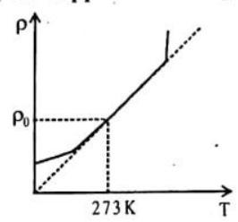
The variation of resistivity with temperature is different in different materials. (a) For metallic conductors
The temperature dependence of resistivity of a metal is given by the relation,
Where
The resistivity of a conductor increases with increase in temperature since
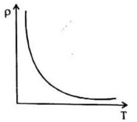
(b) For Semiconductors
For Semiconductors, the resistivity decreases as temperature increases since the value of
(c) For insulators
The resistivity increases exponentially with decrease in temperature. It becomes infinitely large at temperatures near absolute zero.
10. Explain the various types of grouping of cells and find the condition for the maximum current in the external resistor connected to the combination of cells (i) in series (ii) in parallel and (iii) in mixed grouping.
Show Answer
Answer: (a) When cells are arranged in series
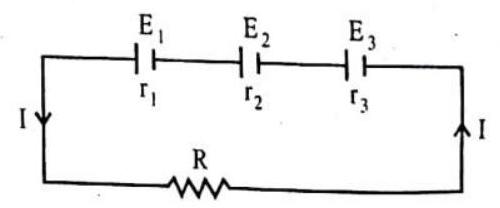
Consider three cells of e.m.f
The equivalent internal resistance of this combination is
If
(b) When cells are arranged in parallel
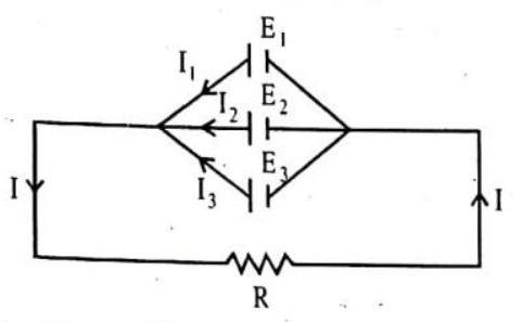
In this combination of cells, the total current is the sum of the currents due to individual cells. Total emf of this combination is the same
The equivalent internal resistance
If
(c) When the cells are in mixed grouping
If there be
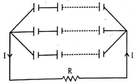
Total resistance in the circuit
Total emf of all the cells
2 EXERCISE
Multiple Choice Questions:
DIRECTIONS : This section contains multiple choice questions. Each question has 4 choices (a), (b), (c) and (d) out of which ONLY ONE is correct.
1. A cylindrical rod is reformed to twice its length with no change in its volume. If the resistance of the rod was
(a)
(b)
(c)
(d)
Show Answer
Answer: (c)2. What is the current through a
(a) zero
(b)
(c)
(d)
Show Answer
Answer: (c)3. A wire carries a steady current of
(a)
(b)
(c)
(d)
Show Answer
Answer: (b)4. The length of a wire is doubled and the radius is doubled. By what factor does the resistance change
(a) 4 times as large
(b) twice as large
(c) unchanged
(d) half as large
Show Answer
Answer: (d)5. A circular conductor is made of a uniform wire of resistance
(a)
(c)
(b)
(d)
Show Answer
Answer: (c)6. A
(a)
(b)
(c)
(d)
Show Answer
Answer: (b)7. Three resistances of 2,3 and
(a)
(b)
(c)
(d)
Show Answer
Answer: (d)8. Two unequal resistances are connected in parallel. Which of the following statement is true
(a) current in same in both
(b) current is larger in higher resistance
(c) voltage-drop is same across both
(d) voltage-drop is lower in lower resistance
Show Answer
Answer: (c)9. You are given
(a)
(b)
(c)
(d)
Show Answer
Answer: (b)10. A piece of wire of resistance
(a)
(b)
(c) 5
(d) 25
Show Answer
Answer: (d)11. 2 ampere current is flowing through a conductor from a 10 volt emf source then resistance of conductor is
(a)
(b)
(c)
(d)
Show Answer
Answer: (b)12. Charge on an electron is
(a)
(b)
(c)
(d)
Show Answer
Answer: (d)13. 20 coulomb charge is flowing in 0.5 second from a point in an electric circuit then value of electric current in amperes will be
(a) 10
(b) 40
(c) 0.005
(d) 0.05
Show Answer
Answer: (b)14. Three resistors of
(a)
(b)
(c)
(d)
Show Answer
Answer: (c)15. A letter ’
(a)
(b)
(c)
(d)
Show Answer
Answer: (c)16. A wire of resistance
(a)
(b)
(c)
(d)
Show Answer
Answer: (a)17. According to international convention of colour coding in a wire
(a) live is red, neutral is black and earth is green
(b) live is red, neutral is green and earth is black
(c) live is brown, neutral is blue and earth is black
(d) live is red, neutral is black and earth is green
Show Answer
Answer: (d)18. If a wire is stretched to make its length three times, its resistance will become
(a) three times
(b) one-third
(c) nine times
(d) one-ninth
Show Answer
Answer: (c)19. The resistivity of a wire depends on
(a) length
(b) area of cross-section
(c) material
(d) all the above three factors
Show Answer
Answer: (c)20. Ampere-second stands for the unit of
(a) power
(c) e.m.f.
(b) charge
(d) energy
Show Answer
Answer: (d)21. In the circuits shown below the ammeter
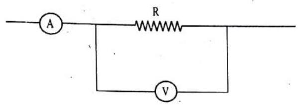
(a) slightly more than 5 ohms
(b) slightly less than 5 ohms
(c) exactly 5 ohms
(d) None of the above
Show Answer
Answer: (a)22. Three resistors are connected to form the sides of a triangle
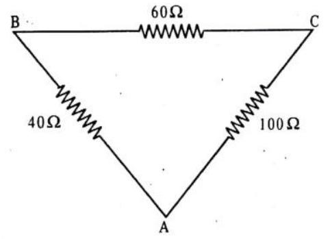
The resistance of side
(a) 50
(b) 64
(c) 32
(d) 100
Show Answer
Answer: (c)23. If one micro-amp. current is flowing in a wire, the number of electrons which pass from one end of the wire to the other end in one second is
(a)
(c)
(b)
(d)
Show Answer
Answer: (a)24. The unit for specific resistance is
(a) ohm
(b) ohm
(c) ohm
(d)
Show Answer
Answer: (b)25. If the temperature of a conductor is increased, its resistance will
(a) not increase
(b) increase
(c) decrease
(d) change according to the whether
Show Answer
Answer: (b)26. The unit for electric conductivity is
(a) ohm per cm
(b) ohm
(c) ohm per second
(d) mho
Show Answer
Answer: (c)27. Two wires of resistance
(a)
(b)
(c)
(d)
Show Answer
Answer: (a)28. Gases are good conductors of electricity at
(a) high pressure
(b) low pressure
(c) low temperature
(d) high temperature
Show Answer
Answer: (b)29. The resistance of a thin wire in comparison of a thick wire of the same material
(a) is low
(b) is equal
(c) depends upon the metal of the wire
(d) is high
Show Answer
Answer: (d)30. If the specific resistance of a wire of length
(a)
(b)
(c)
(d)
Show Answer
Answer: (c)31. If a charge of
(a)
(c)
(b)
(d)
Show Answer
Answer: (c)32. The number of electrons flowing per second through any cross section of wire; if it carries a current of one ampere, will be
(a)
(c)
(b)
(d)
Show Answer
Answer: (b)33. The number of electron passing through a heater wire in one minute, if it carries a current of 8 ampere, will be
(a)
(c)
(b)
(d)
Show Answer
Answer: (d)34. The total momentum of electrons in a straight wire of length
(a)
(c)
(b)
(d)
Show Answer
Answer: (a)35. In a wire of length
(a)
(b)
(c)
(d) none of the above
Show Answer
Answer: (a)36. The resistance between two rectangular faces of a block of dimensions
(a)
(b)
(c)
(d)
Show Answer
Answer: (a)37. If resistance of a wire formed by
(a)
(b)
(c)
(d)
Show Answer
Answer: (a)38. A given piece of wire length
(a)
(b)
(c)
(d) Remains unchanged
Show Answer
Answer: (b)39. A given piece of wire of length
(a)
(b)
(c)
(d)
Show Answer
Answer: (d)40. There are two wires of the same length and of the same material and radial
(a)
(b)
(c)
(d)
Show Answer
Answer: (b)41. Specific resistance of a wire depends on the
(a) length of the wire
(b) area of cross-section of the wire
(c) resistance of the wire
(d) material of the wire
Show Answer
Answer: (d)42. The resistance of some substances become zero at very low temperature, then these substances are called
(a) good conductors
(b) super conductors
(c) bad conductors
(d) semi conductors
Show Answer
Answer: (b)43. The resistance of wire is
(a)
(b)
(c)
(d)
Show Answer
Answer: (d)44. When the resistance of copper wire is
(a)
(b)
(c)
(d)
Show Answer
Answer: (b)45. When the resistance wire is passed through a die the crosssection area decreases by
(a)
(b)
(c)
(d)
Show Answer
Answer: (d)46. Two wires of the same material having lengths in the ratio of
(a)
(b)
(c)
(d)
Show Answer
Answer: (c)47. The resistance
(a) 0
(b)
(c)
(d)
Show Answer
Answer: (b)48. Resistance
(a)
(b)
(c) 0
(d)
Show Answer
Answer: (b)49. The equivalent resistance between points

(a)
(b)
(c)
(d)
Show Answer
Answer: (b)50. The equivalent resistance between points
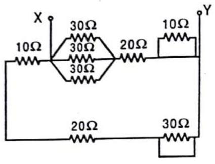
(a)
(b)
(c)
(d)
Show Answer
Answer: (c)51. The equivalent resistance between points
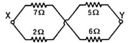
(a)
(b)
(c)
(d)
Show Answer
Answer: (b)52. Three resistances
(a)
(b)
(c)
(d)
Show Answer
Answer:
53. Two wires of same metal have the same length but their cross-sections area in the ratio
(a)
(b)
(c)
(d)
Show Answer
Answer: (a) Same metal means same sip. resistance
54. A certain piece of silver of given mass is to be made like a wire. Which of the following combination of length
(a) L and A
(b)
(c)
(d) Any of the above, because volume of silver remains same
Show Answer
Answer: (c)55. A certain wire has a resistance
(a)
(c)
(b)
(d)
Show Answer
Answer: (b)56. What length of the wire of specific resistance
(a)
(c)
(b)
(d)
Show Answer
Answer: (d)57. The resistance of an ideal voltmeter is
(a) zero
(c) very large
(b) very low
(d) Infinite
Show Answer
Answer: (c) Ideal voltmeter should not draw any current flow source hence its resistance
Practically
58. Masses of 3 wires of same metal are in the ratio
(a)
(c)
(b)
(d)
Show Answer
Answer: (d)
59. When a
(a)
(c) 3 ohm
(b)
(d)
Show Answer
Answer: (c)60. In a Wheatstone’s bridge all the four arms have equal resistance
(a)
(b)
(c)
(d)
Show Answer
Answer: 
As Wheatstone bridge is in balanced condition potential difference across
61. We have two wires
(a)
(b)
(c)
(d) None of the above
Show Answer
Answer: (c) Same material
62. The electric resistance of a certain wire of iron is
(a) The resistance will be doubled and the specific resistance will be halved
(b) The resistance will be halved and the specific resistance will remain unchanged
(c) The resistance will be halved and the specific resistance will be doubled
(d) The resistance and the specific resistance, will both remain unchanged
Show Answer
Answer:
Specific resistance will remain same as it is a material property but remember it depends on temperature.
63. When a wire of uniform cross-section
(a)
(b)
(c)
(d)
Show Answer
Answer: (a) Two resistance (64. A solenoid is at potential difference
(a)
(b)
(c)
(d)
Show Answer
Answer: (a)65. The resistance of a discharge tube is
(a) Ohmic
(b) Non-ohmic
(c) Both
(a) and
(d) Zero
Show Answer
Answer: (b)66. Conductivity increases in the order of
(a)
(b)
(c)
(d)
Show Answer
Answer: (b) Silver is the best conductor of electricity.67. By increasing the temperature, the specific resistance of a conductor and a semiconductor
(a) Increases for both
(b) Decreases for both
(c) Increases, decreases
(d) Decreases, increases
Show Answer
Answer: (c)68. A strip of copper and another of germanium are cooled from. room temperature to
(a) Each of these increases
(b) Each of these decreases
(c) Copper strip increases and that of germanium decreases
(d) Copper strip decreases and that of germanium increases
Show Answer
Answer: (d) Copper is a conductor while germanium is a semiconductor. Resistance of temperature decreases with temperature while that of semi-conductor increases hence resistance of copper strip decreases and that of germanium increases.69. In the circuit shown in the figure, the current through
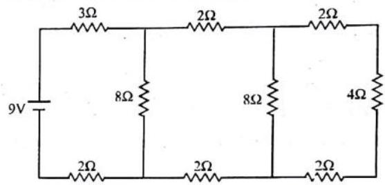
(a) the
(b) the
(c) the
(d) the
Show Answer
Answer: (d)
Passing through
70. Which of the following has a negative temperature coefficient?
(a)
(b)
(c)
(d)
Show Answer
Answer: (a)More than One Correct:
DIRECTIONS: This section contains multiple choice questions. Each question has 4 choices (a), (b), (c) and (d) out of which ONE OR MORE may be correct.
1. A current passes through a wire of non-uniform crosssection. Which of the following quantities are independent cross-section?
(a) The charge crossing in a given time interval
(b) Drift speed
(c) Current density
(d) Free-electron density
Show Answer
Answer: (a,d)2. Two conductors made of the same material have lengths
(a) The potential difference across the two conductors is the same
(b) The electron drift velocity is larger in the conductor of
length
(c) The electric field in the first conductor is twice than that in the second
(d) The electric field in the second conductor is twice than that in the first
Show Answer
Answer: (a,b,c)3. When a potential difference is applied across the ends of a linear-metallic conductor:
(a) the free electrons are set in motion from their position of rest
(b) the free electrons are accelerated continuously from the lower potential end to the higher potential end of the conductor
(c) the free electrons are accelerated continuously from the higher potential end to the lower potential end of the conductor
(d) the free electrons acquire a constant drift velocity from the lower potential end to the higher potential end of the conductor
(e) the vibrating atomic ions in the conductor start vibrating more vigorously
Show Answer
Answer: (d,e)4. Electric current arises from the flow of charged particles. Now:
(a) in metals it is dominant due to flow of electrons
(b) in semiconductors it is jointly due to flow of holes and electrons
(c) in electrolytes it is due to flow of negative ions only
(d) in discharge tubes containing gases at low pressure it is due to flow of positive ions only
Show Answer
Answer: (a,d)5. The potential difference between the points

(a) the current through the
(b) the current through the
(c) the current through the
(d) the potential difference between the terminals of the
Show Answer
Answer: (a,c,d)6. Electric current is due to flow of charge carriers in the conductors. Which of the following is/are correct?
(a) The drift speed of charge carriers is a very small fraction of the mean thermal agitation speed of the same charge carriers
(b) The number of charge carriers per unit volume is always the same as the number of atoms of the conductor per unit volume
(c) The drift velocity is proportional to the electric field applied ordinarily
(d) In an intrinsic semiconductor, the charge carriers are either electrons only or holes only; both of them may not participate in conduction
Show Answer
Answer: (a,c)7. When some potential difference is maintained between
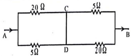
(a) the equivalent resistance between
(b)
(c) no current flows between
(d) current (3//5) flows from
Show Answer
Answer: (a,b,d)

As
8. In the given circuit:
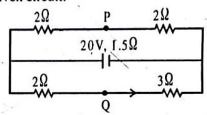
(a) the current through the battery is
(b)
(c)
(d)
Show Answer
Answer: (a,d)9. Three voltmeters, all having different resistances, are joined as shown in the figure. When some potential difference is applied across
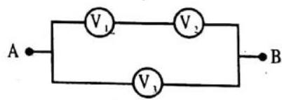
(a)
(b)
(c)
(d)
Show Answer
Answer: (b,c)10. In the circuit, the battery is ideal. A voltmeter of resistance
(a)
(b)
(c)
(d)
Show Answer
Answer: (b, c) Treat all voltmeters and ammeters as resistances. Draw the circuit and find the currents and potential differences for each section.11. Three ammeters
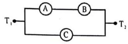
(a)
(b)
(c)
(d)
Show Answer
Answer: (a,b,d)Fill in the Passage.
DIRECTIONS : Complete the following passage(s) with an appropriate word/term to be filled in the blank spaces.
I.
resistance
low potential
Conductors conduct electricity owing to the presence of a large number of …… 1….. When a potential difference is applied across a conductor these electrons begin to drift from the end at …… 2…… to the end at …… 3……. While drifting they collide with other electrons as well as fixed …… 4…… . The fixed ions are formed from the atoms which given free electrons. Thus, even as conductor conducts electricity, at the same time it offers some …… 5……. to the flow of charges.
The obstruction offered by a …… 6….. to the flow of electric current is called its …… 7…….
Show Answer
Answer:
- free electrons
2 . low potential
-
high potential
-
positive ions
-
obstructions
6 . conductor
- resistance
II.
The electric current is defined as the …………… of charge for …………… that crosses the ………….., in much the same sense that a river current is the amount of water ………….. per unit time. When physical conditions remaining same, then the electric current flowing through a ………………. is …………… proportional to the ……………… across the two ends of the conductor.
Show Answer
Answer: 1. amount
- unit time
3 . surface
-
flowing
-
conductor,
-
directly
-
potential difference.
III.
Starting point
In a series combination of resistors, the ……………. of one resistor is connected to the …………… of second resistor. Then the effective resistance of the combination is equal to the …………… of the resistances of …………… resistors. If
Thus, the net resistance of the combination obtained is greater than the largest value of resistance in the combination. In this type of combination, the potential difference across the combination of resistors is divided among the resistors according to the values of their ……..7……. Hence, the resistors in this type of combination act as dividers of ……………. .
Show Answer
Answer:
- end point,
- starting point,
- sum difference,
- individual
- series
- resistances
- potential difference,
Passage Based Questions:
DIRECTIONS : Study the given paragraph(s) and answer the following questions.
Passage -I
Answer the following questions based on the given circuit.
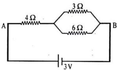
1. The potential drop across the
(a)
(b)
(c)
(d)
Show Answer
Answer: (a) Equivalent resistance of2. The equivalent between points
(a)
(b)
(c)
(d)
3. The current flowing through in the given circuit is
(a)
(b)
(c)
(d)
Passage-II
Answer the following questions based on the given circuit.
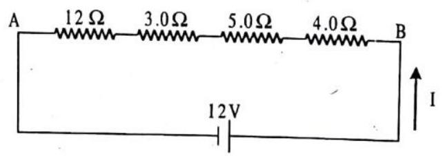
1. The equivalent resistance between points
(a)
(b)
(c)
(d)
2. The current through each resistor is
(a)
(b)
(c)
(d)
3. The potential drop across the
(a)
(b)
(c)
(d)
Passage-III
Answer the following questions based on the given circuit.
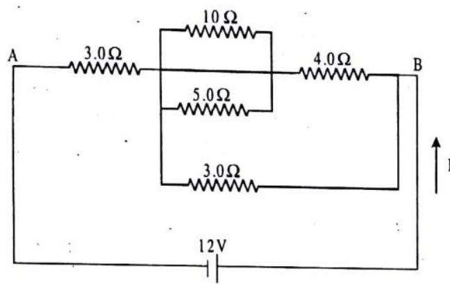
1. The equivalent resistance between points
(a)
(b)
(c)
(d)
2. The current through the battery is
(a)
(b)
(c)
(d)
3. The current through the
(a)
(b)
(c)
(d)
Passage -IV
Answer the following questions based on the given circuit.
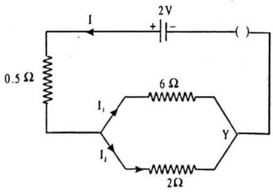
1. The total resistance of the circuit is
(a)
(b)
(c)
(d)
2. The current flowing through
(a)
(b)
(c)
(d)
3. The current flowing through
(a)
(b)
(c).
(d)
Assertion & Reason:
DIRECTIONS : Each of these questions contains an Assertion followed by reason. Read them carefully and answer the question on the basis of following options. You have to select the one that best describes the two statements.
(a) If both Assertion and Reason are correct and Reason is the correct explanation of Assertion.
(b) If both Assertion and Reason are correct, but Reason is not the correct explanation of Assertion.
(c) If Assertion is correct but Reason is incorrect.
(d) If Assertion is incorrect but Reason is correct.
1. Assertion : When a battery is short-circuited, the terminal voltage is zero.
Reason : In the situation of a short-circuit, the current is zero
2. Assertion : The equation
Reason :
3. Assertion : All electric devices shown in the circuit are ideal: The reading of each of ammeter (a) and voltmeter (V) is zero.
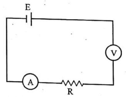
Reason : An ideal voltmeter draws almost no current due to very large resistance, and hence
4. Assertion : If
Reason : The resistance
5. Assertion : The product of resistivity and conductivity of a conductor depends on the material of the conductor. Reason : Because each of resistivity and conductivity depends on the material of the conductor.
6. Assertion : Insulators do not allow flow of current through themselves.
Reason : They have no free-charge carriers.
7. Assertion : Positive charge inside the cell always goes from positive terminal to the negative terminal.
Reason : Positive charge inside the cell may go from negative terminal to the positive terminal.
8. Assertion : Wire
Reason : Resistivity of wire
9. Assertion : Resistivity of material may change with temperature.
Reason : Resistivity is a material property & independent on temperature.
Multiple Matching Questions:
DIRECTIONS : Following question has four statements
1.
| Column I | Column II |
|---|---|
| (A) Ohm’s Law | (p) Direct proportional to area |
| (B) Resistivity | (q) Voltage |
| (C) For Ohmic-conductor | (r) |
| (D) Electric current | (s) |
2.
| Column I | Column II | |
|---|---|---|
| (A) |  |
(p) |
| (B) |  |
(q) |
| (C) | Resistance | (r) |
| (D) |  |
(s) |
3.
| Column I | Column II |
|---|---|
| (A) Ohm | (p) 1 Volt/ 1 Amp |
| (B) Current | (q) Depends on matter of conductor |
| (C) Resistivity | (r) |
| (D) Super conductor | (s) |
HOTS Subjective Questions:
1. In the circuit shown, if a wire is connected between points A and B. How much current will flow through that wire?
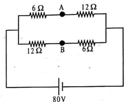
2. A potential difference
(i)
(ii)
(iii)
Justify your answer in each case.
3. What is the number of electrons that would flow per second through the cross-section of a wire when 1 A current flows in it?
4.
5. A current of
6. Name a metal which offers higher resistance to the passage of electricity other than copper.
7. Define the term resistivity of a material.
8. Calculate the resistance of a conductor, if the current flowing through it is
9. A cylinder of a material is
10. Two wires, one of manganin and the other of copper have equal lengths and resistances. Which one of these wires will be thicker?
11. A student obtains resistances


