Modern Physics 6 Question 3

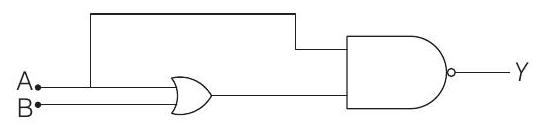
3. The truth table for the circuit given in the figure is

(Main 2019, 12 April I)

(a) $\left|\begin{array}{lll}A & B & Y \ 0 & 0 & 1 \ 0 & 1 & 1 \ 1 & 0 & 1 \ 1 & 1 & 1\end{array}\right|$

(c) $\left|\begin{array}{lll}A & B & Y \ 0 & 0 & 1 \ 0 & 1 & 1 \ 1 & 0 & 0 \ 1 & 1 & 0\end{array}\right|$

(b) $\left|\begin{array}{lll}A & B & Y \ 0 & 0 & 1 \ 0 & 1 & 0 \ 1 & 0 & 0 \ 1 & 1 & 0\end{array}\right|$

(d) $\left|\begin{array}{lll}A & B & Y \ 0 & 0 & 0 \ 0 & 1 & 0 \ 1 & 0 & 1 \ 1 & 1 & 1\end{array}\right|$

Show Answer

Solution:

  1. Given circuit is

Let the intermediate state $X$ of OR gate is shown in figure.

Clearly, $Y=\overline{A X}$

Here, $X=A+B$

$\therefore \quad Y=\overline{A(A+B)}=\overline{A A+A B}$

$$ \begin{aligned} & =\overline{A+A B} \\ & =\overline{A(1+B)} \end{aligned} $$

$$ (\because A A=A) $$

$\Rightarrow \quad Y=\bar{A}$

$(\because 1+B=1)$

So, truth table shown in option (c) is correct.

Alternate Solution We can solve it using truth table

$\boldsymbol{A}$ $\boldsymbol{B}$ $\boldsymbol{X}=\boldsymbol{A}+\boldsymbol{B}$ $\boldsymbol{Y}=\overline{\boldsymbol{A} \boldsymbol{X}}$
0 0 0 1
0 1 1 1
1 0 1 0
1 1 1 0


जेईई के लिए मॉक टेस्ट

एनसीईआरटी अध्याय वीडियो समाधान

दोहरा फलक