Electrostatics 5 Question 4

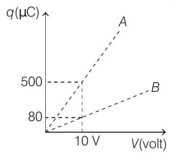
4. Figure shows charge (q) versus voltage (V) graph for series and parallel combination of two given capacitors. The capacitances are

(Main 2019, 10 April I)

(a) 60μF and 40μF

(b) 50μF and 30μF

(c) 20μF and 30μF

(d) 40μF and 10μF

5 The parallel combination of two air filled parallel plate capacitors of capacitance C and nC is connected to a battery of voltage, V. When the capacitors are fully charged, the battery is removed and after that a dielectric material of dielectric constant K is placed between the two plates of the first capacitor. The new potential difference of the combined system is

(a) (n+1)V(K+n)

(b) nVK+n

(c) V

(d) VK+n

(Main 2019, 9 April II)

Show Answer

Answer:

Correct Answer: 4. (b)

Solution:

  1. In the given figure,

Slope of OA> Slope of OB

Since, we know that, net capacitance of parallel combination > net capacitance of series combination

Parallel combination’s capacitance,

CP=C1+C2=500μC10V=50μF

Series combination’s capacitance,

CS=C1C2C1+C2=80μC10V=8μF

or

C1C2=8×(C1+C2)=8×50μF=400μF [using Eq. (i)] 

From Eqs. (i) and (iii), we get

C1=50C2 and C1C2=400C2(50C2)=40050C2C22=400 or C2250C2+400=0C2=+50±250016002=+50±302

C2=+40μF or +10μF

Also, C1=50C2C1=+10μF or +40μF

Hence, capacitance of two given capacitors is 10μF and 40μF.


जेईई के लिए मॉक टेस्ट

एनसीईआरटी अध्याय वीडियो समाधान

दोहरा फलक