Electromagnetic Induction and Alternating Current 2 Question 9

10. A metal $\operatorname{rod} O A$ and mass $m$ and length $r$ kept rotating with a constant angular speed $\omega$ in a vertical plane about horizontal axis at the end $O$. The free end $A$ is arranged to slide

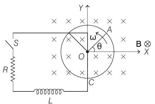
without friction along a fixed conducting circular ring in the same plane as that of rotation. A uniform and constant magnetic induction $\mathbf{B}$ is applied perpendicular and into the plane of rotation as shown in figure. An inductor $L$ and an external resistance $R$ are connected through a switch $S$ between the point $O$ and a point $C$ on the ring to form an electrical circuit. Neglect the resistance of the ring and the rod. Initially, the switch is open.

$(1995,10 M)$

(a) What is the induced emf across the terminals of the switch?

(b) The switch $S$ is closed at time $t=0$.

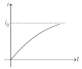
(i) Obtain an expression for the current as a function of time.

(ii) In the steady state, obtain the time dependence of the torque required to maintain the constant angular speed. Given that the $\operatorname{rod} O A$ was along the positive $x$-axis at $t=0$.

Show Answer

Answer:

Correct Answer: 10. (a) $e=\frac{B \omega r^{2}}{2}$

(b) (i) $i=\frac{B \omega r^{2}}{2 R} 1-e^{-\frac{R}{L} t}$ (ii) $\tau _{\text {net }}=\frac{B^{2} \omega r^{4}}{4 R}+\frac{m g r}{2} \cos \omega t$

Solution:

  1. (a) Consider a small element of length $d x$ of the $\operatorname{rod} O A$ situated at a distance $x$ from $O$.

Speed of this element, $v=x \omega$

Therefore, induced emf developed across this element in uniform magnetic field $B$

$$ d e=(B)(x \boldsymbol{\omega}) d x $$

$$ (\because e=B v l) $$

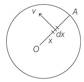
Hence, total induced emf across $O A$,

$$ e=\int _{x=0}^{x=r} d e=\int _0^{r} B \omega x d x=\frac{B \omega r^{2}}{2} \Rightarrow e=\frac{B \omega r^{2}}{2} $$

(b) (i) A constant emf or PD, $e=\frac{B \omega r^{2}}{2}$ is induced across $O$ and $A$.

The equivalent circuit can be drawn as shown in the figure.
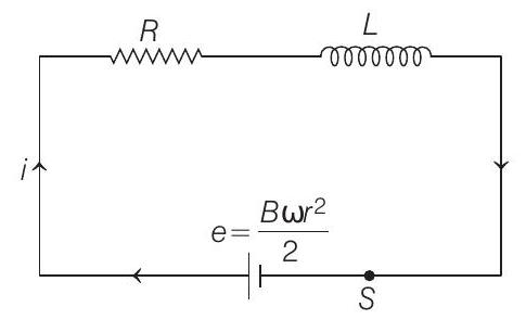
Switch $S$ is closed at time $t=0$. Therefore, it is case of growth of current in an $L-R$ circuit. Current at any time $t$ is given by

$$ \begin{aligned} i & =i _0\left(1-e^{-t / \tau _L}\right), i _0=\frac{e}{R}=\frac{B \omega r^{2}}{2 R} \\ \tau _L & =L / R \\ i & =\frac{B \omega r^{2}}{2 R} 1-e^{-\frac{R}{L} t} \end{aligned} $$

The $i-t$ graph will be as follows

(ii) At constant angular speed, net torque $=0$

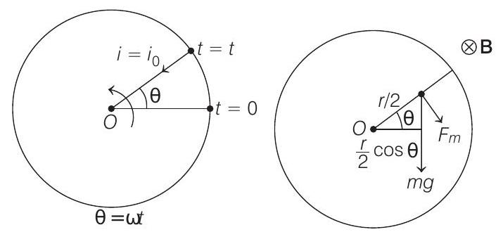
The steady state current will be $i=i _0=\frac{B \omega r^{2}}{2 R}$

From right hand rule, we can see that this current would be inwards (from circumference to centre) and corresponding magnetic force $F _m$ will be in the direction shown in figure and its magnitude is given by

$$ F _m=(i)(r)(B)=\frac{B^{2} \omega r^{3}}{2 R} $$

$\left(\because F _m=i l B\right)$

Torque of this force about centre $O$ is

$$ \tau _{F _m}=F _m \cdot \frac{r}{2}=\frac{B^{2} \omega _r^{4}}{4 R} $$

(clockwise)

Similarly, torque of weight $(mg)$ about centre $O$ is

$$ \tau _{m g}=(m g) \frac{r}{2} \cos \theta=\frac{m g r}{2} \cos \omega t \quad \text { (clockwise) } $$

Therefore, net torque at any time $t$ ( after steady state condition is achieved) about centre $O$ will be

$$ \begin{aligned} \tau _{net} & =\mathrm{\tau} _{F _m}+\tau _{m g} \\ & =\frac{B^{2} \omega r^{4}}{4 R}+\frac{m g r}{2} \cos \omega t \end{aligned} $$

(clockwise)

Hence, the external torque applied to maintain a constant angular speed is $\tau _{ext}=\frac{B^{2} \omega r^{4}}{4 R}+\frac{m g r}{2} \cos \omega t$ (but in anti-clockwise direction).

Note that for $\frac{\pi}{2}<\theta<\frac{3 \pi}{2}$, torque of weight will be anti-clockwise, the sign of which is automatically adjusted because $\cos \theta=$ negative for $\frac{\pi}{2}<\theta<\frac{3 \pi}{2}$.


जेईई के लिए मॉक टेस्ट

एनसीईआरटी अध्याय वीडियो समाधान

दोहरा फलक