Question: Q. 4. Two point charges
(i) Find the electrostatic potential at
(ii) How much work is done in moving a small test charge from the point
(iii) How would your answer change if the path of the test charge between the same points is not along the
(iv) If the above point charges are now placed in the same positions in the uniform external electric field
Justify your answer in each case.
A [Comptt. Delhi/OD I, II, III 2018]
Show Answer
Solution:
Ans. (i) Finding the electrostatic potential
(ii) Finding the work done
(iii) Effect of change of path
(iv) Potential energy of the system
1 (with justification in each case)
(i) We have, for a point charge,
(a) At point
Potential due to the charge
Potential due to the charge
Total Potential at
(b) At point
Potential due to the charge
Potential due to the charge
Total potential at
(ii) Work done
Where
(iii) There would be no change
This is because the electrostatic field is a conservative field.
1
(Alternatively : The work done, in moving a test charge between two given points is independent of the path taken)
(iv) The two given charges make an electric dipole of dipole moment
P.E. in position of unstable equilibrium (where
[CBSE Marking Scheme, 2018]
Revision Notes
Conductors and insulators
Conductors are the materials through which charge can move freely. Examples : metals, semi-metals as carbon, graphite, antimony and arsenic.
- Insulators are materials in which the electrical current will not flow easily. Such materials cannot be grounded and do not easily transfer electrons. Examples : plastics and glass.
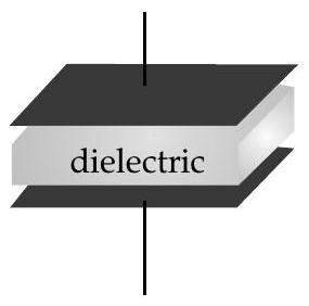
Dielectrics
TOPIC-2
Capacitance
- These are the material in which induced dipole moment is linearly proportional to applied electric field.
- Electrical displacement or electrical flux density
where,
where,
| Material | Dielectric Constant |
Dielectric strength |
|---|---|---|
| Air | 1.00059 | 3 |
| Paper | 3.7 | 16 |
| Pyrex Glass | 5.6 | 14 |
| Water | 80 | - |
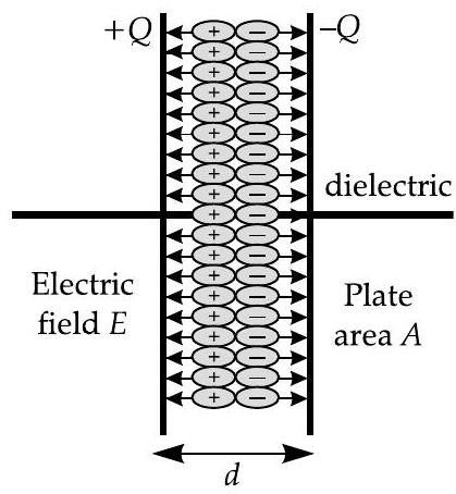
In dielectric, polarisation and production of induced charge takes place when dielectric is kept in an external electric field.
Electric polarization
- Electric polarization
In term of electric susceptibility :
In MKS :
The dielectric constant
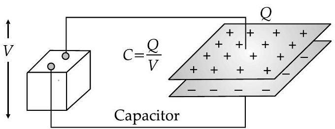
Capacitor
- A capacitor is a device which is used to store charge.
- Amount of charge ’
- Capacitor consists of two similar conducting plates placed in front of each other where one plate is connected to positive terminal while other plate is connected to negative terminal.
- Electric charge stored between plates of capacitor is directly proportional to potential difference between its plates, i.e.,
where,
In capacitor, energy is stored in the form of electrical energy, in the space between the plates.
Capacitance
- Capacitance of a capacitor is ratio of magnitude of charge stored on the plate to potential difference between the plates, written as
where,
stat farad,
Where, stat-farad is electrostatic unit of capacitance in C.G.S. system
Capacitance of a conductor depends on size, shape, medium and other conductors in surrounding.
Parallel plate capacitor with dielectric among its plates has capacitance which is given as :
where,
Capacitor having capacitance 1 Farad is too large for electronics applications, so components with lesser values of capacitance such as
(micro), (nano) and (pico) are applied such as :
| PREFIX | MULTIPLIER | |
|---|---|---|
Combination of capacitors in series and parallel
Capacitors in series
(i) If a number of capacitors of capacitances
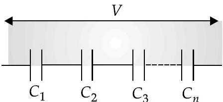
In series combination, the charge on each capacitor is same, but the potential difference on each capacitor depends on their respective capacitance, i.e.,
If
be the potential differences across the capacitors and be the emf of the charging battery, then
As charge on each capacitor is same, therefore
the potential difference is inversely proportional to the capacitance, i.e.,
In series, potential difference across largest capacitance is minimum.
The equivalent capacitance in series combination is less than the smallest capacitance in combination.
Capacitors in parallel
(i) If a number of capacitors of capacitances
- In parallel combination, the potential difference across each capacitor is same and equal to the emf of the charging battery, i.e.,
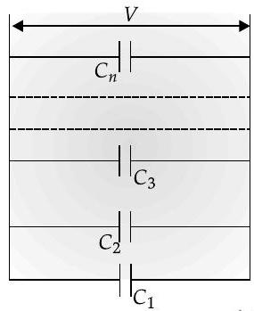
while the charge on different capacitors may be different.
If
As potential drop across each capacitor is same, so
- The charges on capacitors are directly proportional to capacitances, i.e.,
Parallel combination is useful when largecapacitance with large charge gets accumulated on combination.
Force of attraction between parallel plate capacitor will be
where is charge on capacitor.
Capacitance of parallel plate capacitor with and without dielectric medium between the plates
- Parallel plate capacitor is a dapaditor with two identical plane parallel plates separated by a small distance where space between them is filled by dielectric medium
- The electric field between two large parallel plates is given as :
Where,
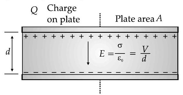
where,
Capacitance of parallel-plate capacitor with area
If a dielectric slab is placed in between the plates of a capacitor, then its capacitance will increase by certain amount.
- Capacitance of parallel plate capacitor depends on plate area
- If we have number of dielectric slabs of same area as the plates of the capacitor and thicknesses
Where,
If slab of conductor of thickness
- When the medium between the plates consists of slabs of same thickness but areas
D When space between the plates is partly filled with medium of thickness
When there is no medium between the plates, then
Capacitance of spherical conductor radius
Energy stored in capacitor
In capacitor, energy gets stored when a work is done on moving a positive charge from negative conductor to positive conductor against the repulsive forces.
Polar atom : Atom in which positive and negative charges possess asymmetric charge distribution about its centre.
Polarisation : The stretching of atoms of a dielectric slab under an applied electric field.
- Dielectric strength : The maximum value of electric field that can be applied to dielectric without its electric breakdown.
Dielectric : It is an electrically insulated or non-conducting material considered for its electric susceptibility.
Permittivity : It is a property of a dielectric medium that shows the forces which electric charges placed in medium exerts on each other.
OR
It is the measure of resistance that is encountered when forming an electric field in a particular medium. More specifically, permittivity describes the amount of charge needed to generate one unit of electric flux in a particular medium.
Key Formulae
Capacitance,
Parallel plate capacitor :
Cylindrical capacitor :
where,
Spherical capacitor :
where,
Maximum charge on a capacitor :
For capacitors connected in series, the charge
Electrical energy stored in a capacitor : [Joules (J)]
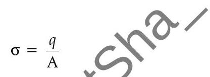
Surface charge density or Charge per unit area
]
Energy density :
- Electric energy density is also called Electrostatic pressure.
- Electric force between plates of capacitor
- Energy stored in terms of Energy density
where,
- Capacitors in series :


