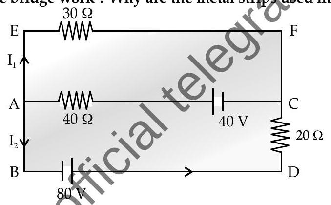
Question: Q. 2. (i) Use Kirchhoff’s rules, calculate the current in the arm
(ii) On what principle does the metre bridge work? Why are the metal strips used in the bridge?
R [O.D. I 2016]
 (b) Meter bridge works on the principle of chectstrubridge. When the
- Ratio of resistances in the adjacent arms are equal, no
- cument flows through the gavanometor and the bridge is said to be balanced The metal strips are used because, they must not contribute to the raistance. When they are thick, their resistances will be low hence minimizing their contribution.
[Topper’s Answer 2016] 5
Q. 3. (i) State Kirchhoff’s rules for an electric network. Using Kirchhoff’s rules, obtain the balance condition in terms of the resistances of four arms of Wheatstone bridge.
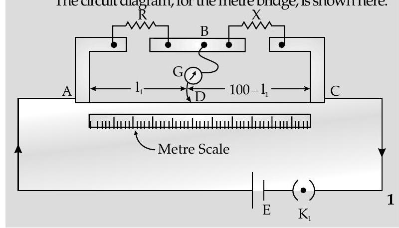
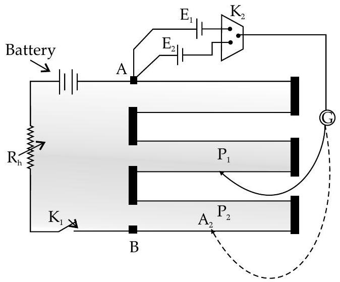
(ii) In the meter bridge experimental set up, shown in the figure, the null point ’
R A [Delhi I, II, III 2014; 2013]
Show Answer
Solution:
Ans. (i) Try yourself Similar to Q. 1, Short Answer Type Questions-I
Try yourself Similar to Q. 2, Short Answer Type Questions-I
(ii)
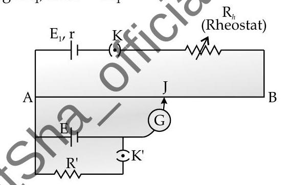
[AI Q. 4. (i) Obtain the condition under which the current flowing, in the current detecting device, used in the circuit shown in the figure, becomes zero.
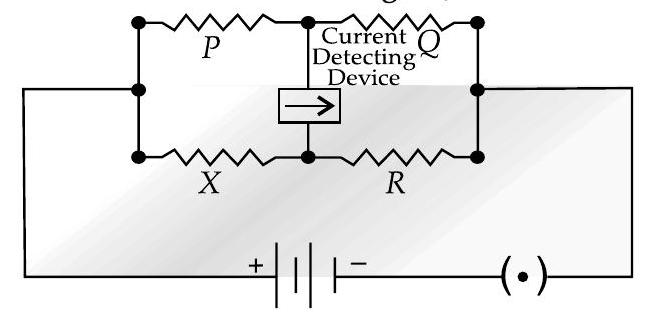
(ii) Describe briefly the device, based on the above question. Draw a circuit diagram for this device and discuss, in brief, how it is used for finding an unknown resistance. U [Foreign Comptt. 2016]
Ans. (i) The given circuit can be redrawn as shown :
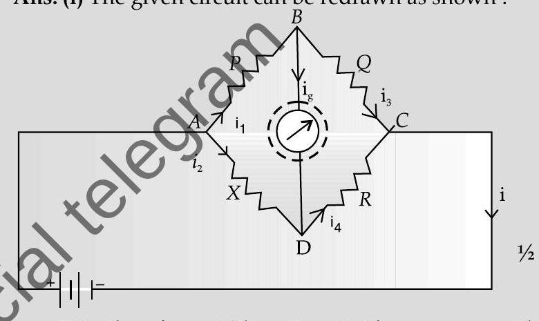
It is, therefore, a Wheatstone Bridge.
For the loop
For the loop
Dividing we get,
(ii) A simple device, based on the above condition, is the metre bridge. It has a (uniform cross-section) wire of length
We move the jockey, on the wire of the meter bridge, till we find a point at which the deflection in
or
Knowing
[CBSE Marking Scheme 2016]

TOPIC-3
Metre Bridge, Potentiometer and their Applications
Revision Notes
Metre Bridge
D It is an instrument which is used to find the unknown resistance of a coil or a material connected in a circuit.
- It is also known as slide wire bridge which is an instrument that works on the principle of Wheatstone bridge.
Metre bridge has two metallic strips which act as holders for the wire that are made of metals like copper.
- Resistance box
- One end of galvanometer is connected to the middle lead of metallic strip placed between
- Jockey which is a metal wire having one end as knife edge is used for sliding on the bridge wire.
Measurement from the Metre bridge :
At negative terminal of galvanometer, there appears zero deflection that makes jockey to connect to negative point on the wire.
- The distance from point
Metre bridge can be drawn similar to Wheatstone bridge as :
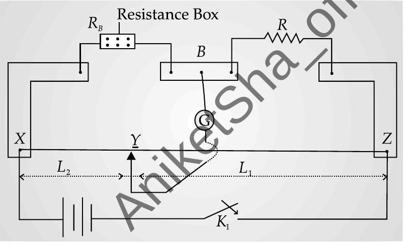
Metre bridge
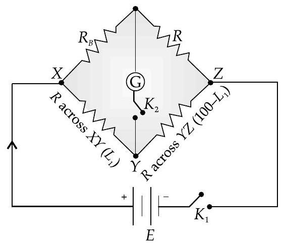
Wheastone bridge
From the above arrangement :
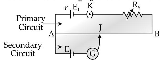
Potentiometer
P Potentiometer is a device which measures the emf of particular cell and helps in comparing the emfs of different cells.
P Potentiometer depends on deflection method where zero deflection results in non drawn of current from the cell or circuit.
It serves as an ideal instrument of infinite resistance for measuring the potential difference.
Potentiometer comprises of long resistive wire
of length (about to long) made up of manganin or constantan.
In this, a battery of known voltage
and internal resistance forms the primary circuit.
In the potentiometer circuit, one terminal of other cell is connected at one end of main circuit while other terminal is connected at any point on the resistive wire through galvanometer
which forms the secondary circuit.
where,
In the circuit :
Specific resistance (
) of wire is high while its temperature coefficient of resistance is low.
- At point
- Value of known potential difference is more than the value of unknown potenthal difference that is to be measured.
The current in primary circuit should remain constant and jockey shouldnot shide with the wire.
Principle of Potentiometer
Potentiometers are displacement sensors that produce electrical butput in proportion to the mechanical displacement.
- It can be used to measure the internal resistance and emf of a cell which cannot be measured by voltmeter.
The basic principle of potentiometer is that the potential drop along any length of the wire is directly proportional to its length. So when a constant current flows through w wire of uniform cross-section and composition then,
When there is zero potential difference between two points, there will be no flow of electric current.
- Applications of Potentiometer : in measuring potential difference and comparing emf of cells Potentiometer in measuring potential difference.
- In a potentiometer auxiliary circuit comprised of battery of emf
- If
- Here, the Galvanometer will show no deflection as potential is same if key
If
Potential drop across potentiometer wire will be :
Now potential gradient of potentiometer wire which is potential per unit length is :
Application of Potentiometer in comparing emf of cells
If a positive terminal of the cell of emf
is connected to terminal while negative terminal is connected to jockey by galvanometer, then by closing the key, jockey will move along the wire and null point is obtained where galvanometer shows no deflection.
When the length of wire
When cell of emf
On comparing and dividing we get an expression :
By knowing the values of
Applications of potentiometer in measurement of internal resistance of gell
(i) Initially in secondary circuit key
(ii) Now key
(iii) By using formula, internal resistance,
Know the Formulae
Potential gradient
Internal resistance of a cell :
Comparison of emf’s of two cells :


