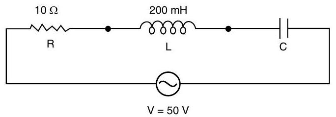
Question: Q. 4. In the following circuit, calculate (i) the capacitance of the capacitor, if the power factor of the circuit is unity, (ii) the Q-factor of this circuit. What is the significance of the Q-factor in ac circuit? Given the angular frequency of the $a c$ source to be $\mathbf{1 0 0}$ $\mathrm{rad} / \mathrm{s}$. Calculate the average power dissipated in the circuit.
A [O.D. Comptt I, II, III 2017]
Show Answer
Solution:
Ans. (i) Calculation of Capacitance
(ii) $Q$-factor of circuit and its importance
(i) As power factor is unity,
$$ \begin{aligned} & \therefore \quad X_{L}=X_{C} \quad 1 / 2 \ & \Rightarrow \quad \omega=\frac{1}{\sqrt{L C}} \end{aligned} $$
$$ \begin{align*} C & =\frac{1}{2 \times 10^{3}} \mathrm{~F} \ & =0.5 \times 10^{-3} \mathrm{~F} \ & =0.5 \mathrm{mF} \end{align*} $$
(ii) Quality factor,
$$ Q=\frac{1}{R} \sqrt{\frac{L}{C}} $$
$$ \begin{aligned} & =\frac{1}{10} \sqrt{\frac{200 \times 10^{-3}}{0 \cdot 5 \times 10^{-3}}} \ & =\frac{1}{10} \times 20=2 \end{aligned} $$
Significance : It measures the sharpness of resonance.
Average Power dissipated,
$$ \begin{aligned} P & =V_{r m s} I_{r m s} \cos \phi \ & =50 \times \frac{50}{10} \times 1 \mathrm{~W} \ & =250 \text { watts } \end{aligned} $$
[CBSE Marking Scheme 2017]
[A] Q. 5. An $a c$ voltage $V=V_{m} \sin \omega t$ is applied to a series LCR circuit. Obtain an expression for the current in the circuit and the phase angle between the current and voltage. What is resonance frequency.
A [SQP I 2017]
Ans. (i) Expression for Current and Phase angle 4
(ii) Resonance Frequency
1
(i) In a series $L C R$ circuit shown,
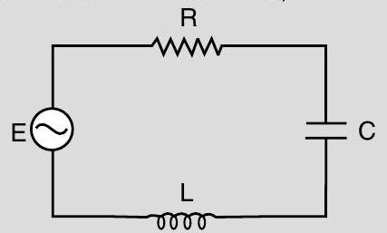
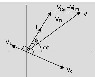
From the phasor relation, voltages $V_{L}+V_{R}+V_{C}=V$, as $V_{C}$ and $V_{L}$ are along the same line and in opposite directions, so they will combine in single phasor $\left(V_{C}+V_{L}\right)$ having magnitude $\left|V_{C m}-V_{L m}\right|$. Since voltage $V$ is shown as hypotenuse of right angled triangle with sides as $V_{R}$ and $\left(V_{C}+V_{L}\right)$, so the Pythagoras Theorem results as :
$$ \begin{aligned} & V_{m}^{2}=V_{R}^{2}+\left(V_{C m}-V_{L m}\right)^{2} \ & V_{m}^{2}=\left(\mathrm{I}{\mathrm{m}} R\right)^{2}+\left(\mathrm{I}{\mathrm{m}} X_{C}-\mathrm{I}{\mathrm{m}} X{L}\right)^{2} \ & V_{m}^{2}=\mathrm{I}{\mathrm{m}}{ }^{2}\left(R^{2}+\left(X{C}-X_{L}\right)^{2}\right) \end{aligned} $$
Now current in the circuit :
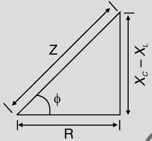
$$ \begin{aligned} & I_{m}=\frac{V_{m}}{\sqrt{\left(R^{2}+\left(X_{C}-X_{L}\right)^{2}\right.}} \ & I_{m}=\frac{V_{m}}{Z} \text { as } Z=\sqrt{\left[R^{2}+\left(X_{C}-X_{L}\right)^{2}\right] \mathbf{1}} \end{aligned} $$
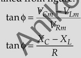
As phasor $I$ is always parallel to phasor $V_{R}$, the phase angle $\phi$ is the angle between $V_{R}$ and $V$ and can be determined from figure.
(ii) Resonance Frequency
Frequencies at which the response amplitude is relative maximum are known as system’s resonant frequencies. It is shown as :
$$ \begin{aligned} V_{C m} & =V_{L m} \ f_{0} & =\frac{1}{2 \pi \sqrt{L C}} \end{aligned} $$
[CBSE Marking Scheme 2017]