Question: Q. 4. A device $X$ is connected across an ac source of voltage $V=V_{0} \sin \omega t$. The current through $X$ is given as $I=I_{0} \sin \left(\omega \mathrm{t}+\frac{\pi}{2}\right)$.

(a) Identify the device $X$ and write the expression for its reactance.

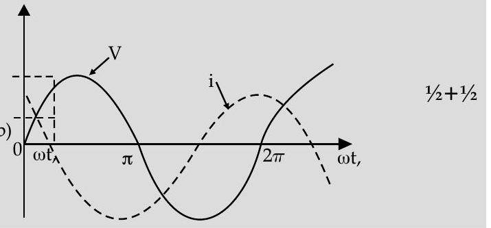
(b) Draw graphs showing variation of voltage and current with time over one cycle of $a c$, for $X$.

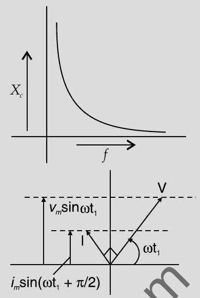
(c) How does the reactance of the device $X$ vary with frequency of the $a c$ ? Show this variation graphically. (d) Draw the phasor diagram for the device $X$.

$\square$ [Delhi & O.D. 2018]

Show Answer

Solution:

Ans. (b) Graphs of voltage and current with time 1+1

(c) Variation of reactance with frequency (Graphical variation)

(d) Phasor Diagram

(a) $X$ : Capacitor

Reactance, $X_{c}=\frac{1}{\omega C}=\frac{1}{2 \pi f C}$

(b)

(c) Reactance of the capacitor varies in inverse proportion to the frequency i.e. , $X_{c} \propto \frac{1}{f}$
[CBSE Marking Scheme 2018]

TOPIC-2
LCR Series Circuit

Revision Notes

$L C R$ series circuit

  • In an LCR series circuit with resistor, inductor andcapacitor, the expression for the instantaneous potential difference between the terminals $a$ and $b$ is given as
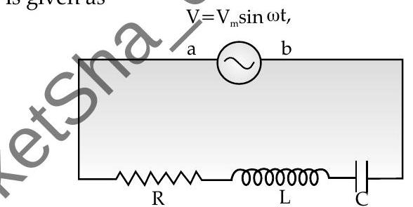
The potential difference in this will be equal to the sum of the potential differences across $R, L$ and $C$ elements as

$$ V=V_{m} \sin \omega t=R I+L \frac{d I}{d t}+\frac{1}{C} q $$

where, $q$ is the charge on capacitor.

The steady state solution will be

$$ i=\frac{V_{m}}{\sqrt{R^{2}+\left(\omega L-\frac{1}{\omega C}\right)^{2}}} \sin (\omega t-\phi) \text { and } i_{m}=\frac{V_{m}}{\sqrt{R^{2}+\left(\omega L-\frac{1}{\omega C}\right)}} $$

where, $\phi=\tan ^{-1} \frac{\omega L-\frac{1}{\omega C}}{R}$

From the equation, steady-state current like terminal voltage, varies sinusoidal with time, so steady-state current can be written as

  • In an LCR circuit :

$$ I=I_{m} \sin (\omega t-\phi) $$

$$ \begin{aligned} & X_{L}=\omega L \ & X_{C}=\frac{1}{\omega C} \ & X=X_{L}-X_{C}=\omega L-\frac{1}{\omega C} \end{aligned} $$

$$ \begin{aligned} & Z=\sqrt{R^{2}+X^{2}} \ & I_{m}=\frac{V_{m}}{\sqrt{R^{2}+\left(X_{I}-X_{C}\right)^{2}}}=\frac{V_{m}}{\sqrt{R^{2}+X^{2}}}=\frac{V_{m}}{Z} \end{aligned} $$

Here, $Z=$ impedance of the circuit, $X=$ reactance, $X_{\mathrm{L}}$ and $X_{C}=$ inductive and capacitive reactance.

For steady-state currents, maximum current $I_{m}$ is related to maximum potential difference $V_{m}$ by

$$ I_{m}=\frac{V_{m}}{Z} $$

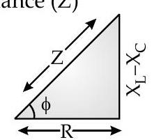
Total effective resistance of $R L C$ circuit is called Impedance $(Z)$ of the circuit given as

$$ Z=\sqrt{R^{2}+\left(X_{L}-X_{C}\right)^{2}} $$

The angle by which alternating voltage leads the alternating current in $R L C$ circuit is given by

$$ \tan \phi=\frac{X_{L}-X_{C}}{R} $$

In an $R L C$ circuit, impedance triangle is a right-angled triangle in which base is ohmic resistance $R$, perpendicular is reactance $\left(X_{L}-X_{C}\right)$ and hypotenuse is impedance $(Z)$

When a condenser of capacity $C$ charged to certain potential is connected to inductor $L$, energy stored in $C$ oscillates between $L$ and $C$ where frequency of energy oscillations is given by

$$ X_{L}=X_{C} \text { or } \quad f=\frac{1}{2 \pi \sqrt{L C}} $$

In LCR circuit, if there is no loss of energy, then totalenergy in $L$ and $C$ at every instant will remain constant.

$>$ Sign for phase difference $(\phi)$ between $I$ and $E$ for aséries $L C R$ circuit :

$$ \begin{array}{ll} \phi \text { is positive, when } X_{L}>X_{C} \ \phi \text { is negative, when } X_{L}<X_{C} . \ \phi \text { is zero, } & \text { when } X_{L}=X_{C} . \ \phi=\pi / 2, & \text { when } \omega=\infty . \ \phi=-\pi / 2, & \text { when } \omega=0 . \end{array} $$

Resonance

Circuit in which inductance L,Capacitance $C$ and resistance $R$ are connected in series and the circuit admits maximum current, then such circuit is called as series resonant circuit.

The necessary conditionfor resonance in $L C R$ series circuit is : $V_{C}=V_{L}$

$$ X_{L}=X_{C} \text { which gives } \omega^{2}=\frac{1}{L C} \text { or } f=\frac{1}{2 \pi \sqrt{L C}} $$

In this, frequency of $a c$ fed to circuit will be equal to natural frequency of energy oscillations in the circuit under conditions,

$$ \begin{aligned} & Z=R \ & I_{0}=\frac{E_{0}}{Z}=\frac{E_{0}}{R} \end{aligned} $$

The sharpness of tuning at resonance is measured by $Q$ factor or quality factor of the circuit given as

$$ Q=\frac{1}{R} \sqrt{\frac{L}{C}} $$

At series LCR resonance or acceptor circuit, current is maximum.

$$ I_{\max }=\frac{E}{R} $$

Power in AC circuits

$>$ When the current is out of phase with the voltage, the power indicated by the product of the applied voltage and the total current gives only what is known as apparent power.

$>$ If. the instantaneous values of the voltage and current in an ac circuit are given by

$$ \begin{gathered} E=E_{0} \sin \omega t \ i=i_{0} \sin (\omega t-\phi) \end{gathered} $$

where $\phi$ is the phase difference between voltage and the current. Then the instantaneous power or average power

$$ \begin{aligned} P_{i n} & =E \times i=E_{0} i_{0} \sin \omega t \cdot \sin (\omega t-\phi) \ P_{a v g} & =\frac{1}{2} E_{0} i_{0} \cos \phi \ & =\frac{E_{0}}{\sqrt{2}} \times \frac{i_{0}}{\sqrt{2}} \cos \phi=V_{r m s} \times I_{r m s} \times \cos \phi \end{aligned} $$

where, $\cos \phi$ is known as power factor.

Power factor $(\cos \phi)$ is important in power systems as it shows how closely the effective power equals the apparent power given as :

$$ \cos \phi=\frac{\text { effective power }}{\text { apparent power }} $$

  • The value of power factor varies from 0 to 1 .

The instantaneous rate at which energy is supplied to an electrical device by ac circuit is

$$ P=V I $$

Average power in $R L C$ where, $X_{L}=X_{C}$ over a complete cycle in a non inductive circuit or pure resistive circuit is given as $\quad P=V_{0} I_{0}$ or $I_{0}^{2} R$

Wattless Current

  • The average power associated over a complete cycle with pure inductor or pare capacitor is zero which makes current through $L$ and $C$ as wattless or idle current.

In $L C R$ circuit at resonance, the power loss is maximum, so

Dattless component of current $=I_{r m s} \sin \phi$

$>$ Power component of current $=I_{r m s} \cos \phi$

Phase angle : It is the amount by which the voltage and current are of phase with each other in a circuit.

Power factor : It is the amount by which the power delivered in the circuit is less than the theoretical maximum of the circuit due to voltage and current being out of phase.

Quality factor : It is a dimensionless quantity that shows sharphess of the peak of bandwidth.

Resonant frequency : It is the frequency at which the amplitude of the current is maximum where circuit oscillates when not driven by voltage source.

Know the Formulae

  • Impedance for a series $L C R$ circuit,

Average power,

Power factor,

Quality factor

$$ \begin{aligned} Z & =\sqrt{R^{2}+X^{2}}=\left[R^{2}+\left(\omega L-\frac{1}{\omega C}\right)^{2}\right]^{1 / 2} . \ P & =\frac{E_{0} I_{0}}{2} \cos \phi=V_{r m s} I_{r m s} \cos \phi \ P F=\cos \phi & =\frac{\text { Resistance }}{\text { Impedance }}=\frac{R}{Z}=\frac{\text { True power }}{\text { Apparent power }} \ \phi & =\frac{1}{R} \sqrt{\frac{L}{C}} \end{aligned} $$

? Objective Type Question


विषयसूची

जेईई के लिए मॉक टेस्ट

एनसीईआरटी अध्याय वीडियो समाधान

दोहरा फलक