Chapter-09 Light – Reflection and Refraction
We see a variety of objects in the world around us. However, we are unable to see anything in a dark room. On lighting up the room, things become visible. What makes things become visible. What makes things visible? During the day, the sunlight helps us to see objects. An object reflects light that falls on it. This reflected light, when received by our eyes, enables us to see things. We are able to see through a transparent medium as light is transmitted through it. There are a number of common wonderful phenomena associated with light such as image formation by mirrors, the twinkling of stars, the beautiful colours of a rainbow, bending of light by a medium and so on. A study of the properties of light helps us to explore them.
By observing the common optical phenomena around us, we may conclude that light seems to travel in straight lines. The fact that a small source of light casts a sharp shadow of an opaque object points to this straight-line path of light, usually indicated as a ray of light.
More to Know!
If an opaque object on the path of light becomes very small, light has a tendency to bend around it and not walk in a straight line - an effect known as the diffraction of light. Then the straight-line treatment of optics using rays fails. To explain phenomena such as diffraction, light is thought of as a wave, the details of which you will study in higher classes. Again, at the beginning of the $20^{\text{th }}$ century, it became known that the wave theory of light often becomes inadequate for treatment of the interaction of light with matter, and light often behaves somewhat like a stream of particles. This confusion about the true nature of light continued for some years till a modern quantum theory of light emerged in which light is neither a ‘wave’ nor a ‘particle’ - the new theory reconciles the particle properties of light with the wave nature.
In this Chapter, we shall study the phenomena of reflection and refraction of light using the straight-line propagation of light. These basic concepts will help us in the study of some of the optical phenomena in nature. We shall try to understand in this Chapter the reflection of light by spherical mirrors and refraction of light and their application in real life situations.
9.1 REFLECTION OF LIGHT
A highly polished surface, such as a mirror, reflects most of the light falling on it. You are already familiar with the laws of reflection of light.
Let us recall these laws -
(i) The angle of incidence is equal to the angle of reflection, and
(ii) The incident ray, the normal to the mirror at the point of incidence and the reflected ray, all lie in the same plane.
These laws of reflection are applicable to all types of reflecting surfaces including spherical surfaces. You are familiar with the formation of image by a plane mirror. What are the properties of the image? Image formed by a plane mirror is always virtual and erect. The size of the image is equal to that of the object. The image formed is as far behind the mirror as the object is in front of it. Further, the image is laterally inverted. How would the images be when the reflecting surfaces are curved? Let us explore.
Activity 9.1
- Take a large shining spoon. Try to view your face in its curved surface.
- Do you get the image? Is it smaller or larger?
- Move the spoon slowly away from your face. Observe the image. How does it change?
- Reverse the spoon and repeat the Activity. How does the image look like now?
- Compare the characteristics of the image on the two surfaces.
The curved surface of a shining spoon could be considered as a curved mirror. The most commonly used type of curved mirror is the spherical mirror. The reflecting surface of such mirrors can be considered to form a part of the surface of a sphere. Such mirrors, whose reflecting surfaces are spherical, are called spherical mirrors. We shall now study about spherical mirrors in some detail.
9.2 SPHERICAL MIRRORS
The reflecting surface of a spherical mirror may be curved inwards or outwards. A spherical mirror, whose reflecting surface is curved inwards, that is, faces towards the centre of the sphere, is called a concave mirror. A spherical mirror whose reflecting surface is curved outwards, is called a convex mirror. The schematic representation of these mirrors is shown in Fig. 9.1. You may note in these diagrams that the back of the mirror is shaded.
You may now understand that the surface of the spoon curved inwards can be approximated to a concave mirror and the surface of the spoon bulged outwards can be approximated to a convex mirror.
Before we move further on spherical mirrors, we need to recognise and understand the meaning of a few terms. These terms are commonly used in discussions about spherical mirrors. The centre of the reflecting surface of a spherical mirror is a point called the pole. It lies on the surface of the mirror. The pole is usually represented by the letter $P$.

Figure 9.1 Schematic representation of spherical mirrors; the shaded side is non-reflecting.
The reflecting surface of a spherical mirror forms a part of a sphere. This sphere has a centre. This point is called the centre of curvature of the spherical mirror. It is represented by the letter $C$. Please note that the centre of curvature is not a part of the mirror. It lies outside its reflecting surface. The centre of curvature of a concave mirror lies in front of it. However, it lies behind the mirror in case of a convex mirror. You may note this in Fig. 9.2 (a) and (b). The radius of the sphere of which the reflecting surface of a spherical mirror forms a part, is called the radius of curvature of the mirror. It is represented by the letter $R$. You may note that the distance PC is equal to the radius of curvature. Imagine a straight line passing through the pole and the centre of curvature of a spherical mirror. This line is called the principal axis. Remember that principal axis is normal to the mirror at its pole. Let us understand an important term related to mirrors, through an Activity.
Activity 9.2
CAUTION: Do not look at the Sun directly or even into a mirror reflecting sunlight. It may damage your eyes.
- Hold a concave mirror in your hand and direct its reflecting surface towards the Sun.
- Direct the light reflected by the mirror on to a sheet of paper held close to the mirror.
- Move the sheet of paper back and forth gradually until you find on the paper sheet a bright, sharp spot of light.
- Hold the mirror and the paper in the same position for a few minutes. What do you observe? Why?
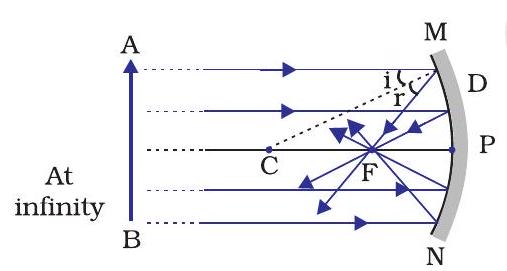
The paper at first begins to burn producing smoke. Eventually it may even catch fire. Why does it burn? The light from the Sun is converged at a point, as a sharp, bright spot by the mirror. In fact, this spot of light is the image of the Sun on the sheet of paper. This point is the focus of the concave mirror. The heat produced due to the concentration of sunlight ignites the paper. The distance of this image from the position of the mirror gives the approximate value of focal length of the mirror.
(a)
(b)
Figure 9.2 (a) Concave mirror (b) Convex mirror
Let us try to understand this observation with the help of a ray diagram.
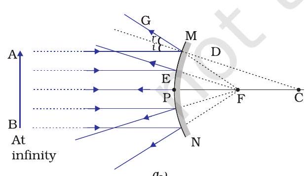
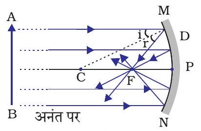
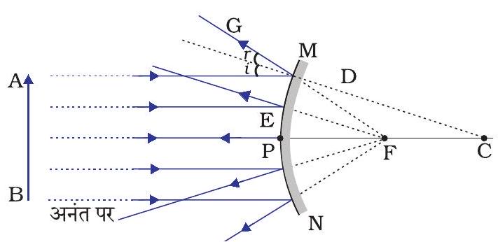
Observe Fig.9.2 (a) closely. A number of rays parallel to the principal axis are falling on a concave mirror. Observe the reflected rays. They are all meeting/intersecting at a point on the principal axis of the mirror. This point is called the principal focus of the concave mirror. Similarly, observe Fig. 9.2 (b). How are the rays parallel to the principal axis, reflected by a convex mirror? The reflected rays appear to come from a point on the principal axis. This point is called the principal focus of the convex mirror. The principal focus is represented by the letter $F$. The distance between the pole and the principal focus of a spherical mirror is called the focal length. It is represented by the letter $f$.
The reflecting surface of a spherical mirror is by-and-large spherical. The surface, then, has a circular outline. The diameter of the reflecting surface of spherical mirror is called its aperture. In Fig.9.2, distance MN represents the aperture. We shall consider in our discussion only such spherical mirrors whose aperture is much smaller than its radius of curvature.
Is there a relationship between the radius of curvature $R$, and focal length $f$, of a spherical mirror? For spherical mirrors of small apertures, the radius of curvature is found to be equal to twice the focal length. We put this as $R=2 f$. This implies that the principal focus of a spherical mirror lies midway between the pole and centre of curvature.
9.2.1 Image Formation by Spherical Mirrors
You have studied about the image formation by plane mirrors. You also know the nature, position and relative size of the images formed by them. How about the images formed by spherical mirrors? How can we locate the image formed by a concave mirror for different positions of the object? Are the images real or virtual? Are they enlarged, diminished or have the same size? We shall explore this with an Activity.
Activity 9.3
- You have already learnt a way of determining the focal length of a concave mirror. In Activity 9.2, you have seen that the sharp bright spot of light you got on the paper is, in fact, the image of the Sun. It was a tiny, real, inverted image. You got the approximate focal length of the concave mirror by measuring the distance of the image from the mirror.
- Take a concave mirror. Find out its approximate focal length in the way described above. Note down the value of focal length. (You can also find it out by obtaining image of a distant object on a sheet of paper.)
- Mark a line on a Table with a chalk. Place the concave mirror on a stand. Place the stand over the line such that its pole lies over the line.
- Draw with a chalk two more lines parallel to the previous line such that the distance between any two successive lines is equal to the focal length of the mirror. These lines will now correspond to the positions of the points $P, F$ and $C$, respectively. Remember For a spherical mirror of small aperture, the principal focus $F$ lies mid-way between the pole $P$ and the centre of curvature $C$.
- Keep a bright object, say a burning candle, at a position far beyond C. Place a paper screen and move it in front of the mirror till you obtain a sharp bright image of the candle flame on it.
- Observe the image carefully. Note down its nature, position and relative size with respect to the object size.
- Repeat the activity by placing the candle - (a) just beyond C, (b) at $C$, (c) between $F$ and $C$, (d) at $F$, and (e) between $P$ and $F$.
- In one of the cases, you may not get the image on the screen. Identify the position of the object in such a case. Then, look for its virtual image in the mirror itself.
- Note down and tabulate your observations.
You will see in the above Activity that the nature, position and size of the image formed by a concave mirror depends on the position of the object in relation to points $P, F$ and $C$. The image formed is real for some positions of the object. It is found to be a virtual image for a certain other position. The image is either magnified, reduced or has the same size, depending on the position of the object. A summary of these observations is given for your reference in Table 9.1.
Table 9.1 Image formation by a concave mirror for different positions of the object
| Position of the object | Position of the image | Size of the image Highly diminished, point-sized | Nature of the image |
|---|---|---|---|
| At infinity | At the focus F | Diminished | Real and inverted |
| Beyond C | Between F and C | Same size | Real and inverted |
| At C | At C | Enlarged | Real and inverted |
| Between C and F | Beyond C | Highly enlarged | Real and inverted |
| At F | At infinity | Enlarged | Virtual and erect |
| Between P and F | Behind the mirror |
9.2.2 Representation of Images Formed by Spherical Mirrors Using Ray Diagrams
We can also study the formation of images by spherical mirrors by drawing ray diagrams. Consider an extended object, of finite size, placed in front of a spherical mirror. Each small portion of the extended object acts like a point source. An infinite number of rays originate from each of these points. To construct the ray diagrams, in order to locate the image of an object, an arbitrarily large number of rays emanating from a point could be considered. However, it is more convenient to consider only two rays, for the sake of clarity of the ray diagram. These rays are so chosen that it is easy to know their directions after reflection from the mirror.
The intersection of at least two reflected rays give the position of image of the point object. Any two of the following rays can be considered for locating the image.
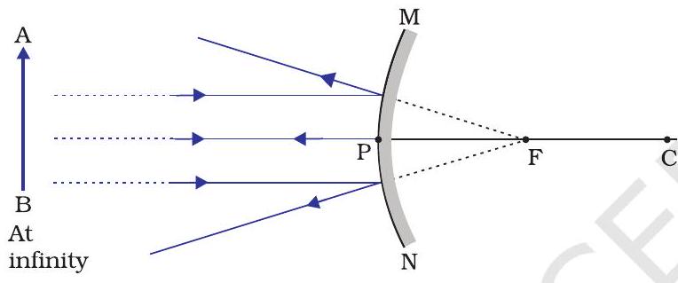
(i) A ray parallel to the principal axis, after reflection, will pass through the principal focus in case of a concave mirror or appear to diverge from the principal focus in case of a convex mirror. This is illustrated in Fig.9.3 (a) and (b).

Figure 9.3
(ii) A ray passing through the principal focus of a concave mirror or a ray which is directed towards the principal focus of a convex mirror, after reflection, will emerge parallel to the principal axis. This is illustrated in Fig. 9.4 (a) and (b).

Figure 9.4
(iii) A ray passing through the centre of curvature of a concave mirror or directed in the direction of the centre of curvature of a convex mirror, after reflection, is reflected back along the same path. This is illustrated in Fig. 9.5 (a) and (b). The light rays come back along the same path because the incident rays fall on the mirror along the normal to the reflecting surface.

Figure 9.5
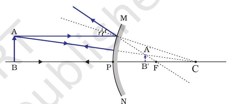
(iv) A ray incident obliquely to the principal axis, towards a point $P$ (pole of the mirror), on the concave mirror [Fig. 9.6 (a)] or a convex mirror [Fig. 9.6 (b)], is reflected obliquely. The incident and reflected rays follow the laws of reflection at the point of incidence

Figure 9.6
Remember that in all the above cases the laws of reflection are followed. At the point of incidence, the incident ray is reflected in such a way that the angle of reflection equals the angle of incidence.
(a) Image formation by Concave Mirror
Figure 9.7 illustrates the ray diagrams for the formation of image by a concave mirror for various positions of the object.

Figure 9.7 Ray diagrams for the image formation by a concave mirror
Activity 9.4
- Draw neat ray diagrams for each position of the object shown in Table 9.1.
- You may take any two of the rays mentioned in the previous section for locating the image.
- Compare your diagram with those given in Fig. 9.7.
- Describe the nature, position and relative size of the image formed in each case.
- Tabulate the results in a convenient format.
Uses of concave mirrors
Concave mirrors are commonly used in torches, search-lights and vehicles headlights to get powerful parallel beams of light. They are often used as shaving mirrors to see a larger image of the face. The dentists use concave mirrors to see large images of the teeth of patients. Large concave mirrors are used to concentrate sunlight to produce heat in solar furnaces.
(b) Image formation by a Convex Mirror
We studied the image formation by a concave mirror. Now we shall study the formation of image by a convex mirror.
Activity 9.5
- Take a convex mirror. Hold it in one hand.
- Hold a pencil in the upright position in the other hand.
- Observe the image of the pencil in the mirror. Is the image erect or inverted? Is it diminished or enlarged?
- Move the pencil away from the mirror slowly. Does the image become smaller or larger?
- Repeat this Activity carefully. State whether the image will move closer to or farther away from the focus as the object is moved away from the mirror?
We consider two positions of the object for studying the image formed by a convex mirror. First is when the object is at infinity and the second position is when the object is at a finite distance from the mirror. The ray diagrams for the formation of image by a convex mirror for these two positions of the object are shown in Fig. 9.8 (a) and (b), respectively. The results are summarised in Table 9.2.
(a)
(b)
Figure 9.8 Formation of image by a convex mirror
Table 9.2 Nature, position and relative size of the image formed by a convex mirror
| Position of the object | Position of the image | Size of the image | Nature of the image |
|---|---|---|---|
| At infinity | At the focus F, behind the mirror | Highly diminished, point-sized | Virtual and erect |
| Between infinity and the pole P of the mirror | Between P and F, behind the mirror | Diminished | Virtual and erect |
You have so far studied the image formation by a plane mirror, a concave mirror and a convex mirror. Which of these mirrors will give the full image of a large object? Let us explore through an Activity.
Activity 9.6
- Observe the image of a distant object, say a distant tree, in a plane mirror.
- Could you see a full-length image?
- Try with plane mirrors of different sizes. Did you see the entire object in the image?
- Repeat this Activity with a concave mirror. Did the mirror show full length image of the object?
- Now try using a convex mirror. Did you succeed? Explain your observations with reason.
You can see a full-length image of a tall building/tree in a small convex mirror. One such mirror is fitted in a wall of Agra Fort facing Taj Mahal. If you visit the Agra Fort, try to observe the full image of Taj Mahal. To view distinctly, you should stand suitably at the terrace adjoining the wall.
Uses of convex mirrors
Convex mirrors are commonly used as rear-view (wing) mirrors in vehicles. These mirrors are fitted on the sides of the vehicle, enabling the driver to see traffic behind him/her to facilitate safe driving. Convex mirrors are preferred because they always give an erect, though diminished, image. Also, they have a wider field of view as they are curved outwards. Thus, convex mirrors enable the driver to view much larger area than would be possible with a plane mirror.
Questions
1. Define the principal focus of a concave mirror.
Show Answer
Answer
Light rays that are parallel to the principal axis of a concave mirror converge at a specific point on its principal axis after reflecting from the mirror. This point is known as the principal focus of the concave mirror.
2. The radius of curvature of a spherical mirror is 20 cm. What is its focal length?
Show Answer
Answer
Radius of curvature, $R=20 cm$
Radius of curvature of a spherical mirror $=2 \times$ Focal length ( $f$ )
$R=2 f$
$f=\dfrac{R}{2}=\dfrac{20}{2}=10 cm$
Hence, the focal length of the given spherical mirror is $10 cm$.
3. Name a mirror that can give an erect and enlarged image of an object.
Show Answer
Answer
When an object is placed between the pole and the principal focus of a concave mirror, the image formed is virtual, erect, and enlarged.
4. Why do we prefer a convex mirror as a rear-view mirror in vehicles?
Show Answer
Answer
Convex mirrors give a virtual, erect, and diminished image of the objects placed in front of them. They are preferred as a rear-view mirror in vehicles because they give a wider field of view, which allows the driver to see most of the traffic behind him.
9.2.3 Sign Convention for Reflection by Spherical Mirrors
While dealing with the reflection of light by spherical mirrors, we shall follow a set of sign conventions called the New Cartesian Sign Convention. In this convention, the pole (P) of the mirror is taken as the origin (Fig. 9.9). The principal axis of the mirror is taken as the $x$-axis (X’X) of the coordinate system. The conventions are as follows -
(i) The object is always placed to the left of the mirror. This implies that the light from the object falls on the mirror from the left-hand side.
(ii) All distances parallel to the principal axis are measured from the pole of the mirror.
(iii) All the distances measured to the right of the origin (along $+x$-axis) are taken as positive while those measured to the left of the origin (along - $x$-axis) are taken as negative.
(iv) Distances measured perpendicular to and above the principal axis (along $+y$-axis) are taken as positive.
(v) Distances measured perpendicular to and below the principal axis (along $-y$-axis) are taken as negative.
The New Cartesian Sign Convention described above is illustrated in Fig.9.9 for your reference. These sign conventions are applied to obtain the mirror formula and solve related numerical problems.
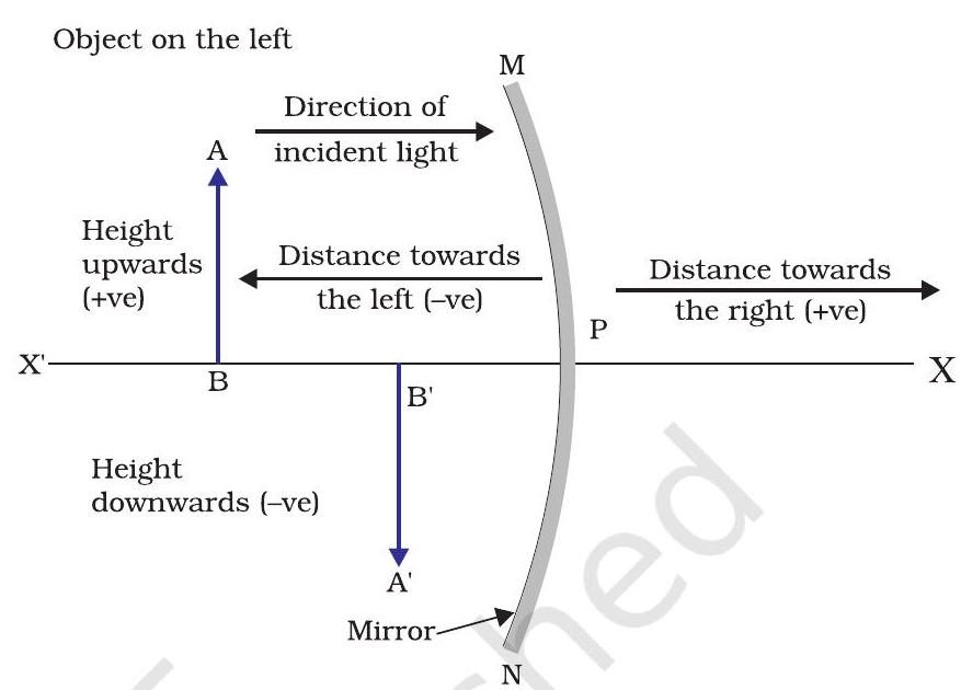
Figure 9.9 The New Cartesian Sign Convention for spherical mirrors
9.2.4 Mirror Formula and Magnification
In a spherical mirror, the distance of the object from its pole is called the object distance $(u)$. The distance of the image from the pole of the mirror is called the image distance $(v)$. You already know that the distance of the principal focus from the pole is called the focal length $(f)$. There is a relationship between these three quantities given by the mirror formula which is expressed as
$$\dfrac{1}{v}+\dfrac{1}{u}=\dfrac{1}{f} \tag {9.1}$$
This formula is valid in all situations for all spherical mirrors for all positions of the object. You must use the New Cartesian Sign Convention while substituting numerical values for $u, v, f$, and $R$ in the mirror formula for solving problems.
Magnification
Magnification produced by a spherical mirror gives the relative extent to which the image of an object is magnified with respect to the object size. It is expressed as the ratio of the height of the image to the height of the object. It is usually represented by the letter $m$.
If $h$ is the height of the object and $h^{\prime}$ is the height of the image, then the magnification $m$ produced by a spherical mirror is given by
$$ \begin{align*} & m=\dfrac{\text { Height of the image }\left(h^{\prime}\right)}{\text { Height of the object }(h)} \\ & m=\dfrac{h^{\prime}}{h} \tag{9.2} \end{align*} $$
The magnification $m$ is also related to the object distance $(u)$ and image distance $(v)$. It can be expressed as:
$$ \begin{equation*} \text { Magnification }(m)=\dfrac{h}{h}=-\dfrac{v}{u} \tag{9.3} \end{equation*} $$
You may note that the height of the object is taken to be positive as the object is usually placed above the principal axis. The height of the image should be taken as positive for virtual images. However, it is to be taken as negative for real images. A negative sign in the value of the magnification indicates that the image is real. A positive sign in the value of the magnification indicates that the image is virtual.
Example 9.1
A convex mirror used for rear-view on an automobile has a radius of curvature of $3.00 m$. If a bus is located at $5.00 m$ from this mirror, find the position, nature and size of the image.
Solution
Radius of curvature, $R=+3.00 m$;
Object-distance, $\quad u=-5.00 m$;
Image-distance, $\quad v=$ ?
Height of the image, $h^{\prime}=$ ?
Focal length, $f=R / 2=+\dfrac{3.00 m}{2}=+1.50 m$ (as the principal focus of a convex mirror is behind the mirror)
Since $\dfrac{1}{v}+\dfrac{1}{u}=\dfrac{1}{f}$
or, $\dfrac{1}{v}=\dfrac{1}{f}-\dfrac{1}{u}=+\dfrac{1}{1.50}-\dfrac{1}{(-5.00)}=\dfrac{1}{1.50}+\dfrac{1}{5.00}$
$=\dfrac{5.00+1.50}{7.50}$
$v=\dfrac{+7.50}{6.50}=+1.15 m$
The image is $1.15 m$ at the back of the mirror.
Magnification, $m=\dfrac{h^{\prime}}{h}=-\dfrac{v}{u}=-\dfrac{1.15 m}{-5.00 m}$
$$ =+0.23 $$
The image is virtual, erect and smaller in size by a factor of 0.23 .
Example 9.2
An object, $4.0 cm$ in size, is placed at $25.0 cm$ in front of a concave mirror of focal length $15.0 cm$. At what distance from the mirror should a screen be placed in order to obtain a sharp image? Find the nature and the size of the image.
Solution
Object-size, $h=+4.0 cm$;
Object-distance, $u=-25.0 cm$;
Focal length, $f=-15.0 cm$;
Image-distance, $v=$ ?
Image-size, $h^{\prime}=$ ?
From Eq. (10.1):
$ \begin{aligned} & \dfrac{1}{v}+\dfrac{1}{u}=\dfrac{1}{f} \\ & \text{ or, } \dfrac{1}{v}=\dfrac{1}{f}-\dfrac{1}{u}=\dfrac{1}{-15.0}-\dfrac{1}{-25.0}=-\dfrac{1}{15.0}+\dfrac{1}{25.0} \end{aligned} $
or, $\dfrac{1}{v}=\dfrac{-5.0+3.0}{75.0}=\dfrac{-2.0}{75.0}$ or, $v=-37.5 cm$
The screen should be placed at $37.5 \mathrm{~cm}$ in front of the mirror. The image is real.
Also, magnification, $m=\dfrac{h^{\prime}}{h}=-\dfrac{v}{u}$
or, $h^{\prime}=-\dfrac{v h}{u}=-\dfrac{(-37.5 \mathrm{~cm})(+4.0 \mathrm{~cm})}{(-25.0 \mathrm{~cm})}$
Height of the image, $h^{\prime}=-6.0 \mathrm{~cm}$
The image is inverted and enlarged.
Questions
1. Find the focal length of a convex mirror whose radius of curvature is $32 cm$.
Show Answer
Answer
Radius of curvature, $R=32 cm$
Radius of curvature $=2 \times$ Focal length $(f)$
$R=2 f$
$f=\dfrac{R}{2}=\dfrac{32}{2}=16 cm$
Hence, the focal length of the given convex mirror is $16 cm$.
2. A concave mirror produces three times magnified (enlarged) real image of an object placed at $10 cm$ in front of it. Where is the image located?
Show Answer
Answer
Magnification produced by a spherical mirror is given by the relation,
$m=\dfrac{\text{ Height of the image }}{\text{ Height of the object }}=-\dfrac{\text{ Image distance }}{\text{ Object distance }}$
$m=\dfrac{h_1}{h_0}=-\dfrac{v}{u}$
Let the height of the object, ho $=h$
Then, height of the image, $hI=-3 h$ (Image formed is real)
$ \begin{aligned} & \dfrac{-3 h}{h}=\dfrac{-v}{u} \\ & \dfrac{v}{u}=3 \end{aligned} $
Object distance, $u=-10 cm$
$v=3 \times(-10)=-30 cm$
Here, the negative sign indicates that an inverted image is formed at a distance of 30 $cm$ in front of the given concave mirror.
9.3 REFRACTION OF LIGHT
Light seems to travel along straight-line paths in a transparent medium. What happens when light enters from one transparent medium to another? Does it still move along a straight-line path or change its direction? We shall recall some of our day-to-day experiences.
You might have observed that the bottom of a tank or a pond containing water appears to be raised. Similarly, when a thick glass slab is placed over some printed matter, the letters appear raised when viewed through the glass slab. Why does it happen? Have you seen a pencil partly immersed in water in a glass tumbler? It appears to be displaced at the interface of air and water. You might have observed that a lemon kept in water in a glass tumbler appears to be bigger than its actual size, when viewed from the sides. How can you account for such experiences?
Let us consider the case of the apparent displacement of a pencil, partly immersed in water. The light reaching you from the portion of the pencil inside water seems to come from a different direction, compared to the part above water. This makes the pencil appear to be displaced at the interface. For similar reasons, the letters appear to be raised, when seen through a glass slab placed over it.
Does a pencil appear to be displaced to the same extent, if instead of water, we use liquids like kerosene or turpentine? Will the letters appear to rise to the same height if we replace a glass slab with a transparent plastic slab? You will find that the extent of the effect is different for different pair of media. These observations indicate that light does not travel in the same direction in all media. It appears that when travelling obliquely from one medium to another, the direction of propagation of light in the second medium changes. This phenomenon is known as refraction of light. Let us understand this phenomenon further by doing a few activities.
Activity 9.7
- Place a coin at the bottom of a bucket filled with water.
- With your eye to a side above water, try to pick up the coin in one go. Did you succeed in picking up the coin?
- Repeat the Activity. Why did you not succeed in doing it in one go?
- Ask your friends to do this. Compare your experience with theirs.
Activity 9.8
- Place a large shallow bowl on a Table and put a coin in it.
- Move away slowly from the bowl. Stop when the coin just disappears from your sight.
- Ask a friend to pour water gently into the bowl without disturbing the coin.
- Keep looking for the coin from your position. Does the coin becomes visible again from your position? How could this happen?
The coin becomes visible again on pouring water into the bowl. The coin appears slightly raised above its actual position due to refraction of light.
Activity 9.9
- Draw a thick straight line in ink, over a sheet of white paper placed on a Table.
- Place a glass slab over the line in such a way that one of its edges makes an angle with the line.
- Look at the portion of the line under the slab from the sides. What do you observe? Does the line under the glass slab appear to be bent at the edges?
- Next, place the glass slab such that it is normal to the line. What do you observe now? Does the part of the line under the glass slab appear bent?
- Look at the line from the top of the glass slab. Does the part of the line, beneath the slab, appear to be raised? Why does this happen?
9.3.1 Refraction through a Rectangular Glass Slab
To understand the phenomenon of refraction of light through a glass slab, let us do an Activity.
Activity 9.10
- Fix a sheet of white paper on a drawing board using drawing pins.
- Place a rectangular glass slab over the sheet in the middle.
- Draw the outline of the slab with a pencil. Let us name the outline as $ABCD$.
- Take four identical pins.
- Fix two pins, say $E$ and $F$, vertically such that the line joining the pins is inclined to the edge AB.
- Look for the images of the pins $E$ and $F$ through the opposite edge. Fix two other pins, say $G$ and $H$, such that these pins and the images of $E$ and $F$ lie on a straight line.
- Remove the pins and the slab.
- Join the positions of tip of the pins $E$ and $F$ and produce the line up to $AB$. Let $EF$ meet $AB$ at $O$. Similarly, join the positions of tip of the pins $G$ and $H$ and produce it up to the edge $CD$. Let $HG$ meet $CD$ at $O^{\prime}$.
- Join $O$ and $O^{\prime}$. Also produce $EF$ up to $P$, as shown by a dotted line in Fig. 9.10.
In this Activity, you will note, the light ray has changed its direction at points $O$ and $O^{\prime}$. Note that both the points $O$ and $O^{\prime}$ lie on surfaces separating two transparent media. Draw a perpendicular $NN$ ’ to $AB$ at $O$ and another perpendicular $MM^{\prime}$ to $CD$ at $O^{\prime}$. The light ray at point $O$ has entered from a rarer medium to a denser medium, that is, from air to glass. Note that the light ray has bent towards the normal. At $O^{\prime}$, the light ray has entered from glass to air, that is, from a denser medium to a rarer medium. The light here has bent away from the normal. Compare the angle of incidence with the angle of refraction at both refracting surfaces $A B$ and $C D$.
In Fig. 9.10, a ray EO is obliquely incident on surface $AB$, called incident ray. $OO^{\prime}$ is the refracted ray and $O^{\prime} H$ is the emergent ray. You may observe that the emergent ray is parallel to the direction of the incident ray. Why does it happen so? The extent of bending of the ray of light at the opposite parallel faces $AB$ (air-glass interface) and CD (glass-air interface) of the rectangular glass slab is equal and opposite. This is why the ray emerges parallel to the incident ray. However, the light ray is shifted sideward slightly. What happens when a light ray is incident normally to the interface of two media? Try and find out.
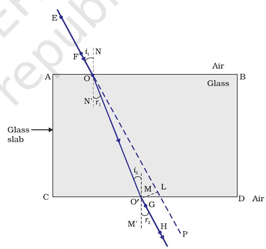
Figure 9.10 Refraction of light through a rectangular glass slab
Now you are familiar with the refraction of light. Refraction is due to change in the speed of light as it enters from one transparent medium to another. Experiments show that refraction of light occurs according to certain laws.
The following are the laws of refraction of light.
(i) The incident ray, the refracted ray and the normal to the interface of two transparent media at the point of incidence, all lie in the same plane.
(ii) The ratio of sine of angle of incidence to the sine of angle of refraction is a constant, for the light of a given colour and for the given pair of media. This law is also known as Snell’s law of refraction. (This is true for angle $0<i<90^{\circ}$ )If $i$ is the angle of incidence and $r$ is the angle of refraction, then,
$$ \begin{equation*} \dfrac{\sin i}{\sin r}=\text { constant } \tag{9.4} \end{equation*} $$
This constant value is called the refractive index of the second medium with respect to the first. Let us study about refractive index in some detail.
9.3.2 The Refractive Index
You have already studied that a ray of light that travels obliquely from one transparent medium into another will change its direction in the second medium. The extent of the change in direction that takes place in a given pair of media may be expressed in terms of the refractive index, the “constant” appearing on the right-hand side of Eq.(9.4).
The refractive index can be linked to an important physical quantity, the relative speed of propagation of light in different media. It turns out that light propagates with different speeds in different media. Light travels fastest in vacuum with speed of $3 \times 10^{8} m s^{-1}$. In air, the speed of light is only marginally less, compared to that in vacuum. It reduces considerably in glass or water. The value of the refractive index for a given pair of media depends upon the speed of light in the two media, as given below.
Consider a ray of light travelling from medium 1 into medium 2 , as shown in Fig.9.11. Let $v_1$ be the speed of light in medium 1 and $v_2$ be the speed of light in medium 2 . The refractive index of medium 2 with respect to medium 1 is given by the ratio of the speed of light in medium 1 and the speed of light in medium 2 . This is usually represented by the symbol $n _{21}$. This can be expressed in an equation form as
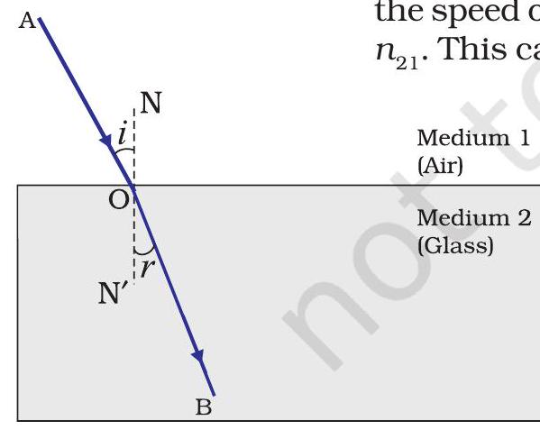
Figure 9.11
$$ \begin{equation*} n _{21}=\dfrac{\text { Speed of light in medium } 1 }{\text { Speed of light in medium } 2 }=\dfrac{v _{1}}{v _{2}} \tag{9.5} \end{equation*} $$
By the same argument, the refractive index of medium 1 with respect to medium 2 is represented as $n _{12}$. It is given by
$$ \begin{equation*} n _{12}=\dfrac{\text { Speed of light in medium } 2 }{\text { Speed of light in medium } 1 }=\dfrac{v _{2}}{v _{1}} \tag{9.6} \end{equation*} $$
If medium 1 is vacuum or air, then the refractive index of medium 2 is considered with respect to vacuum. This is called the absolute refractive index of the medium. It is simply represented as $n_2$. If $c$ is the speed of light in air and $v$ is the speed of light in the medium, then, the refractive index of the medium $n_m$ is given by
$$ \begin{equation*} \mathrm{n} _{\mathrm{m}}=\dfrac{\text { Speed of light in air }}{\text { Speed of light in the medium }}=\dfrac{c}{v} \tag{9.7} \end{equation*} $$
The absolute refractive index of a medium is simply called its refractive index. The refractive index of several media is given in Table 9.3. From the Table you can know that the refractive index of water, $n_w=1.33$. This means that the ratio of the speed of light in air and the speed of light in water is equal to 1.33. Similarly, the refractive index of crown glass, $n_g=1.52$. Such data are helpful in many places. However, you need not memorise the data.
Table 9.3 Absolute refractive index of some material media
| Material medium | Refractive index | Material medium | Refractive index |
|---|---|---|---|
| Air | 1.0003 | Canada Balsam | 1.53 |
| Ice Water | 1.31 | Rock salt | 1.54 |
| Alcohol Kerosene | 1.33 | Carbon disulphide | 1.63 |
| Fused quartz | 1.44 | Dense flint glass | 1.65 |
| Turpentine oil Benzene | 1.46 | Ruby | 1.71 |
| Crown glass | 1.50 | Sapphire | 1.77 |
Note from Table 9.3 that an optically denser medium may not possess greater mass density. For example, kerosene having higher refractive index, is optically denser than water, although its mass density is less than water.
Do you know?
The ability of a medium to refract light is also expressed in terms of its optical density. Optical density has a definite connotation. It is not the same as mass density. We have been using the terms ‘rarer medium’ and ‘denser medium’ in this Chapter. It actually means ‘optically rarer medium’ and ‘optically denser medium’, respectively. When can we say that a medium is optically denser than the other? In comparing two media, the one with the larger refractive index is optically denser medium than the other. The other medium of lower refractive index is optically rarer. The speed of light is higher in a rarer medium than a denser medium. Thus, a ray of light travelling from a rarer medium to a denser medium slows down and bends towards the normal. When it travels from a denser medium to a rarer medium, it speeds up and bends away from the normal.
Questions
1. A ray of light travelling in air enters obliquely into water. Does the light ray bend towards the normal or away from the normal? Why?
Show Answer
Answer
The light ray bends towards the normal.
When a ray of light travels from an optically rarer medium to an optically denser medium, it gets bent towards the normal. Since water is optically denser than air, a ray of light travelling from air into the water will bend towards the normal.
2. Light enters from air to glass having refractive index 1.50. What is the speed of light in the glass? The speed of light in vacuum is $3 \times 10^{8} m s^{-1}$.
Show Answer
Answer
Refractive index of a medium nm is given by,
$ n_m=\dfrac{\text{ Speed of light in vacuum }}{\text{ Speed of light in the medium }}=\dfrac{c}{v} $
Speed of light in vacuum, $c=3 \times 108 m s-1$
Refractive index of glass, $ng=1.50$
Speed of light in the glass,
$ v=\dfrac{c}{n_g}=\dfrac{3 \times 10^{8}}{1.50}=2 \times 10^{8} m s^{-1} $
3. Find out, from Table 9.3, the medium having highest optical density. Also find the medium with lowest optical density.
Show Answer
Answer
Material Refractive index Material medium Refractive
| medium | index | ||
|---|---|---|---|
| Air | 1.0003 | Canada Balsam | 1.53 |
| Ice | 1.31 | - | - |
| Water | 1.33 | Rock salt | 1.54 |
| Alcohol | 1.36 | - | - |
| Kerosene | 1.44 | Carbon disulphide | 1.63 |
| Fused | Dense | ||
| quartz | 1.46 | flint glass | 1.65 |
| Turpentine oil | 1.47 | Ruby | 1.71 |
| Benzene | 1.50 | Sapphire | 1.77 |
| Crown | 2.42 | ||
| glass | 1.52 | Diamond |
Highest optical density = Diamond
Lowest optical density $=$ Air
Optical density of a medium is directly related with the refractive index of that medium. A medium which has the highest refractive index will have the highest optical density and viceversa.
It can be observed from table 10.3 that diamond and air respectively have the highest and lowest refractive index. Therefore, diamond has the highest optical density and air has the lowest optical density.
4. You are given kerosene, turpentine and water. In which of these does the light travel fastest? Use the information given in Table 9.3.
Show Answer
Answer
Material Refractive indexMaterial medium Refractive
medium index
Air $\quad 1.0003$ Canada Balsam 1.53
| Ice | 1.31 | - | |
|---|---|---|---|
| Water | 1.33 | Rock salt | 1.54 |
| Alcohol | 1.36 | - | - |
| Kerosene | 1.44 | Carbon disulphide | 1.63 |
| Fused | |||
| quartz | 1.46 | Dense | |
| Turpentine oil | 1.47 | Ruby | 1.65 |
| Benzene | 1.50 | Sapphire | 1.71 |
| Crown | |||
| glass | 1.52 | Diamond | 2.42 |
Speed of light in a medium is given by the relation for refractive index (nm). The relation is given as
$ \begin{aligned} & n_m=\dfrac{\text{ Speed of light in air }}{\text{ Speed of light in the medium }}=\dfrac{c}{v} \\ & v=\dfrac{c}{n_m} \\ & v \propto \dfrac{1}{n_m} \end{aligned} $
It can be inferred from the relation that light will travel the slowest in the material which has the highest refractive index and travel the fastest in the material which has the lowest refractive index.
It can be observed from table 10.3 that the refractive indices of kerosene, turpentine, and water are 1.44, 1.47, and 1.33 respectively. Therefore, light travels the fastest in water.
5. The refractive index of diamond is 2.42. What is the meaning of this statement?
Show Answer
Answer
Refractive index of a medium $nm$ is related to the speed of light in that medium $v$ by the relation:
$ n_m=\dfrac{\text{ Speed of light in air }}{\text{ Speed of light in the medium }}=\dfrac{c}{v} $
Where, $c$ is the speed of light in vacuum/air
The refractive index of diamond is 2.42 . This suggests that the speed of light in diamond will reduce by a factor 2.42 compared to its speed in air.
9.3.3 Refraction by Spherical Lenses
You might have seen watchmakers using a small magnifying glass to see tiny parts. Have you ever touched the surface of a magnifying glass with your hand? Is it plane surface or curved? Is it thicker in the middle or at the edges? The glasses used in spectacles and that by a watchmaker are examples of lenses. What is a lens? How does it bend light rays? We shall discuss these in this section.

(a)

(b)
Figure 9.12 (a) Converging action of a convex lens, (b) diverging action of a concave lens
A transparent material bound by two surfaces, of which one or surfaces are spherical, forms a lens. This means that a lens is bound by at least one spherical surface. In such lenses, the other surface would be plane. A lens may have two spherical surfaces, bulging outwards. Such a lens is called a double convex lens. It is simply called a convex lens. It is thicker at the middle as compared to the edges. Convex lens converges light rays as shown in Fig. 9.12 (a).
Hence convex lenses are also called converging lenses. Similarly, a double concave lens is bounded by two spherical surfaces, curved inwards. It is thicker at the edges than at the middle. Such lenses diverge light rays as shown in Fig. 9.12 (b). Such lenses are also called diverging lenses. A double concave lens is simply called a concave lens.
A lens, either a convex lens or a concave lens, has two spherical surfaces. Each of these surfaces forms a part of a sphere. The centres of these spheres are called centres of curvature of the lens. The centre of curvature of a lens is usually represented by the letter $C$. Since there are two centres of curvature, we may represent them as $C_1$ and $C_2$. An imaginary straight line passing through the two centres of curvature of a lens is called its principal axis. The central point of a lens is its optical centre. It is usually represented by the letter $O$.
A ray of light through the optical centre of a lens passes without suffering any deviation. The effective diameter of the circular outline of a spherical lens is called its aperture. We shall confine our discussion in this Chapter to such lenses whose aperture is much less than its radius of curvature and the two centres of curvatures are equidistant from the optical centre O. Such lenses are called thin lenses with small apertures. What happens when parallel rays of light are incident on a lens? Let us do an Activity to understand this.
Activity 9.11
CAUTION: Do not look at the Sun directly or through a lens while doing this Activity or otherwise. You may damage your eyes if you do so.
- Hold a convex lens in your hand. Direct it towards the Sun.
- Focus the light from the Sun on a sheet of paper. Obtain a sharp bright image of the Sun.
- Hold the paper and the lens in the same position for a while. Keep observing the paper. What happened? Why? Recall your experience in Activity 9.2.
The paper begins to burn producing smoke. It may even catch fire after a while. Why does this happen? The light from the Sun constitutes parallel rays of light. These rays were converged by the lens at the sharp bright spot formed on the paper. In fact, the bright spot you got on the paper is a real image of the Sun. The concentration of the sunlight at a point generated heat. This caused the paper to burn.
Now, we shall consider rays of light parallel to the principal axis of a lens. What happens when you pass such rays of light through a lens? This is illustrated for a convex lens in Fig. 9.12 (a) and for a concave lens in Fig.9.12 (b).
Observe Fig.9.12 (a) carefully. Several rays of light parallel to the principal axis are falling on a convex lens. These rays, after refraction from the lens, are converging to a point on the principal axis. This point on the principal axis is called the principal focus of the lens. Let us see now the action of a concave lens.
Observe Fig.9.12 (b) carefully. Several rays of light parallel to the principal axis are falling on a concave lens. These rays, after refraction from the lens, are appearing to diverge from a point on the principal axis. This point on the principal axis is called the principal focus of the concave lens.
If you pass parallel rays from the opposite surface of the lens, you get another principal focus on the opposite side. Letter $F$ is usually used to represent principal focus. However, a lens has two principal foci. They are represented by $F_1$ and $F_2$. The distance of the principal focus from the optical centre of a lens is called its focal length. The letter $f$ is used to represent the focal length. How can you find the focal length of a convex lens? Recall the Activity 9.11. In this Activity, the distance between the position of the lens and the position of the image of the Sun gives the approximate focal length of the lens.
9.3.4 Image Formation by Lenses
Lenses form images by refracting light. How do lenses form images? What is their nature? Let us study this for a convex lens first.
Activity 9.12
- Take a convex lens. Find its approximate focal length in a way described in Activity 9.11.
- Draw five parallel straight lines, using chalk, on a long Table such that the distance between the successive lines is equal to the focal length of the lens.
- Place the lens on a lens stand. Place it on the central line such that the optical centre of the lens lies just over the line.
- The two lines on either side of the lens correspond to $F$ and $2 F$ of the lens respectively. Mark them with appropriate letters such as $2 F_1, F_1, F_2$ and $2 F_2$, respectively.
- Place a burning candle, far beyond $2 F_1$ to the left. Obtain a clear sharp image on a screen on the opposite side of the lens.
- Note down the nature, position and relative size of the image.
- Repeat this Activity by placing object just behind $2 F_1$, between $F_1$ and $2 F_1$ at $F_1$, between $F_1$ and $O$. Note down and tabulate your observations.
The nature, position and relative size of the image formed by convex lens for various positions of the object is summarised in Table 9.4.
Table 9.4 Nature, position and relative size of the image formed by a convex lens for various positions of the object
| Position of the object | Position of the image | Relative size of the image | Nature of the image |
|---|---|---|---|
| At infinity | At focus $F_2$ | Highly diminished, point-sized | Real and inverted |
| Beyond $2 F_1$ | Between $F_2$ and $2 F_2$ | Diminished | Real and inverted |
| At $2 F_1$ | At $2 F_2$ | Same size | Real and inverted |
| Between $F_1$ and | Beyond $2 F_2$ | Enlarged | Real and inverted |
| At focus $F_1$ | At infinity | Infinitely large or highly enlarged | Real and inverted |
| Between focus $F_1$ and optical centre $O$ | On the same side of the lens as the object | Enlarged | Virtual and erect |
Let us now do an Activity to study the nature, position and relative size of the image formed by a concave lens.
Activity 9.13
- Take a concave lens. Place it on a lens stand.
- Place a burning candle on one side of the lens.
- Look through the lens from the other side and observe the image. Try to get the image on a screen, if possible. If not, observe the image directly through the lens.
- Note down the nature, relative size and approximate position of the image.
- Move the candle away from the lens. Note the change in the size of the image. What happens to the size of the image when the candle is placed too far away from the lens.
The summary of the above Activity is given in Table 9.5 below.
Table 9.5 Nature, position and relative size of the image formed by a concave lens for various positions of the object
| Position of the object | Position of the image | Relative size of the image | Nature of the image |
|---|---|---|---|
| At infinity | At focus $F_1$ | Highly diminished, point-sized | Virtual and erect |
| Between infinity and optical centre $O$ of the lens | Between focus $F_1$ and optical centre $O$ | Diminished | Virtual and erect |
What conclusion can you draw from this Activity? A concave lens will always give a virtual, erect and diminished image, irrespective of the position of the object.
9.3.5 Image Formation in Lenses Using Ray Diagrams
We can represent image formation by lenses using ray diagrams. Ray diagrams will also help us to study the nature, position and relative size of the image formed by lenses. For drawing ray diagrams in lenses, alike of spherical mirrors, we consider any two of the following rays -
(i) A ray of light from the object, parallel to the principal axis, after refraction from a convex lens, passes through the principal focus on the other side of the lens, as shown in Fig. 9.13 (a). In case of a concave lens, the ray appears to diverge from the principal focus located on the same side of the lens, as shown in Fig. 9.13 (b).

(ii) A ray of light passing through a principal focus, after refraction from a convex lens, will emerge parallel to the principal axis. This is shown in Fig. 9.14 (a). A ray of light appearing to meet at the principal focus of a concave lens, after refraction, will emerge parallel to the principal axis. This is shown in Fig.9.14 (b).

(iii) A ray of light passing through the optical centre of a lens will emerge without any deviation. This is illustrated in Fig.9.15(a) and Fig.9.15 (b).

The ray diagrams for the image formation in a convex lens for a few positions of the object are shown in Fig. 9.16. The ray diagrams representing the image formation in a concave lens for various positions of the object are shown in Fig. 9.17.

Figure 9.16 The position, size and the nature of the image formed by a convex lens for various positions of the object

Figure 9.17 Nature, position and relative size of the image formed by a concave lens
9.3.6 Sign Convention for Spherical Lenses
For lenses, we follow sign convention, similar to the one used for spherical mirrors. We apply the rules for signs of distances, except that all measurements are taken from the optical centre of the lens. According to the convention, the focal length of a convex lens is positive and that of a concave lens is negative. You must take care to apply appropriate signs for the values of $u, v, f$, object height $h$ and image height $h^{\prime}$.
9.3.7 Lens Formula and Magnification
As we have a formula for spherical mirrors, we also have formula for spherical lenses. This formula gives the relationship between objectdistance $(u)$, image-distance $(v)$ and the focal length $(f)$. The lens formula is expressed as
$$ \begin{equation*} \dfrac{1}{v}-\dfrac{1}{u}=\dfrac{1}{f} \tag{9.8} \end{equation*} $$
The lens formula given above is general and is valid in all situations for any spherical lens. Take proper care of the signs of different quantities, while putting numerical values for solving problems relating to lenses.
Magnification
The magnification produced by a lens, similar to that for spherical mirrors, is defined as the ratio of the height of the image and the height of the object. Magnification is represented by the letter $m$. If $h$ is the height of the object and $h^{\prime}$ is the height of the image given by a lens, then the magnification produced by the lens is given by,
$$ \begin{equation*} m=\dfrac{\text { Height of the Image }}{\text { Height of the object }}=\dfrac{h^{\prime}}{h} \tag{9.9} \end{equation*} $$
Magnification produced by a lens is also related to the object-distance $u$, and the image-distance $v$. This relationship is given by
Magnification $(m)=\dfrac{h}{h}=\dfrac{v}{u}$
Example 9.3
A concave lens has focal length of $15 cm$. At what distance should the object from the lens be placed so that it forms an image at $10 cm$ from the lens? Also, find the magnification produced by the lens.
Solution
A concave lens always forms a virtual, erect image on the same side of the object.
Image-distance $v=-10 cm$;
Focal length $f \quad=-15 cm$;
Object-distance $u=$ ?
Since $\dfrac{1}{v}-\dfrac{1}{u}=\dfrac{1}{f}$
or, $\dfrac{1}{u}=\dfrac{1}{v}-\dfrac{1}{f}$
$ \dfrac{1}{u}=\dfrac{1}{-10}-\dfrac{1}{(-15)}=-\dfrac{1}{10}+\dfrac{1}{15} $
$\dfrac{1}{u}=\dfrac{-3+2}{30}=\dfrac{1}{-30}$
or, $\quad u=-30 cm$
Thus, the object-distance is $30 cm$.
Magnification $m=v / u$
$ m=\dfrac{-10 cm}{-30 cm}=\dfrac{1}{3} ;+0.33 $
The positive sign shows that the image is erect and virtual. The image is one-third of the size of the object.
Example 9.4
A $2.0 cm$ tall object is placed perpendicular to the principal axis of a convex lens of focal length $10 cm$. The distance of the object from the lens is $15 cm$. Find the nature, position and size of the image. Also find its magnification.
Solution
Height of the object $h=+2.0 \mathrm{~cm}$;
Focal length $f=+10 \mathrm{~cm}$;
object-distance $u=-15 \mathrm{~cm}$;
Image-distance $v=$ ?
Height of the image $h^{\prime}=$ ?
Since $\dfrac{1}{v}-\dfrac{1}{u}=\dfrac{1}{f}$
or, $\dfrac{1}{v}=\dfrac{1}{u}+\dfrac{1}{f}$
$\dfrac{1}{v}=\dfrac{1}{(-15)}+\dfrac{1}{10}=-\dfrac{1}{15}+\dfrac{1}{10}$
$\dfrac{1}{v}=\dfrac{-2+3}{30}=\dfrac{1}{30}$
or, $v=+30 \mathrm{~cm}$
The positive sign of $v$ shows that the image is formed at a distance of $30 cm$ on the other side of the optical centre. The image is real and inverted.
Magnification $m=\dfrac{h^{\prime}}{h}=\dfrac{v}{u}$
or, $\quad h^{\prime}=h(v / u)$
Height of the image, $h^{\prime}=(2.0)(+30 /-15)=-4.0 cm$
Magnification $m=v / u$
or, $m=\dfrac{+30 cm}{-15 cm}=-2$
The negative signs of $m$ and $h^{\prime}$ show that the image is inverted and real. It is formed below the principal axis. Thus, a real, inverted image, $4 cm$ tall, is formed at a distance of $30 cm$ on the other side of the lens. The image is two times enlarged.
9.3.8 Power of a Lens
You have already learnt that the ability of a lens to converge or diverge light rays depends on its focal length. For example, a convex lens of short focal length bends the light rays through large angles, by focussing them closer to the optical centre. Similarly, concave lens of very short focal length causes higher divergence than the one with longer focal length. The degree of convergence or divergence of light rays achieved by a lens is expressed in terms of its power. The power of a lens is defined as the reciprocal of its focal length. It is represented by the letter $P$. The power $P$ of a lens of focal length $f$ is given by
$$ \begin{equation*} \mathrm{P}=\dfrac{1}{f} \tag{9.11} \end{equation*} $$
The SI unit of power of a lens is ‘dioptre’. It is denoted by the letter D. If $f$ is expressed in metres, then, power is expressed in dioptres. Thus, 1 dioptre is the power of a lens whose focal length is 1 metre. $1 D=1 m^{-1}$. You may note that the power of a convex lens is positive and that of a concave lens is negative.
Opticians prescribe corrective lenses indicating their powers. Let us say the lens prescribed has power equal to $+2.0 D$. This means the lens prescribed is convex. The focal length of the lens is $+0.50 m$. Similarly, a lens of power $-2.5 D$ has a focal length of $-0.40 m$. The lens is concave.
More to know!
Many optical instruments consist of a number of lenses. They are combined to increase the magnification and sharpness of the image. The net power (P ) of the lenses placed in contact is given by the algebraic sum of the individual powers $ P_1, P_2, P_3,$ … as $P = P_1 + P_2 + P_3 + …$ The use of powers, instead of focal lengths, for lenses is quite convenient for opticians.During eye-testing, an optician puts several different combinations of corrective lenses of known power, in contact, inside the testing spectacles’ frame. The optician calculates the power of the lens required by simple algebraic addition. For example, a combination of two lenses of power + 2.0 D and + 0.25 D is equivalent to a single lens of power + 2.25 D. The simple additive property of the powers of lenses can be used to design lens systems to minimise certain defects in images produced by a single lens. Such a lens system, consisting of several lenses, in contact, is commonly used in the design of lenses of camera, microscopes and telescopes.
QUESTIONS
1. Define 1 dioptre of power of a lens.
Show Answer
#missing2. A convex lens forms a real and inverted image of a needle at a distance of 50 cm from it. Where is the needle placed in front of the convex lens if the image is equal to the size of the object? Also, find the power of the lens.
Show Answer
#missing3. Find the power of a concave lens of focal length 2 m.
Show Answer
#missingWhat you have learnt
- Light seems to travel in straight lines.
- Mirrors and lenses form images of objects. Images can be either real or virtual, depending on the position of the object.
- The reflecting surfaces, of all types, obey the laws of reflection. The refracting surfaces obey the laws of refraction.
- New Cartesian Sign Conventions are followed for spherical mirrors and lenses.
- Mirror formula, $\dfrac{1}{v}+\dfrac{1}{u}=\dfrac{1}{f}$, gives the relationship between the object-distance $(u)$, image-distance $(v)$, and focal length $(f)$ of a spherical mirror.
- The focal length of a spherical mirror is equal to half its radius of curvature.
- The magnification produced by a spherical mirror is the ratio of the height of the image to the height of the object.
- A light ray travelling obliquely from a denser medium to a rarer medium bends away from the normal. A light ray bends towards the normal when it travels obliquely from a rarer to a denser medium.
- Light travels in vacuum with an enormous speed of $3 \times 10^{8} m s^{-1}$. The speed of light is different in different media.
- The refractive index of a transparent medium is the ratio of the speed of light in vacuum to that in the medium.
- In case of a rectangular glass slab, the refraction takes place at both air-glass interface and glass-air interface. The emergent ray is parallel to the direction of incident ray.
- Lens formula, $\dfrac{1}{v}-\dfrac{1}{u}=\dfrac{1}{f}$, gives the relationship between the object-distance $(u)$, image-distance $(v)$, and the focal length $(f)$ of a spherical lens.
- Power of a lens is the reciprocal of its focal length. The SI unit of power of a lens is dioptre.
EXERCISES
1. Which one of the following materials cannot be used to make a lens?
(a) Water
(b) Glass
(c) Plastic
(d) Clay
Show Answer
Answer
(d) A lens allows light to pass through it. Since clay does not show such property, it cannot be used to make a lens.
2. The image formed by a concave mirror is observed to be virtual, erect and larger than the object. Where should be the position of the object?
(a) Between the principal focus and the centre of curvature
(b) At the centre of curvature
(c) Beyond the centre of curvature
(d) Between the pole of the mirror and its principal focus.
Show Answer
Answer
(d) Between the pole of the mirror and its principal focus
3. Where should an object be placed in front of a convex lens to get a real image of the size of the object?
(a) At the principal focus of the lens
(b) At twice the focal length
(c) At infinity
(d) Between the optical centre of the lens and its principal focus.
Show Answer
Answer
(b) When an object is placed at the centre of curvature in front of a convex lens, its image is formed at the centre of curvature on the other side of the lens. The image formed is real, inverted, and of the same size as the object.
4. A spherical mirror and a thin spherical lens have each a focal length of $-15 cm$. The mirror and the lens are likely to be
(a) both concave.
(b) both convex.
(c) the mirror is concave and the lens is convex.
(d) the mirror is convex, but the lens is concave.
Show Answer
Answer
(a) By convention, the focal length of a concave mirror and a concave lens are taken as negative. Hence, both the spherical mirror and the thin spherical lens are concave in nature.
5. No matter how far you stand from a mirror, your image appears erect. The mirror is likely to be
(a) only plane.
(b) only concave.
(c) only convex.
(d) either plane or convex.
Show Answer
Answer
(d) A convex mirror always gives a virtual and erect image of smaller size of the object placed in front of it. Similarly, a plane mirror will always give a virtual and erect image of same size as that of the object placed in front of it. Therefore, the given mirror could be either plane or convex.
6. Which of the following lenses would you prefer to use while reading small letters found in a dictionary?
(a) A convex lens of focal length $50 cm$.
(b) A concave lens of focal length $50 cm$.
(c) A convex lens of focal length $5 cm$.
(d) A concave lens of focal length $5 cm$.
Show Answer
Answer
(c) A convex lens gives a magnified image of an object when it is placed between the radius of curvature and focal length. Also, magnification is more for convex lenses having shorter focal length. Therefore, for reading small letters, a convex lens of focal length $5 cm$ should be used.
7. We wish to obtain an erect image of an object, using a concave mirror of focal length $15 cm$. What should be the range of distance of the object from the mirror? What is the nature of the image? Is the image larger or smaller than the object? Draw a ray diagram to show the image formation in this case.
Show Answer
Answer
Range of object distance $=0 cm$ to $15 cm$
A concave mirror gives an erect image when an object is placed between its pole $(P)$ and the principal focus (F).
Hence, to obtain an erect image of an object from a concave mirror of focal length $15 cm$, the object must be placed anywhere between the pole and the focus. The image formed will be virtual, erect, and magnified in nature, as shown in the given figure.
8. Name the type of mirror used in the following situations.
(a) Headlights of a car.
(b) Side/rear-view mirror of a vehicle.
(c) Solar furnace.Support your answer with reason.
Show Answer
Answer
(a) Concave (b) Convex (c) Concave
Explanation:
(a) Concave mirror is used in the headlights of a car. This is because concave mirrors can produce powerful parallel beam of light when the light source is placed at their principal focus.
(b) Convex mirror is used in side/rear view mirror of a vehicle. Convex mirrors give a virtual, erect, and diminished image of the objects placed in front of it. Because of this, they have a wide field of view. It enables the driver to see most of the traffic behind him/her.
(c) Concave mirrors are convergent mirrors. That is why they are used to construct solar furnaces. Concave mirrors converge the light incident on them at a single point known as principal focus. Hence, they can be used to produce a large amount of heat at that point.
9. One-half of a convex lens is covered with a black paper. Will this lens produce a complete image of the object? Verify your answer experimentally. Explain your observations.
Show Answer
Answer
The convex lens will form complete image of an object, even if its one half is covered with black paper. It can be understood by the following two cases.
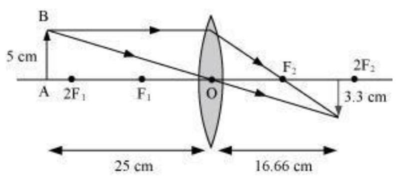
10. An object $5 cm$ in length is held $25 cm$ away from a converging lens of focal length $10 cm$. Draw the ray diagram and find the position, size and the nature of the image formed.
Show Answer
Answer
Object distance, $u=-25 cm$
Object height, ho $=5 cm$
Focal length, $f=+10 cm$
According to the lens formula,
$\dfrac{1}{v}-\dfrac{1}{u}=\dfrac{1}{f}$
$\dfrac{1}{v}=\dfrac{1}{f}+\dfrac{1}{u}=\dfrac{1}{10}-\dfrac{1}{25}=\dfrac{15}{250}$
$v=\dfrac{250}{15}=16.66 cm$
The positive value of $v$ shows that the image is formed at the other side of the lens.
Magnification, $m=-\dfrac{\text{ Image distance }}{\text{ Object distance }}=-\dfrac{v}{u}=\dfrac{-16.66}{25}=-0.66$
The negative sign shows that the image is real and formed behind the lens.
Magnification, $m=\dfrac{\text{ Image height }}{\text{ Object height }}=\dfrac{H_1}{H_0}=\dfrac{H_1}{5}$
$H_1=m \times H_0=-0.66 \times 5=-3.3 cm$
The negative value of image height indicates that the image formed is inverted.
The position, size, and nature of image are shown in the following ray diagram.
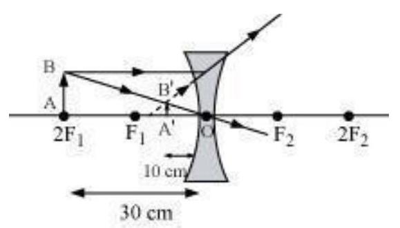
11. A concave lens of focal length $15 cm$ forms an image $10 cm$ from the lens. How far is the object placed from the lens? Draw the ray diagram.
Show Answer
Answer
Focal length of concave lens (OF1), $f=-15 cm$
Image distance, $v=-10 cm$
According to the lens formula,
$ \begin{aligned} & \dfrac{1}{v}-\dfrac{1}{u}=\dfrac{1}{f} \\ & \dfrac{1}{u}=\dfrac{1}{v}-\dfrac{1}{f}=\dfrac{-1}{10}-\dfrac{1}{(-15)}=\dfrac{-1}{10}+\dfrac{1}{15}=\dfrac{-5}{150} \\ & u=-30 cm \end{aligned} $
The negative value of $u$ indicates that the object is placed $30 cm$ in front of the lens. This is shown in the following ray diagram.
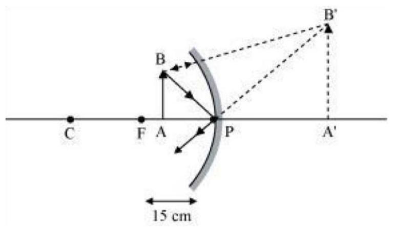
12. An object is placed at a distance of $10 cm$ from a convex mirror of focal length $15 cm$. Find the position and nature of the image.
Show Answer
Answer
Focal length of convex mirror, $f=+15 cm$
Object distance, $u=-10 cm$
According to the mirror formula,
$\dfrac{1}{v}+\dfrac{1}{u}=\dfrac{1}{f}$
$\dfrac{1}{v}=\dfrac{1}{f}-\dfrac{1}{u}=\dfrac{1}{15}+\dfrac{1}{10}=\dfrac{25}{150}$
$v=6 cm$
The positive value of $v$ indicates that the image is formed behind the mirror.
Magnification, $m=-\dfrac{\text{ Image distance }}{\text{ Object distance }}=-\dfrac{v}{u}=\dfrac{-6}{-10}=+0.6$
The positive value of magnification indicates that the image formed is virtual and erect.
13. The magnification produced by a plane mirror is +1 . What does this mean?
Show Answer
Answer
Magnification produced by a mirror is given by the relation
Magnification, $m=\dfrac{\text{ Image height }(H_1)}{\text{ Object height }(H_0)}$
The magnification produced by a plane mirror is +1 . It shows that the image formed by the plane mirror is of the same size as that of the object. The positive sign shows that the image formed is virtual and erect.
14. An object $5.0 cm$ in length is placed at a distance of $20 cm$ in front of a convex mirror of radius of curvature $30 cm$. Find the position of the image, its nature and size.
Show Answer
Answer
Object distance, $u=-20 cm$
Object height, $h=5 cm$
Radius of curvature, $R=30 cm$
Radius of curvature $=2 \times$ Focal length
$R=2 f$
$f=15 cm$
According to the mirror formula,
$\dfrac{1}{v}+\dfrac{1}{u}=\dfrac{1}{f}$
$\dfrac{1}{v}=\dfrac{1}{f}-\dfrac{1}{u}=\dfrac{1}{15}+\dfrac{1}{20}=\dfrac{4+3}{60}=\dfrac{7}{60}$
$v=8.57 cm$
The positive value of $v$ indicates that the image is formed behind the mirror.
Magnification, $m=-\dfrac{\text{ Image distance }}{\text{ Object distance }}=\dfrac{-8.57}{-20}=0.428$
The positive value of magnification indicates that the image formed is virtual.
Magnification, $m=\dfrac{\text{ Height of the image }}{\text{ Height of the object }}=\dfrac{h^{\prime}}{h}$
$h^{\prime}=m \times h=0.428 \times 5=2.14 cm$
The positive value of image height indicates that the image formed is erect.
Therefore, the image formed is virtual, erect, and smaller in size.
15. An object of size $7.0 cm$ is placed at $27 cm$ in front of a concave mirror of focal length $18 cm$. At what distance from the mirror should a screen be placed, so that a sharp focussed image can be obtained? Find the size and the nature of the image.
Show Answer
Answer
Object distance, $u=-27 cm$
Object height, $h=7 cm$
Focal length, $f=-18 cm$
According to the mirror formula,
$\dfrac{1}{u}+\dfrac{1}{v}=\dfrac{1}{f}$ $\dfrac{1}{v}=\dfrac{1}{f}-\dfrac{1}{u}=\dfrac{-1}{18}+\dfrac{1}{27}=\dfrac{-1}{54}$
$v=-54 cm$
The screen should be placed at a distance of $54 cm$ in front of the given mirror.
Magnification, $m=-\dfrac{\text{ Image distance }}{\text{ Object distance }}=\dfrac{-54}{27}=-2$
The negative value of magnification indicates that the image formed is real.
Magnification, $m=\dfrac{\text{ Height of the image }}{\text{ Height of the object }}=\dfrac{h^{\prime}}{h}$
$h^{\prime}=7 \times(-2)=-14 cm$
The negative value of image height indicates that the image formed is inverted.
16. Find the focal length of a lens of power $-2.0 D$. What type of lens is this?
Show Answer
Answer
A concave lens has a negative focal length. Hence, it is a concave lens.
17. A doctor has prescribed a corrective lens of power $+1.5 D$. Find the focal length of the lens. Is the prescribed lens diverging or converging?
Show Answer
Answer
A convex lens has a positive focal length. Hence, it is a convex lens or a converging lens.
हम इस संसार में अपने चारों ओर अनेक प्रकार की वस्तुएँ देखते हैं। तथापि, किसी अँधेरे कमरे में हम कुछ भी देखने में असमर्थ हैं। कमरे को प्रकाशित करने पर चीजें दिखलाई देने लगती हैं। वह क्या है जो वस्तुओं को दृश्यमान बनाता है। दिन के समय सूर्य का प्रकाश वस्तुओं को देखने में हमारी सहायता करता है। कोई वस्तु उस पर पड़ने वाले प्रकाश को परावर्तित करती है। यह परावर्तित प्रकाश जब हमारी आँखों द्वारा ग्रहण किया जाता है, तो हमें वस्तुओं को देखने योग्य बनाता है। हम किसी पारदर्शी माध्यम के आर-पार देख सकते हैं, क्योंकि प्रकाश इसमें से पार (transmitted) हो जाता है। प्रकाश से संबद्ध अनेक सामान्य तथा अद्दुत परिघटनाएँ हैं; जैसेदर्पणों द्वारा प्रतिबिंब का बनना, तारों का टिमटिमाना, इंद्रधनुष के सुंदर रंग, किसी माध्यम द्वारा प्रकाश को मोड़ना आदि। प्रकाश के गुणों का अध्ययन इनके अन्वेषण में हमारी सहायता करेगा।
अपने चारों ओर कुछ सामान्य प्रकाशिक परिघटनाओं को देख कर हम यह निष्कर्ष निकाल सकते हैं कि प्रकाश सरल रेखाओं में गमन करता प्रतीत होता है। यह तथ्य कि एक छोटा प्रकाश स्रोत किसी अपारदर्शी वस्तु की तीक्ष्ण छाया बनाता है, प्रकाश के एक सरलरेखीय पथ की ओर इंगित करता है, जिसे प्रायः प्रकाश किरण कहते हैं।
यह भी जानिया!
यदि प्रकाश के पथ में रखी अपारदर्शी वस्तु अत्यंत छोटी हो तो प्रकाश सरल रेखा में चलने की बजाय इसके किनारों पर मुड़ने की प्रवृत्ति दर्शाता है- इस प्रभाव को प्रकाश का विवर्तन कहते हैं। तब वह प्रकाशिकी, जिसमें सरलरेखीय व्यवहार के आधार पर किरणों का उपयोग करते हैं, असफल होने लगती हैं। विवर्तन जैसी परिघटनाओं की व्याख्या करने के लिए प्रकाश को तरंग के रूप में माना जाता है, जिसका विस्तृत अध्ययन आप उच्च कक्षाओं में करेंगे। पुन: 20 वीं शताब्दी के प्रारंभ में यह स्पष्ट हो गया कि प्रकाश की द्रव्य के साथ अन्योन्यक्रिया के विवेचन में प्रकाश का तरंग सिद्धांत अपर्याप्त है तथा प्रकाश प्रायः कणों के प्रवाह की भाँति व्यवहार करता है। प्रकाश की सही प्रकृति के बारे में यह उलझन कुछ वर्षों तक चलती रही जब तक कि प्रकाश का आधुनिक क्वांटम सिद्धांत उभर कर सामने नहीं आया, जिसमें प्रकाश को न तो ‘तरंग’ माना गया न ही ‘कण’। इस नए सिद्धांत ने प्रकाश के कण संबंधी गुणों तथा तरंग प्रकृति के बीच सामंजस्य स्थापित किया।
इस अध्याय में हम प्रकाश के परावर्तन तथा अपवर्तन की परिघटनाओं का, प्रकाश के सरलेखीय गमन का उपयोग करके, अध्ययन करेंगे। ये मूल धारणाएँ प्रकृति में घटनेवाली कुछ प्रकाशिक परिघटनाओं के अध्ययन में हमारी सहायता करेंगी। इस अध्याय में हम गोलीय दर्पणों द्वारा प्रकाश के परावर्तन, प्रकाश के अपवर्तन एवं वास्तविक जीवन में उनके अनुप्रयोगों को समझने का प्रयत्न करेंगे।
9.1 प्रकाश का परावर्तन
उच्च कोटि की पॉलिश किया हुआ पृष्ठ, जैसे कि दर्पण, अपने पर पड़नेवाले अधिकांश प्रकाश को परावर्तित कर देता है। आप प्रकाश के परावर्तन के नियमों से पहले से ही परिचित हैं।
आइए, इन नियमों को स्मरण करें-
(i) आपतन कोण, परावर्तन कोण के बराबर होता है, तथा
(ii) आपतित किरण, दर्पण के आपतन बिंदु पर अभिलंब तथा परावर्तित किरण, सभी एक ही तल में होते हैं।
परावर्तन के ये नियम गोलीय पृष्ठों सहित सभी प्रकार के परावर्तक पृष्ठों के लिए लागू होते हैं। आप समतल दर्पण द्वारा प्रतिबिंब के बनने से परिचित हैं। प्रतिबिंब की क्या विशेषताएँ हैं? समतल दर्पण द्वारा बना प्रतिबिंब सदैव आभासी तथा सीधा होता है। प्रतिबिंब का साइज़ बिंब (वस्तु) के साइज़ के बराबर होता है। प्रतिबिंब दर्पण के पीछे उतनी ही दूरी पर बनता है, जितनी दूरी पर दर्पण के सामने बिंब रखा होता है। इसके अतिरिक्त प्रतिबिंब पार्श्व परिवर्तित होता है। यदि परावर्तक पृष्ठ वक्रित हों तो प्रतिबिंब कैसे बनेंगे? आइए देखें।
क्रियाकलाप 9.1
- एक बड़ी चमकदार चम्मच लीजिए। इसके वक्रित पृष्ठ में अपना चेहरा देखने का प्रयत्न कीजिए।
- क्या आप प्रतिबिंब देख पाते हैं? यह छोटा है या बड़ा?
- चम्मच को धीरे-धीरे अपने चेहरे से दूर ले जाइए। प्रतिबिंब को देखते रहिए। यह कैसे परिवर्तित होता है?
- चम्मच को उलटा कीजिए (पलटिए) तथा दूसरे पृष्ठ से क्रियाकलाप को दोहराइए। अब प्रतिबिंब कैसा दिखलाई देता है?
- दोनों पृष्ठों पर प्रतिबिंब के अभिलक्षणों की तुलना कीजिए।
चमकदार चम्मच का वक्रित पृष्ठ एक वक्रित दर्पण की भाँति माना जा सकता है। सबसे अधिक उपयोग में आने वाले सामान्यतः वक्रित दर्पण का प्रारूप गोलीय दर्पण है। इस प्रकार के दर्पणों के परावर्तक पृष्ठ किसी गोले के पृष्ठ का एक भाग माना जा सकता है। ऐसे दर्पण जिनका परावर्तक पृष्ठ गोलीय है, गोलीय दर्पण कहलाते हैं। अब हम गोलीय दर्पणों के बारे में कुछ विस्तार से अध्ययन करेंगे।
9.2 गोलीय दर्पण
गोलीय दर्पण का परावर्तक पृष्ठ अंदर की ओर या बाहर की ओर वक्रित हो सकता है। गोलीय दर्पण, जिसका परावर्तक पृष्ठ अंदर की ओर अर्थात गोले के केंद्र की ओर वक्रित है, वह अवतल दर्पण कहलाता है। वह गोलीय दर्पण जिसका परावर्तक पृष्ठ बाहर की ओर वक्रित है, उत्तल दर्पण कहलाता है। इन दर्पणों का आरेखीय निरूपण चित्र 9.1 में किया गया है। इन चित्रों में नोट कीजिए कि दर्पणों का पृष्ठभाग छायांकित है।
अब आप समझ सकते हैं कि चम्मच का अंदर की ओर वक्रित पृष्ठ लगभग अवतल दर्पण जैसा है तथा चम्मच का बाहर की ओर उभरा पृष्ठ लगभग उत्तल दर्पण जैसा है।
गोलीय दर्पणों के बारे में और अधिक ज्ञान प्राप्त करने से पहले आइए हम कुछ शब्दों अथवा पदों (terms) को जानें तथा उनका अर्थ समझें। ये शब्द गोलीय दर्पणों के बारे में चर्चा करते समय सामान्यतः प्रयोग में आते हैं। गोलीय दर्पण के परावर्तक पृष्ठ के केंद्र को दर्पण का ध्रुव कहते हैं। यह दर्पण के पृष्ठ पर स्थित होता है। ध्रुव को प्रायः $\mathrm{P}$ अक्षर से निरूपित करते हैं।

चित्र 9.1 गोलीय दर्पणों का आरेखीय निरूपण; छायांकित भाग परावर्तक नहीं है।
गोलीय दर्पण का परावर्तक पृष्ठ एक गोले का भाग है। इस गोले का केंद्र गोलीय दर्पण का वक्रता केंद्र कहलाता है। यह अक्षर $\mathrm{C}$ से निरूपित किया जाता है। कृपया ध्यान दें कि वक्रता केंद्र दर्पण का भाग नहीं है। यह परावर्तक पृष्ठ के बाहर स्थित है। अवतल दर्पण का वक्रता केंद्र परावर्तक पृष्ठ के सामने स्थित होता है। तथापि, उत्तल दर्पण में यह दर्पण के परावर्तक पृष्ठ के पीछे स्थित होता है। यह तथ्य आप चित्र 9.2 (a) तथा 9.2 (b) में नोट कर सकते हैं। गोलीय दर्पण का परावर्तक पृष्ठ जिस गोले का भाग है, उसकी त्रिज्या दर्पण की वक्रता त्रिज्या कहलाती है। इसे अक्षर $\mathrm{R}$ से निरूपित किया जाता है। ध्यान दीजिए कि PC दूरी वक्रता त्रिज्या के बराबर है। गोलीय दर्पण के ध्रुव तथा वक्रता त्रिज्या से गुज़रने वाली एक सीधी रेखा की कल्पना कीजिए। इस रेखा को दर्पण का मुख्य अक्ष कहते हैं। याद कीजिए कि मुख्य अक्ष दर्पण के ध्रुव पर अभिलंब है। आइए, दर्पण से संबंधित एक महत्वपूर्ण शब्द को एक क्रियाकलाप द्वारा समझें।
क्रियाकलाप 9.2
चेतावनी— सूर्य की ओर या दर्पण द्वारा परावर्तित सूर्य के प्रकाश की ओर सीधा मत देखिए। यह आपकी आँखों को क्षतिग्रस्त कर सकता है।
- एक अवतल दर्पण को अपने हाथ में पकड़िए तथा इसके परावर्तक पृष्ठ को सूर्य की ओर कीजिए।
- दर्पण द्वारा परावर्तित प्रकाश को दर्पण के पास रखी एक कागज़ की शीट पर डालिए।
- कागज़ की शीट को धीरे-धीरे आगे पीछे कीजिए जब तक कि आपको कागज़ की शीट पर प्रकाश का एक चमकदार, तीक्ष्ण बिंदु प्राप्त न हो जाए।
- दर्पण तथा कागज़ को कुछ मिनट के लिए उसी स्थिति में पकड़े रखिए। आप क्या देखते हैं? ऐसा क्यों होता है?
सर्वप्रथम कागज़ सुलगना प्रारंभ करता है और धुआँ उठने लगता है। अंततः यह आग भी पकड़ सकता है। यह क्यों जलता है? सूर्य से आने वाला प्रकाश दर्पण के द्वारा एक तीक्ष्ण, चमकदार बिंदु के रूप में अभिकेंद्रित होता है। वास्तव में कागज़ की शीट पर प्रकाश का यह बिंदु सूर्य का प्रतिबिंब है। यह बिंदु अवतल दर्पण का फोकस है। सूर्य के प्रकाश के संकेंद्रण से उत्पन्न ऊष्मा के कारण कागज़ जलता है। दर्पण की स्थिति से इस प्रतिबिंब की दूरी, दर्पण की फोकस दूरी का सन्निकट मान है।
(a)
(b)
चित्र 9.2 (a) अवतल दर्पण (b) उत्तल दर्पण
आइए, इस प्रेक्षण को एक किरण आरेख से समझने का प्रयत्न करें।
चित्र 9.2 (a) को ध्यानपूर्वक देखिए। अवतल दर्पण पर मुख्य अक्ष के समांतर कुछ किरणें आपतित हो रही हैं। परावर्तित किरणों का प्रेक्षण कीजिए। वे सभी दर्पण की मुख्य अक्ष के एक बिंदु पर मिल रही प्रतिच्छेदी हैं। यह बिंदु अवतल दर्पण का मुख्य फोकस कहलाता है। इसी प्रकार चित्र 9.2 (b) को ध्यानपूर्वक देखिए। उत्तल दर्पण द्वारा मुख्य अक्ष के समांतर किरणें किस प्रकार परावर्तित होती हैं? परावर्तित किरणें मुख्य अक्ष पर एक बिंदु से आती हुई प्रतीत होती हैं। यह बिंदु उत्तल दर्पण का मुख्य फोकस कहलाता है। मुख्य फोकस को अक्षर $F$ द्वारा निरूपित किया जाता है। गोलीय दर्पण के ध्रुव तथा मुख्य फोकस के बीच की दूरी फोकस दूरी कहलाती है। इसे अक्षर $f$ द्वारा निरूपित करते हैं।
गोलीय दर्पण का परावर्तक पृष्ठ अधिकांशतः गोलीय ही होता है। इस पृष्ठ की एक वृत्ताकार सीमा रेखा होती है। गोलीय दर्पण के परावर्तक पृष्ठ की इस वृत्ताकार सीमारेखा का व्यास, दर्पण का द्वारक (aperture) कहलाता है। चित्र 9.2 में दूरी $\mathrm{MN}$ द्वारक को निरूपित करती है। अपने विवेचन में हम केवल उन्हीं गोलीय दर्पणों पर विचार करेंगे, जिनका द्वारक इनकी वक्रता त्रिज्या से बहुत छोटा है।
क्या गोलीय दर्पण की वक्रता त्रिज्या $\mathrm{R}$ तथा फोकस दूरी $f$ के बीच कोई संबंध है? छोटे द्वारक के गोलीय दर्पणों के लिए वक्रता त्रिज्या फोकस दूरी से दोगुनी होती है। हम इस संबंध को $R=2 f$ द्वारा व्यक्त कर सकते हैं। यह दर्शाता है कि किसी गोलीय दर्पण का मुख्य फोकस, उसके ध्रुव तथा वक्रता केंद्र को मिलाने वाली रेखा का मध्य बिंदु होता है।
9.2.1 गोलीय दर्पणों द्वारा प्रतिबिंब बनना
आप समतल दर्पणों द्वारा प्रतिबिंब बनने के बारे में अध्ययन कर चुके हैं। आप उनके द्वारा बनाए गए प्रतिबिंबों की प्रकृति, स्थिति तथा आपेक्षिक साइज़ के बारे में भी जानते हैं। गोलीय दर्पणों द्वारा बने प्रतिबिंब कैसे होते हैं? किसी अवतल दर्पण द्वारा बिंब की विभिन्न स्थितियों के लिए बने प्रतिबिंबों की स्थिति का निर्धारण हम किस प्रकार कर सकते हैं? ये प्रतिबिंब वास्तविक हैं अथवा आभासी? क्या वे आवर्धित हैं, छोटे हैं या समान साइज़ के हैं? हम एक क्रियाकलाप द्वारा इसका अन्वेषण करेंगे।
क्रियाकलाप 9.3
- अवतल दर्पण की फोकस दूरी ज्ञात करने की विधि पहले ही सीख चुके हैं। क्रियाकलाप 9.2 में आपने देखा है कि आपको कागज़ पर मिला प्रकाश का तीक्ष्ण चमकदार बिंदु वास्तव में सूर्य का प्रतिबिंब है। यह अत्यंत छोटा, वास्तविक तथा उलटा है। दर्पण से इस प्रतिबिंब की दूरी माप कर आपने अवतल दर्पण की लगभग फोकस दूरी ज्ञात की थी।
- एक अवतल दर्पण लीजिए। ऊपर वर्णित विधि से इसकी सन्निकट फोकस दूरी ज्ञात कीजिए। फोकस दूरी का मान नोट कीजिए। (आप किसी दूरस्थ वस्तु का प्रतिबिंब एक कागज़ की शीट पर प्राप्त करके भी फोकस दूरी ज्ञात कर सकते हैं।)
- मेज़ पर चॉक से एक लाइन बनाइए। अवतल दर्पण को एक स्टैंड पर रखिए। स्टैंड को लाइन पर इस प्रकार रखिए कि दर्पण का ध्रुव इस लाइन पर स्थित हो।
- चॉक से पहली लाइन के समांतर और इसके आगे, दो लाइनें इस प्रकार खींचिए कि किन्हीं दो उत्तरोत्तर लाइनों के बीच की दूरी दर्पण की फोकस दूरी के बराबर हो। ये लाइनें अब क्रमशः बिंदुओं $\mathrm{P}, \mathrm{F}$ तथा $\mathrm{C}$ की स्थितियों के तदनुरूपी होंगी। याद रखिए- छोटे द्वारक के गोलीय दर्पण के लिए मुख्य फोकस $\mathrm{F}$, ध्रुव $\mathrm{P}$ तथा वक्रता केंद्र $\mathrm{C}$ को मिलाने वाली रेखा के मध्य बिंदु पर स्थित होता है।
- एक चमकीला बिंब, जैसे एक जलती हुई मोमबत्ती $C$ से बहुत दूर किसी स्थिति पर रखिए। एक कागज़ का परदा रखिए तथा इसको दर्पण के सामने आगे-पीछे तब तक खिसकाइए जब तक कि आपको इस पर मोमबत्ती की लौ का तीक्ष्ण तथा चमकीला प्रतिबिंब प्राप्त न हो जाए।
- प्रतिबिंब को ध्यानपूर्वक देखिए। इसकी प्रकृति, स्थिति तथा बिंब के साइज़ के सापेक्ष इसका आपेक्षिक साइज़ नोट कीजिए।
- इस क्रियाकलाप को मोमबत्ती की निम्नलिखित स्थितियों के लिए दोहराइए- (a) $\mathrm{C}$ से थोड़ी दूर, (b) (c) $\mathrm{F}$ तथा $\mathrm{C}$ के बीच, (d) $F$ पर तथा (e) $P$ और $F$ के बीच।
- इनमें से एक स्थिति में आप परदे पर प्रतिबिंब प्राप्त नहीं कर पाएँगे। इस अवस्था में बिंब की स्थिति को अभिनिर्धारित कीजिए। तब, इसके आभासी प्रतिबिंब को सीधे दर्पण में देखिए।
- अपने प्रेक्षणों को नोट कीजिए तथा सारणीबद्ध कीजिए।
उपरोक्त क्रियाकलाप में आप देखेंगे कि अवतल दर्पण द्वारा बने प्रतिबिंब की प्रकृति, स्थिति तथा साइज़ बिंदु $P, F$ तथा $C$ के सापेक्ष बिंब की स्थिति पर निर्भर करते है। बिंब की कुछ स्थितियों के लिए बनने वाला प्रतिबिंब वास्तविक है। बिंब की कुछ दूसरी स्थितियों के लिए यह आभासी होता है। बिंब की स्थिति के अनुसार ही प्रतिबिंब आवर्धित, छोटा या समान साइज़ का होता है। इन प्रेक्षणों का संक्षिप्त विवरण, आपके निर्देशन के लिए सारणी 9.1 में दिया गया है।
सारणी 9.1 किसी अवतल दर्पण द्वारा बिंब की विभिन्न स्थितियों के लिए बने प्रतिबिंब
| बिंब की स्थिति | प्रतिबिंब की स्थिति | प्रतिबिंब का साइज़ | प्रतिबिंब की प्रकृति |
|---|---|---|---|
| अनंत पर | फोकस $\mathrm{F}$ पर | अत्यधिक छोटा, बिंदु साइज़ | वास्तविक एवं उलटा |
| $\mathrm{C}$ से परे | $\mathrm{F}$ तथा $\mathrm{C}$ के बीच | छोटा | वास्तविक तथा उलटा |
| $\mathrm{C}$ पर | $\mathrm{C}$ पर | समान साइज़ | वास्तविक तथा उलटा |
| $\mathrm{C}$ तथा $\mathrm{F}$ के बीच | $\mathrm{C}$ से परे | विवर्धित (बड़ा) | वास्तविक तथा उलटा |
| $\mathrm{F}$ पर | अनंत पर | अत्यधिक विवर्धित | वास्तविक तथा उलटा |
| $\mathrm{P}$ तथा $\mathrm{F}$ के बीच | दर्पण के पीछे | विवर्धित (बड़ा) | आभासी तथा सीधा |
9.2.2 किरण आरेखों का उपयोग करके गोलीय दर्पणों द्वारा बने प्रतिबिंबों का निरूपण
गोलीय दर्पणों द्वारा प्रतिबिंबों के बनने का अध्ययन हम किरण आरेख खींचकर भी कर सकते हैं। गोलीय दर्पण के सामने रखे एक सीमित साइज़ के विस्तारित बिंब पर विचार कीजिए। इस बिंब का प्रत्येक छोटा भाग एक बिंदु बिंब की भाँति कार्य करता है। इन बिंदुओं में प्रत्येक से अनंत किरणें उत्पन्न होती हैं। बिंब के प्रतिबिंब का स्थान निर्धारण करने के लिए, किरण आरेख बनाते समय किसी बिंदु से निकलने वाली किरणों की विशाल संख्या में से सुविधानुसार कुछ को चुना जा सकता है। तथापि, किरण आरेख की स्पष्टता के लिए दो किरणों पर विचार करना अधिक सुविधाजनक है। ये किरणें ऐसी हों कि दर्पण से परावर्तन के पश्चात उनकी दिशाओं को जानना आसान हो।
कम-से-कम दो परावर्तित किरणों के प्रतिच्छेदन से किसी बिंदु बिंब के प्रतिबिंब की स्थिति ज्ञात की जा सकती है। प्रतिबिंब के स्थान निर्धारण के लिए निम्नलिखित में से किन्हीं भी दो किरणों पर विचार किया जा सकता है।
(i) दर्पण के मुख्य अक्ष के समानांतर प्रकाश किरण, परावर्तन के पश्चात अवतल दर्पण के मुख्य फोकस से गुज़रेगी अथवा उत्तल दर्पण के मुख्य फोकस से अपसरित होती प्रतीत होगी। यह चित्र 9.3 (a) एवं (b) में दर्शाया गया है।
चित्र 9.3
(ii) अवतल दर्पण के मुख्य फोकस से गुजरने वाली किरण अथवा उत्तल दर्पण के मुख्य फोकस की ओर निर्देशित किरण परावर्तन के पश्चात मुख्य अक्ष के समांतर निकलेगी। इसे चित्र 9.4 (a) तथा चित्र 9.4 (b) में दर्शाया गया है।
चित्र 9.4
(iii) अवतल दर्पण के वक्रता केंद्र से गुजरने वाली किरण अथवा उत्तल दर्पण के वक्रता केंद्र की ओर निर्देशित किरण, परावर्तन के पश्चात उसी पथ के अनुदिश वापस परावर्तित हो जाती है। इसे चित्र 9.5 (a) तथा 9.5 (b) में दर्शाया गया है। प्रकाश की किरणें उसी पथ से इसलिए वापस आती हैं, क्योंकि आपतित किरणें दर्पण के परावर्तक पृष्ठ पर अभिलंब के अनुदिश पड़ती हैं।
चित्र 9.5
(iv) अवतल दर्पण चित्र 9.6 (a) अथवा उत्तल दर्पण चित्र 9.6 (b) के बिंदु $\mathrm{P}$ (दर्पण का ध्रुव) की ओर मुख्य अक्ष से तिर्यक दिशा में आपतित किरण, तिर्यक दिशा में ही परावर्तित होती है। आपतित तथा परावर्तित किरणें आपतन बिंदु (बिंदु $\mathrm{P}$ ) पर मुख्य अक्ष से समान कोण बनाते हुए परावर्तन के नियमों का पालन करती हैं।
चित्र 9.6
याद रखिए कि उपरोक्त सभी स्थितियों में परावर्तन के नियमों का पालन होता है। आपतन बिंदु पर आपतित किरण इस प्रकार परावर्तित होती है कि परावर्तन कोण का मान सदैव आपतन कोण के मान के बराबर हो।
(a) अवतल दर्पण द्वारा प्रतिबिंब बनना
चित्र 9.7 (a) से (f) में बिंब की विभिन्न स्थितियों के लिए अवतल दर्पण द्वारा प्रतिबिंब का बनना किरण आरेखों द्वारा दर्शाया गया है।

चित्र 9.7 अवतल दर्पण द्वारा प्रतिबिंब का बनना दर्शाने के लिए किरण आरेख
क्रियाकलाप 9.4
- सारणी 9.1 में दर्शाई गई बिंब की प्रत्येक स्थिति के लिए स्वच्छ किरण आरेख खींचिए।
- प्रतिबिंब का स्थान निर्धारित करने के लिए आप पूर्व अनुच्छेद में वर्णित कोई दो किरणें ले सकते हैं।
- अपने चित्रों की तुलना चित्र 9.7 में दिए गए चित्रों से कीजिए।
- प्रत्येक दशा में बनने वाले प्रतिबिंब की प्रकृति, स्थिति तथा आपेक्षिक साइज़ का वर्णन कीजिए।
- अपने परिणामों को सुविधाजनक प्रारूप में सारणीबद्ध कीजिए।
अवतल दर्पणों के उपयोग
अवतल दर्पणों का उपयोग सामान्यतः टॉर्च, सर्चलाइट तथा वाहनों के अग्रदीपों (headlights) में प्रकाश का शक्तिशाली समानांतर किरण पुंज प्राप्त करने के लिए किया जाता है। इन्हें प्राय: चेहरे का बड़ा प्रतिबिंब देखने के लिए शेविंग दर्पणों (shaving mirrors) के रूप में उपयोग करते हैं। दंत विशेषज्ञ अवतल दर्पणों का उपयोग मरीजों के दाँतों का बड़ा प्रतिबिंब देखने के लिए करते हैं। सौर भट्टियों में सूर्य के प्रकाश को केंद्रित करने के लिए बड़े अवतल दर्पणों का उपयोग किया जाता है।
(b) उत्तल दर्पण द्वारा प्रतिबिंब बनना
हमने अवतल दर्पण द्वारा प्रतिबिंब बनने के बारे में अध्ययन किया है। अब हम उत्तल दर्पण द्वारा प्रतिबिंब बनने के बारे में अध्ययन करेंगे।
क्रियाकलाप 9.5
- कोई उत्तल दर्पण लीजिए। इसे एक हाथ में पकड़िए।
- दूसरे हाथ में एक सीधी खड़ी पेंसिल पकड़िए।
- दर्पण में पेंसिल का प्रतिबिंब देखिए। प्रतिबिंब सीधा है या उलटा? क्या यह छोटा है अथवा विवर्धित (बड़ा) है?
- पेंसिल को धीर-धीरे दर्पण से दूर ले जाइए। क्या प्रतिबिंब छोटा होता जाता है या बड़ा होता जाता है?
- क्रियाकलाप को सावधानीपूर्वक दोहराइए। बताइए कि जब बिंब को दर्पण से दूर ले जाते हैं तो प्रतिबिंब फोकस के निकट आता है अथवा उससे और दूर चला जाता है?
उत्तल दर्पण द्वारा बने प्रतिबिंब का अध्ययन करने के लिए हम बिंब की दो स्थितियों पर विचार करते हैं। पहली स्थिति में बिंब अनंत दूरी पर है तथा दूसरी स्थिति में बिंब दर्पण से एक निश्चित दूरी पर है। बिंब की इन दो स्थितियों के लिए उत्तल दर्पण द्वारा बनाए गए प्रतिबिंबों के किरण आरेखों को क्रमशः चित्र 9.8 (a) तथा 9.8 (b) में दर्शाया गया है। परिणामों का संक्षिप्त विवरण सारणी 9.2 में दिया गया है।
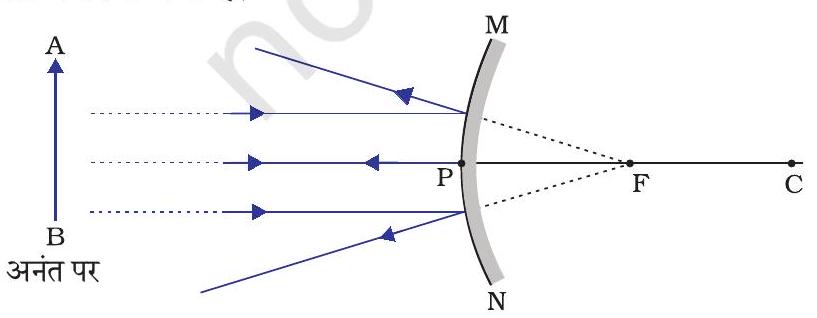
(a)
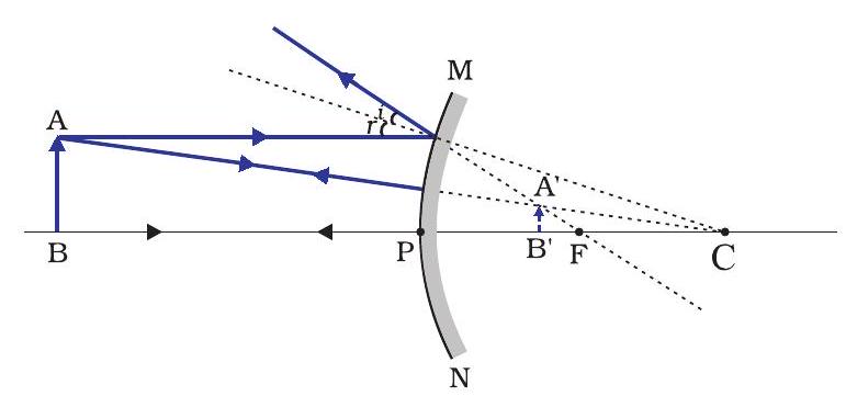
(b)
चित्र 9.8 उत्तल दर्पण द्वारा प्रतिबिंब बनना
सारणी 9.2 उत्तल दर्पण द्वारा बने प्रतिबिंब की प्रकृति, स्थिति तथा आपेक्षिक साइज़
| बिंब की स्थिति | प्रतिबिंब की स्थिति | प्रतिबिंब का साइज | प्रतिबिंब की प्रकृति |
|---|---|---|---|
| अनंत पर | फोकस $\mathrm{F}$ पर दर्पण के पीछे |
अत्यधिक छोटा, बिंदु के साइज़ का |
आभाषी तथा सीधा |
| अनंत तथा दर्पण के ध्रुव P के बीच |
P तथा $F$ के बीच | छोटा | आभाषी तथा सीधा |
अभी तक आपने समतल दर्पण, अवतल दर्पण तथा उत्तल दर्पण द्वारा प्रतिबिंब बनाने के बारे में अध्ययन किया है। इनमें से कौन-सा दर्पण किसी बड़े बिंब का पूरा प्रतिबिंब बनाएगा? आइए एक क्रियाकलाप द्वारा इसका अन्वेषण करें।
क्रियाकलाप 9.6
- समतल दर्पण में किसी दूरस्थ बिंब जैसे कोई दूरस्थ पेड़ का प्रतिबिंब देखिए।
- क्या आप पूर्ण-लंबाई (full-length) का प्रतिबिंब देख पाते हैं?
- विभिन्न साइज़ के समतल दर्पण लेकर प्रयोग दोहराइए। क्या आप दर्पण में बिंब का संपूर्ण प्रतिबिंब देख पाते हैं?
- इस क्रियाकलाप को अवतल दर्पण लेकर दोहराइए। क्या यह दर्पण बिंब की पूरी लंबाई का प्रतिबिंब बना पाता है?
- अब एक उत्तल दर्पण लेकर इस प्रयोग को दोहराइए। क्या आपको सफलता मिली? अपने प्रेक्षणों की कारण सहित व्याख्या कीजिए।
आप एक छोटे उत्तल दर्पण में किसी ऊँचे भवन/पेड़ का पूर्ण-लंबाई का प्रतिबिंब देख सकते हैं। आगरा किले की एक दीवार में ऐसा ही एक दर्पण ताजमहल की ओर लगा हुआ है। यदि आप कभी आगरा किला देखने जाएँ तो दीवार में लगे इस दर्पण में ताजमहल के पूर प्रतिबिंब को देखने का प्रयास करें। मकबरे को स्पष्टतः देखने के लिए आपको दीवार से सटी हुई छत पर उचित स्थान पर खड़ा होना होगा।
उत्तल दर्पणों के उपयोग
उत्तल दर्पणों का उपयोग सामान्यतः वाहनों के पश्च-दृश्य (wing) दर्पणों के रूप में किया जाता है। ये दर्पण वाहन के पार्श्व (side) में लगे होते हैं तथा इनमें ड्राइवर अपने पीछे के वाहनों को देख सकते हैं, जिससे वे सुरक्षित रूप से वाहन चला सकें। उत्तल दर्पणों को इसलिए भी प्राथमिकता देते हैं, क्योंकि ये सदैव सीधा प्रतिबिंब बनाते हैं, यद्यपि वह छोटा होता है। इनका दृष्टि-क्षेत्र भी बहुत अधिक है, क्योंकि ये बाहर की ओर वक्रित होते हैं। अतः समतल दर्पण की तुलना में उत्तल दर्पण ड्राइवर को अपने पीछे के बहुत बड़े क्षेत्र को देखने में समर्थ बनाते हैं।
प्रश्न
1. अवतल दर्पण के मुख्य फोकस की परिभाषा लिखिए।
Show Answer
#missing2. एक गोलीय दर्पण की वक्रता त्रिज्या $20 \mathrm{~cm}$ है। इसकी फोकस दूरी क्या होगी?
Show Answer
#missing3. उस दर्पण का नाम बताइए, जो बिंब का सीधा तथा आवर्धित प्रतिबिंब बना सके।
Show Answer
#missing4. हम वाहनों में उत्तल दर्पण को पश्च-दृश्य दर्पण के रूप में वरीयता क्यों देते हैं?
Show Answer
#missing9.2.3 गोलीय दर्पणों द्वारा परावर्तन के लिए चिह्न परिपाटी
गोलीय दर्पणों द्वारा प्रकाश के परावर्तन पर विचार करते समय हम एक निश्चित चिह्न परिपाटी का पालन करेंगे, जिसे नई कार्तीय चिह्न परिपाटी कहते हैं। इस परिपाटी में दर्पण के ध्रुव (P) (चित्र 9.9) को मूल बिंदु मानते हैं। दर्पण के मुख्य अक्ष को निर्देशांक पद्धति का $x$-अक्ष ( $\left.x^{\prime}\right)$ लिया जाता है। यह परिपाटी निम्नलिखित प्रकार की है-
(i) बिंब सदैव दर्पण के बाईं ओर रखा जाता है। इसका अर्थ है कि दर्पण पर बिंब से प्रकाश बाईं ओर से आपतित होता है।
(ii) मुख्य अक्ष के समांतर सभी दूरियाँ दर्पण के ध्रुव से मापी जाती हैं।
(iii) मूल बिंदु के दाईं ओर (+ $\mathrm{x}$-अक्ष के अनुदिश) मापी गई सभी दूरियाँ धनात्मक मानी जाती हैं, जबकि मूल बिंदु के बाईं ओर (- $\mathrm{x}$-अक्ष के अनुदिश) मापी गई दूरियाँ ऋणात्मक मानी जाती हैं।
(iv) मुख्य अक्ष के लंबवत तथा ऊपर की ओर ( $+\mathrm{y}$-अक्ष के अनुदिश) मापी जाने वाली दूरियाँ धनात्मक मानी जाती हैं।
(v) मुख्य अक्ष के लंबवत तथा नीचे की ओर (- y-अक्ष के अनुदिश) मापी जाने वाली दूरियाँ
ऊपर वर्णित नयी कार्तीय चिह्न परिपाटी आपके संदर्भ के लिए चित्र 9.9 में दर्शाई गई है। यह चिह्न परिपाटी दर्पण का सूत्र प्राप्त करने तथा संबंधित आंकिक प्रश्नों को हल करने के लिए प्रयुक्त की गई है।
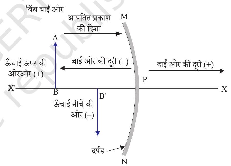
चित्र 9.9 गोलीय दर्पणों के लिए नयी कार्तीय चिन्ह परिपाटी ॠणात्मक मानी जाती हैं।
9.2.4 दर्पण सूत्र तथा आवर्धन
गोलीय दर्पण में इसके ध्रुव से बिंब की दूरी, बिंब दूरी $(u)$ कहलाती है। दर्पण के ध्रुव से प्रतिबिंब की दूरी, प्रतिबिंब दूरी $(v)$ कहलाती है। आपको पहले ही ज्ञात है कि ध्रुव से मुख्य फोकस की दूरी, फोकस दूरी $(f)$ कहलाती है। इन तीनों राशियों के बीच एक संबंध है, जिसे दर्पण सूत्र द्वारा प्रस्तुत किया जाता है।
इस सूत्र को निम्नलिखित प्रकार से व्यक्त करते हैं-
$$\frac{1}{v}+\frac{1}{u}=\frac{1}{f} \tag {9.1}$$
यह संबंध सभी प्रकार के गोलीय दर्पणों के लिए तथा बिंब की सभी स्थितियों के लिए मान्य हैं। प्रश्नों को हल करते समय, जब आप दर्पण सूत्र में $u, v, f$ तथा $R$ के मान प्रतिस्थापित करें तो आपको नई कार्तीय चिह्न परिपाटी का प्रयोग करना चाहिए।
आवर्धन
गोलीय दर्पण द्वारा उत्पन्न आवर्धन वह आपेक्षिक विस्तार है, जिससे ज्ञात होता है कि कोई प्रतिबिंब बिंब की अपेक्षा कितना गुना आवर्धित है। इसे प्रतिबिंब की ऊँचाई तथा बिंब की ऊँचाई के अनुपात रूप में व्यक्त किया जाता है।
यदि $h$ बिंब की ऊँचाई हो तथा $h^{\prime}$ प्रतिबिंब की ऊँचाई हो तो गोलीय दर्पण द्वारा उत्पन्न आवर्धन $(m)$ प्राप्त होगा।
$$ \begin{align*} & m=\frac{\text { प्रतिबिंब की ऊँचाई }\left(h^{\prime}\right)}{\text { बिंब की ऊँचाई }(h)} \\ & m=\frac{h^{\prime}}{h} \tag{9.2} \end{align*} $$
आवर्धन $m$ बिंब दूरी $(u)$ तथा प्रतिबिंब दूरी $(v)$ से भी संबंधित है। इसे व्यक्त किया जाता है-
$$ \begin{equation*} \text { आवर्धन }(m)=\frac{h}{h}=-\frac{v}{u} \tag{9.3} \end{equation*} $$
ध्यान दीजिए, बिंब की ऊँचाई धनात्मक ली जाती है, क्योंकि बिंब प्रायः मुख्य अक्ष के ऊपर रखा जाता है। आभासी प्रतिबिंबों के लिए बिंब की ऊँचाई धनात्मक लेनी चाहिए। तथापि वास्तविक प्रतिबिंबों के लिए इसे ऋणात्मक लेना चाहिए। आवर्धन के मान में ऋणात्मक चिह्न से ज्ञात होता है कि प्रतिबिंब वास्तविक है। आवर्धन के मान में धनात्मक चिह्न बताता है कि प्रतिबिंब आभासी है।
उदाहरण 9.1
किसी ऑटोमोबाइल में पीछे का दृश्य देखने के लिए उपयोग होने वाले उत्तल दर्पण की वक्रता त्रिज्या $3.00 \mathrm{~m}$ है। यदि एक बस इस दर्पण से $5.00 \mathrm{~m}$ की दूरी पर स्थित है तो प्रतिबिंब की स्थिति, प्रकृति तथा साइज़ ज्ञात कीजिए।
हल
वक्रता त्रिज्या, $R=+3.00 \mathrm{~m}$;
बिंब-दूरी, $u=-5.00 \mathrm{~m}$;
प्रतिबिंब-दूरी, $v=$ ?
प्रतिबिंब की ऊँचाई, $h^{\prime}=$ ?
फोकस दूरी $f=R / 2=+\frac{3.00 \mathrm{~m}}{2}=+1.50 \mathrm{~m}$ (क्योंकि उत्तल दर्पण का मुख्य फ़ोकस दर्पण के पीछे है।)
क्योंकि $\frac{1}{v}+\frac{1}{u}=\frac{1}{f}$
या $\frac{1}{v}=\frac{1}{f}-\frac{1}{u}=+\frac{1}{1.50}-\frac{1}{(-5.00)}=\frac{1}{1.50}+\frac{1}{5.00}$
$=\frac{5.00+1.50}{7.50}$
$v=\frac{+7.50}{6.50}=+1.15 \mathrm{~m}$
प्रतिबिंब दर्पण के पीछे $1.15 \mathrm{~m}$ की दूरी पर है।
आवर्धन, $m=\frac{h^{\prime}}{h}=-\frac{v}{u}=-\frac{1.15 \mathrm{~m}}{-5.00 \mathrm{~m}}$
$$ =+0.23 $$
प्रतिबिंब आभासी, सीधा तथा साइज़ में बिंब से छोटा ( 0.23 गुना) है।
उदाहरण 9.2
कोई $4.0 \mathrm{~cm}$ साइज़ का बिंब किसी $15.0 \mathrm{~cm}$ फोकस दूरी के अवतल दर्पण से $25.0 \mathrm{~cm}$ दूरी पर रखा है। दर्पण से कितनी दूरी पर किसी परदे को रखा जाए कि स्पष्ट प्रतिबिंब प्राप्त हो? प्रतिबिंब की प्रकृति तथा साइज़ ज्ञात कीजिए।
हल
बिंब-साइज़, $h=+4.0 \mathrm{~cm}$;
बिंब-दूरी, $u=-25.0 \mathrm{~cm}$;
फोकस दूरी $f=-15.0 \mathrm{~cm}$;
प्रतिबिंब-दूरी, $v=$ ?
प्रतिबिंब-साइज़, $h^{\prime}=$ ?
समीकरण (9.1) से
$ \begin{aligned} & \frac{1}{v}+\frac{1}{u}=\frac{1}{f} \\ & \text{ या, } \frac{1}{v}=\frac{1}{f}-\frac{1}{u}=\frac{1}{-15.0}-\frac{1}{-25.0}=-\frac{1}{15.0}+\frac{1}{25.0} \end{aligned} $
या $\frac{1}{v}=\frac{-5.0+3.0}{75.0}=\frac{-2.0}{75.0}$ या, $\mathrm{v}=-37.5 \mathrm{~cm}$
परदे को दर्पण के सामने $37.5 \mathrm{~cm}$ दूरी पर रखना चाहिए। प्रतिबिंब वास्तविक है।
इसी प्रकार, आवर्धन, $m=\frac{h^{\prime}}{h}=-\frac{v}{u}$
या $h^{\prime}=-\frac{v h}{u}=-\frac{(-37.5 \mathrm{~cm})(+4.0 \mathrm{~cm})}{(-25.0 \mathrm{~cm})}$
प्रतिबिंब की ऊँचाई, $h^{\prime}=-6.0 \mathrm{~cm}$
प्रतिबिंब उलटा तथा आवर्धित है।
प्रश्न
1. उस उत्तल दर्पण की फोकस दूरी ज्ञात कीजिए, जिसकी वक्रता-त्रिज्या $32 \mathrm{~cm}$ है।
Show Answer
#missing2. कोई अवतल दर्पण आमने-सामने $10 \mathrm{~cm}$ दूरी पर रखे किसी बिंब का तीन गुणा आवर्धित (बड़ा) वास्तविक प्रतिबिंब बनाता है। प्रतिबिंब दर्पण से कितनी दूरी पर है।
Show Answer
#missing9.3 प्रकाश का अपवर्तन
किसी पारदर्शी माध्यम में प्रकाश सरल रेखा में गमन करता प्रतीत होता है। जब प्रकाश एक पारदर्शी माध्यम से दूरे में प्रवेश करता है तो क्या होता है? क्या यह अब भी सरल रेखा में चलता है या अपनी दिशा बदलता है? हम अपने दिन-प्रतिदिन के कुछ अनुभवों को दोहराएँगे।
आपने देखा होगा कि पानी से भरे किसी टैंक अथवा ताल या पोखर की तली उठी हुई प्रतीत होती है। इसी प्रकार, जब कोई मोटा काँच का स्लैब (सिल्ली) किसी मुद्रित सामग्री पर रखा जाता है, तो काँच के स्लैब के ऊपर से देखने पर अक्षर उठे हुए प्रतीत होते हैं। ऐसा क्यों होता है? क्या आपने किसी काँच के बर्तन में रखे पानी में किसी पेंसिल को आंशिक रूप से डूबे देखा है? यह वायु तथा पानी के अंतरपृष्ठ पर (अर्थात पानी की ऊपरी सतह पर) टेढ़ी प्रतीत होती है। आपने देखा होगा कि पानी से भरे किसी काँच के बर्तन में रखे नींब पार्श्व (side) से देखने पर अपने वास्तविक साइज़ से बड़े प्रतीत होते हैं। इन अनुभवों की व्याख्या आप किस प्रकार करेंगे?
आइए, पानी में आंशिक रूप से डूबी पेंसिल के मुड़े होने की घटना पर विचार करें। पेंसिल के पानी में डूबे भाग से आपके पास पहुँचने वाला प्रकाश, पेंसिल के पानी से बाहर के भाग की तुलना में भिन्न दिशा से आता हुआ प्रतीत होता है। इसी कारण पेंसिल मुड़ी हुई प्रतीत होती है। इन्ही कारणों से, जब अक्षरों के ऊपर काँच का स्लैब रखकर देखते हैं तो वे उठे हुए प्रतीत होते हैं।
यदि पानी के स्थान पर हम कोई अन्य द्रव जैसे किरोसिन या तारपीन का तेल प्रयोग करें, क्या तब भी पेंसिल उतनी ही मुड़ी हुई दिखेगी? यदि हम काँच के स्लैब को पारदर्शी प्लास्टिक के स्लैब से प्रतिस्थापित कर दें, क्या तब भी अक्षर उसी ऊँचाई तक उठे प्रतीत होंगे? आप देखेंगे कि अलग-अलग माध्यमों के युग्मों के लिए इन प्रभावों का विस्तार अलग-अलग है। ये प्रेक्षण सूचित करते हैं कि प्रकाश सभी माध्यमों में एक ही दिशा में गमन नहीं करता। ऐसा प्रतीत होता है कि जब प्रकाश एक माध्यम से दूसरे माध्यम में तिरछा होकर जाता है तो दूसरे माध्यम में इसके संचरण की दिशा परिवर्तित हो जाती है। इस परिघटना को विस्तार से कुछ क्रियाकलाप करके समझें।
क्रियाकलाप 9.7
- पानी से भरी एक बाल्टी की तली पर एक सिक्का रखिए।
- अपनी आँख को पानी के ऊपर, किसी पार्श्व (side) में रखकर सिक्के को एक बार में उठाने का प्रयत्न कीजिए। क्या आप सिक्का उठाने में सफल हो पाते हैं?
- इस क्रियाकलाप को दोहराइए। आप इसे एक बार में करने में क्यों सफल नहीं हो पाए थे?
- अपने मित्रों से इसे करने के लिए कहिए। उनके साथ अपने अनुभव की तुलना कीजिए।
क्रियाकलाप 9.8
- किसी मेज़ पर एक बड़ा उथला कटोरा रखकर उसकी तली में एक सिक्का रखिए।
- कटोरे से धीर-धीरे दूर हटिए। जब सिक्का ठीक दिखाई देना बंद हो जाए तो रूक जाइए।
- अपने मित्र से सिक्के को विक्षुब्ध किए बगैर कटोरे में पानी डालने को कहिए।
- अपनी स्थिति से सिक्के को देखते रहिए। क्या सिक्का उसी स्थिति से पुनः दिखाई देने लगता है? यह कैसे संभव हो पाता है?
कटोरे में पानी डालने पर सिक्का फिर से दिखलाई देने लगता है। प्रकाश के अपवर्तन के कारण सिक्का अपनी वास्तविक स्थिति से थोड़ा-सा ऊपर उठा हुआ प्रतीत होता है।
क्रियाकलाप 9.9
- मेज़ पर रखे एक सफ़ेद कागज़ की शीट पर एक मोटी सीधी रेखा खींचिए।
- इस रेखा के ऊपर एक काँच का स्लैब इस प्रकार रखिए कि इसकी एक कोर इस रेखा से कोई कोण बनाए।
- स्लैब के नीचे आए रेखा के भाग को पार्श्व (side) से देखिए। आप क्या देखते हैं? क्या काँच के स्लैब के नीचे की रेखा कोरों (edges) के पास मुड़ी हुई प्रतीत होती है?
- अब काँच के स्लैब को इस प्रकार रखिए कि यह रेखा के अभिलंबवत हो। अब आप क्या देखते हैं? क्या काँच के स्लैब के नीचे रेखा का भाग मुड़ा हुआ प्रतीत होता है?
- रेखा को काँच के स्लैब के ऊपर से देखिए। क्या स्लैब के नीचे रेखा का भाग उठा हुआ प्रतीत होता है? ऐसा क्यों होता है?
9.3.1 काँच के आयताकार स्लैब से अपवर्तन
काँच के स्लैब से प्रकाश के अपवर्तन की परिघटना को समझने के लिए आइए, एक क्रियाकलाप करें।
क्रियाकलाप 9.10
- एक ड्राइंग बोर्ड पर सफ़ेद कागज़ की एक शीट, ड्राइंग पिनों की सहायता से लगाइए।
- शीट के ऊपर बीच में काँच का एक आयताकार स्लैब रखिए।
- पेंसिल से स्लैब की रूपरेखा खींचिए। इस रूपरेखा का नाम $\mathrm{ABCD}$ रखते हैं।
- चार एकसमान ऑलपिन लीजिए।
- दो पिनें, मान लीजिए $\mathrm{E}$ तथा $\mathrm{F}$ ऊध्र्वाधरतः इस प्रकार लगाइए कि पिनों को मिलाने वाली रेखा कोर $\mathrm{AB}$ से कोई कोण बनाती हुई हो।
- पिन $\mathrm{E}$ तथा $\mathrm{F}$ के प्रतिबिंबों को विपरीत फलक से देखिए। दूसरी दो पिनों, माना $\mathrm{G}$ तथा $\mathrm{H}$, को इस प्रकार लगाइए कि ये पिनें एवं $\mathrm{E}$ तथा $\mathrm{F}$ के प्रतिबिंब एक सीधी रेखा पर स्थित हों।
- पिनों तथा स्लैब को हटाइए।
- पिनों $\mathrm{E}$ तथा $\mathrm{F}$ की नोकों (tip) की स्थितियों को मिलाइए तथा इस रेखा को $\mathrm{AB}$ तक बढ़ाइए। मान लीजिए $\mathrm{EF}, \mathrm{AB}$ से बिंदु $\mathrm{O}$ पर मिलती है। इसी प्रकार पिनों $\mathrm{G}$ तथा $\mathrm{H}$ की नोकों की स्थितियों को मिलाइए तथा इस रेखा को कोर $\mathrm{CD}$ तक बढ़ाइए। मान लीजिए $\mathrm{HG}, \mathrm{CD}$ से $\mathrm{O}^{\prime}$ पर मिलती है।
- $\mathrm{O}$ तथा $\mathrm{O}^{\prime}$ को मिलाइए। $\mathrm{EF}$ को भी $\mathrm{P}$ तक बढ़ाइए, जैसा कि चित्र 9.10 में बिंदुकित रेखा द्वारा दर्शाया गया है।
इस क्रियाकलाप में आप नोट करेंगे कि प्रकाश किरण ने अपनी दिशा बिंदुओं $O$ तथा $O^{\prime}$ पर परिवर्तित की है। नोट कीजिए कि दोनों बिंदु $O$ तथा $O^{\prime}$ दोनों पारदर्शी माध्यमों को पृथक् करने वाले पृष्ठों पर स्थित हैं। $\mathrm{AB}$ के बिंदु $\mathrm{O}$ पर एक अभिलंब $\mathrm{NN}^{\prime}$ खींचिए तथा दूसरा अभिलंब $\mathrm{MM}^{\prime}, \mathrm{CD}$ के बिंदु $\mathrm{O}^{\prime}$ पर खीचिए। बिंदु $\mathrm{O}$ पर प्रकाश किरण विरल माध्यम से सघन माध्यम में अर्थात वायु से काँच में प्रवेश कर रही है। नोट कीजिए कि प्रकाश किरण अभिलंब की ओर झुक जाती है। $\mathrm{O}^{\prime}$ पर, प्रकाश किरण ने काँच से वायु में अर्थात सघन माध्यम से विरल माध्यम में प्रवेश किया है। प्रकाश किरण अभिलंब से दूर मुड़ जाती है। दोनों अपवर्तक सतहों $\mathrm{AB}$ तथा $\mathrm{CD}$ पर आपतन कोण तथा अपवर्तन कोण के मानों की तुलना कीजिए।
चित्र 9.10 में सतह $\mathrm{AB}$ पर एक किरण $\mathrm{EP}$ तिरछी आपतित है, जिसे आपतित किरण कहते हैं। $\mathrm{OO}^{\prime}$ अपवर्तित किरण है तथा $\mathrm{O}^{\prime} \mathrm{H}$ निर्गत किरण है। आप देख सकते हैं कि निर्गत किरण, आपतित किरण की दिशा के समानांतर है। ऐसा क्यों होता है? आयाताकार काँच के स्लैब के विपरीत फलकों $\mathrm{AB}$ (वायु-काँच अंतरापृष्ठ) तथा $\mathrm{CD}$ (काँच-वायु अतंरापृष्ठ) पर प्रकाश किरण के मुड़ने का परिमाण समान तथा विपरीत है। इसी कारण से निर्गत किरण, आपतित किरण के समानांतर निकलती है। तथापि, प्रकाश किरण में थोड़ा सा पार्शिवक विस्थापन होता है। यदि प्रकाश किरण दो माध्यमों के अंतरापृष्ठ पर अभिलंबवत आपतित हो तब क्या होगा? स्वयं करके ज्ञात कीजिए।
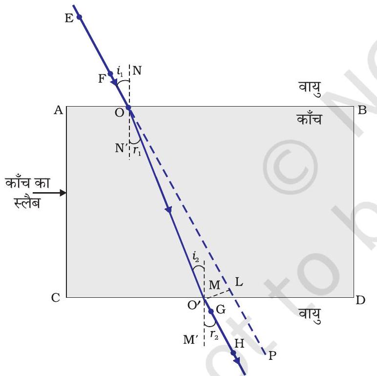
चित्र 9.10 आयताकार काँच के स्लैब से प्रकाश का अपवर्तन
अब आप प्रकाश के अपवर्तन से परिचित हैं। अपवर्तन प्रकाश के एक पारदर्शी माध्यम से दूसरे में प्रवेश करने पर प्रकाश की चाल में परिवर्तन के कारण होता है। प्रयोग दर्शाते हैं कि प्रकाश का अपवर्तन निश्चित नियमों के आधार पर होता है।
परावर्तन के नियम निम्नलिखित हैं-
(i) आपतित किरण, अपवर्तित किरण तथा दोनों माध्यमों को पृथक् करने वाले पृष्ठ के आपतन बिंदु पर अभिलंब सभी एक ही तल में होते हैं।
(ii) प्रकाश के किसी निश्चित रंग तथा निश्चित माध्यमों के युग्म के लिए आपतन कोण की ज्या (sine) तथा अपवर्तन कोण की ज्या (sine) का अनुपात स्थिर होता है। इस नियम को स्नेल का अपवर्तन का नियम भी कहते हैं। (यह कोण $0^{\circ}<i<90^{\circ}$ के लिए सत्य है) यदि $i$ आपतन कोण हो तथा $r$ अपवर्तन कोण हो तब
$$ \begin{equation*} \frac{\sin i}{\sin r}=\text { स्थिरांक } \tag{9.4} \end{equation*} $$
इस स्थिरांक के मान को दूसरे माध्यम का पहले माध्यम के सापेक्ष अपवर्तनांक (refractive index) कहते हैं। आइए, अपवर्तनांक के बारे में कुछ विस्तार से अध्ययन करें।
9.3.2 अपवर्तनांक
आप पहले ही अध्ययन कर चुके हैं कि जब प्रकाश की किरण तिरछी गमन करती हुई एक पारदर्शी माध्यम से दूसरे में प्रवेश करती है तो यह दूसरे माध्यम में अपनी दिशा परिवर्तित कर लेती है। किन्हीं दिए हुए माध्यमों के युग्म के लिए होने वाले दिशा परिवर्तन के विस्तार को अपवर्तनांक के रूप में भी व्यक्त किया जा सकता है, जो समीकरण (9.4) में दाएँ पक्ष में प्रकट होने वाला स्थिरांक है।
अपवर्तनांक को एक महत्वपूर्ण भौतिक राशि, विभिन्न माध्यमों में प्रकाश के संचरण की आपेक्षिक चाल, से संबद्ध किया जा सकता है। यह देखा गया है कि विभिन्न माध्यमों में प्रकाश अलग-अलग चालों से संचरित होता है। निर्वात में प्रकाश $3 \times 108 \mathrm{~m} / \mathrm{s}$ की चाल से चलता है, जो कि प्रकाश की किसी भी माध्यम में हो सकने वाली द्रुततम चाल है। वायु में प्रकाश की चाल निर्वात की अपेक्षा थोड़ी ही कम होती है। काँच या पानी में यह यथेष्ट रूप से घट जाती है। दो माध्यमों के युग्म के लिए अपवर्तनांक का मान दोनों माध्यमों में प्रकाश की चाल पर निर्भर है, जैसा कि नीचे दिया गया है।
चित्र 9.11 में दर्शाए अनुसार एक प्रकाश की किरण पर विचार करें, जो माध्यम 1 से माध्यम 2 में प्रवेश कर रही है। मान लीजिए कि प्रकाश की चाल माध्यम 1 में $v _{1}$ तथा माध्यम 2 में $v _{2}$ है। माध्यम 2 का माध्यम 1 के सापेक्ष अपवर्तनांक, माध्यम 1 में प्रकाश की चाल तथा माध्यम 2 में प्रकाश की चाल के अनुपात द्वारा व्यक्त करते हैं। इसे प्रायः संकेत $n _{21}$ से निरूपित करते हैं। इसे समीकरण के रूप में निम्नलिखित प्रकार से व्यक्त करते हैं-
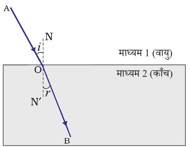
चित्र 9.11
$$ \begin{equation*} n _{21}=\frac{\text { माध्यम } 1 \text { में प्रकाश की चाल }}{\text { माध्यम } 2 \text { में प्रकाश की चाल }}=\frac{v _{1}}{v _{2}} \tag{9.5} \end{equation*} $$
इसी तर्क से, माध्यम 1 का माध्यम 2 के सापेक्ष अपवर्तनांक $n _{12}$ से निरूपित करते हैं। इसे व्यक्त किया जाता है-
$$ \begin{equation*} n _{12}=\frac{\text { माध्यम } 2 \text { में प्रकाश की चाल }}{\text { माध्यम } 1 \text { में प्रकाश की चाल }}=\frac{v _{2}}{v _{1}} \tag{9.6} \end{equation*} $$
यदि माध्यम 1 निर्वात या वायु है, तब माध्यम 2 का अपवर्तनांक निर्वात के सापेक्ष माना जाता है। यह माध्यम का निरपेक्ष अपवर्तनांक कहलाता है। यह केवल $n _{2}$ से निरूपित किया जाता है। यदि वायु में प्रकाश की चाल $c$ है तथा माध्यम में प्रकाश की चाल $v$ है तब माध्यम का अपवर्तनांक $\mathrm{n} _{\mathrm{m}}$ होगा
$$ \begin{equation*} \mathrm{n} _{\mathrm{m}}=\frac{\text { वायु में प्रकाश की चाल }}{\text { माध्यम में प्रकाश की चाल }}=\frac{c}{v} \tag{9.7} \end{equation*} $$
माध्यम का निरपेक्ष अपवर्तनांक केवल अपवर्तनांक कहलाता है। सारणी 9.3 में अनेक माध्यमों के अपवर्तनांक दिए गए हैं। सारणी से आपको ज्ञात होगा कि जल का अपवर्तनांक, $\mathrm{n} _{\mathrm{w}}=1.33$ है। इसका अर्थ है कि वायु में प्रकाश का वेग तथा जल में प्रकाश के वेग का अनुपात 1.33 है। इसी प्रकार क्राउन काँच का अपवर्तनांक, $\mathrm{n} _{\mathrm{g}}=1.52$ होता है। ऐसे आँकड़े अनेक स्थानों पर उपयोगी हैं। तथापि आपको इन आँकड़ों को कंठस्थ करने की आवश्यकता नहीं है।
सारणी 9.3: कुछ द्रव्यात्मक माध्यमों के निरपेक्ष अपवर्तनांक
| द्रव्यात्मक माध्यम | अपवर्तनांक | द्रव्यात्मक माध्यम | अपवर्तनांक |
|---|---|---|---|
| वायु | 1.0003 | कनाडा बालसम | 1.53 |
| बर्फ़ | 1.31 | खनिज नमक | 1.54 |
| जल | 1.33 | कार्बन डाइसल्फाइड | 1.63 |
| एल्कोहल | 1.36 | सघन फ्लिंट काँच | 1.65 |
| किरोसिन | 1.44 | रूबी (मणिक्य) | 1.71 |
| संगलित क्वार्ट्ज़ | 1.46 | नीलम | 1.77 |
| तारपीन का तेल | 1.47 | हीरा | 2.42 |
| बेंजीन | 1.50 | ||
| क्राउन काँच | 1.52 |
सारणी 9.3 से नोट कीजिए कि यह आवश्यक नहीं कि प्रकाशिक सघन माध्यम का द्रव्यमान घनत्व भी अधिक हो, उदाहरण के लिए- किरोसिन जिसका अपवर्तनांक जल से अधिक है, जल की अपेक्षा प्रकाशिक सघन है, यद्यपि इसका द्रव्यमान घनत्व जल से कम है।
यह भी जानिए!
किसी माध्यम की प्रकाश को अपवर्तित करने की क्षमता को इसके प्रकाशिक घनत्व के द्वारा भी व्यक्त किया जा सकता है। प्रकाशिक घनत्व का एक निश्चित संपृक्तार्थ (connotation) होता है। यह द्रव्यमान घनत्व के समान नहीं है। इस अध्याय में हम ‘विरल माध्यम’ तथा ‘सघन माध्यम’ शब्दों का प्रयोग कर रहे हैं। वास्तव में इनका अर्थ क्रमश: ‘प्रकाशिक विरल माध्यम’ तथा ‘प्रकाशिक सघन माध्यम’ है। हम कब कह सकते हैं कि कोई माध्यम दूसरे माध्यम की अपेक्षा प्रकाशिक सघन है? दो माध्यमों की तुलना करते समय, अधिक अपवर्तनांक वाला माध्यम दूसरे की अपेक्षा प्रकाशिक सघन है। दूसरा कम अपवर्तनांक वाला माध्यम प्रकाशिक विरल माध्यम है। विरल माध्यम में प्रकाश की चाल सघन माध्यम की अपेक्षा अधिक होती है। अतः विरल माध्यम से सघन माध्यम में गमन करने वाली प्रकाश की किरण धीमी हो जाती है तथा अभिलंब की ओर झुक जाती है। जब ये सघन माध्यम से विरल माध्यम में गमन करती है तो इसकी चाल बढ़ जाती है तथा यह अभिलंब से दूर हट जाती है।
प्रश्न
1. वायु में गमन करती प्रकाश की एक किरण जल में तिरछी प्रवेश करती है। क्या प्रकाश किरण अभिलंब की ओर झुकेगी अथवा अभिलंब से दूर हटेगी? बताइए क्यों?
Show Answer
#missing2. प्रकाश वायु से 1.50 अपवर्तनांक की काँच की प्लेट में प्रवेश करता है। काँच में प्रकाश की चाल कितनी है? निर्वात में प्रकाश की चाल $3 \times 10^{8} \mathrm{~m} / \mathrm{s}$ है।
Show Answer
#missing3. सारणी 9.3 से अधिकतम प्रकाशिक घनत्व के माध्यम को ज्ञात कीजिए। न्यूनतम प्रकाशिक घनत्व के माध्यम को भी ज्ञात कीजिए।
Show Answer
#missing4. आपको किरोसिन, तारपीन का तेल तथा जल दिए गए हैं। इनमें से किसमें प्रकाश सबसे अधिक तीव्र गति से चलता है? सारणी 9.3 में दिए गए आँकड़ों का उपयोग कीजिए।
Show Answer
#missing5. हीरे का अपवर्तनांक 2.42 है। इस कथन का क्या अभिप्राय है?
Show Answer
#missing9.3.3 गोलीय लेंसों द्वारा अपवर्तन
आपने किसी घड़ीसाज़ को बहुत छोटे पुरज़ों को देखने के लिए छोटे आवर्धक लेंस का उपयोग करते देखा होगा। क्या कभी आपने आवर्धक लेंस के पृष्ठ को अपने हाथों से छूकर देखा है? क्या इसका पृष्ठ समतल है या वक्रित है? क्या यह बीच से मोटा है या किनारों से? चश्मों में हम लेंसों का ही उपयोग करते हैं। घड़ीसाज़ के आवर्धक में भी लेंस लगा होता है। लेंस क्या है? यह प्रकाश किरणों को किस प्रकार मोड़ता है? इस अनुच्छेद में हम इसी विषय में अध्ययन करेंगे।
(a)
(b)
चित्र : 9.12 (a) उत्तल लेंस की अभिसारी क्रिया (b) अवतल लेंस की अपसारी क्रिया
दो पृष्ठों से घिरा हुआ कोई पारदर्शी माध्यम, जिसका एक या दोनों पृष्ठ गोलीय हैं, लेंस कहलाता है। इसका अर्थ यह है कि लेंस का कम-से-कम एक पृष्ठ गोलीय होता है। ऐसे लेंसों में दूसरा पृष्ठ समतल हो सकता है। किसी लेंस में बाहर की ओर उभरे दो गोलीय पृष्ठ हो सकते हैं। ऐसे लेंस को द्वि-उत्तल लेंस कहते हैं। इसे केवल उत्तल लेंस भी कहते हैं। यह किनारों की अपेक्षा बीच से मोटा होता है। उत्तल लेंस प्रकाश किरणों को चित्र 9.12 (a) में दर्शाए अनुसार अभिसरित करता है।
इसीलिए उत्तल लेंसों को अभिसारी लेंस भी कहते हैं। इसी प्रकार एक द्वि-अवतल लेंस अंदर की ओर वक्रित दो गोलीय पृष्ठों से घिरा होता है। यह बीच की अपेक्षा किनारों से मोटा होता है। ऐसे लेंस प्रकाश किरणों को चित्र 9.12 (b) में दर्शाए अनुसार अपसरित करते हैं। ऐसे लेंसों को अपसारी लेंस कहते हैं। द्वि-अवतल लेंस प्रायः अवतल लेंस भी कहलाता है।
किसी लेंस में चाहे वह उत्तल हो अथवा अवतल, दो गोलीय पृष्ठ होते हैं। इनमें से प्रत्येक पृष्ठ एक गोले का भाग होता है। इन गोलों के केंद्र लेंस के वक्रता केंद्र कहलाते हैं। लेंस का वक्रता केंद्र प्रायः अक्षर $\mathrm{C}$ द्वारा निरूपित किया जाता है, क्योंकि लेंस के दो वक्रता केंद्र हैं। इसलिए, इन्हें $\mathrm{C} _{1}$ तथा $\mathrm{C} _{2}$ द्वारा निरूपित किया जाता है। किसी लेंस के दोनों वक्रता केंद्रों से गुजरने वाली एक काल्पनिक सीधी रेखा लेंस का मुख्य अक्ष कहलाती है। लेंस का केंद्रीय बिंदु इसका प्रकाशिक केंद्र कहलाता है। इसे प्रायः अक्षर $\mathrm{O}$ से निरूपित करते हैं।
लेंस के प्रकाशिक केंद्र से गुजरने वाली प्रकाश किरण बिना किसी विचलन के निर्गत होती है। गोलीय लेंस की वृत्ताकार रूपरेखा का प्रभावी व्यास इसका द्वारक (aperture) कहलाता है। इस अध्याय में अपने विवेचन में हम केवल उन्हीं लेंसों तक सीमित रहेंगे, जिनका द्वारक इनकी वक्रता त्रिज्या से बहुत छोटा है और दोनों वक्रता केंद्र प्रकाशिक केंद्र से समान दूरी पर होते हैं। ऐसे लेंस छोटे द्वारक के पतले लेंस कहलाते हैं। जब किसी लेंस पर समांतर किरणें आपतित होती हैं तो क्या होता है? इसे समझने के लिए आइए, एक क्रियाकलाप करें।
क्रियाकलाप 9.11
चेतावनी— इस क्रियाकलाप को करते समय अथवा अन्यथा भी सूर्य की ओर सीधे या लेंस से न देखें। यदि आप ऐसा करेंगे तो आपकी आँखों को क्षति हो सकती है।
- एक उत्तल लेंस को अपने हाथ में पकड़िए। इसे सूर्य की ओर निर्दिष्ट कीजिए।
- सूर्य के प्रकाश को एक कागज़ की शीट पर फोकसित कीजिए। सूर्य का एक तीक्ष्ण चमकदार प्रतिबिंब प्राप्त कीजिए।
- कागज़ तथा लेंस को कुछ समय के लिए उसी स्थिति में पकड़े रखिए। कागज़ को देखते रहिए। क्या होता है? ऐसा क्यों होता है? क्रियाकलाप 9.2 के अपने अनुभवों को स्मरण कीजिए।
कागज़ सुलगने लगता है और धुआँ उत्पन्न होता है। कुछ समय पश्चात यह आग भी पकड़ सकता है। ऐसा क्यों होता है? सूर्य से आने वाली प्रकाश की किरणें समानांतर होती हैं। लेंस द्वारा यह किरणें एक तीक्ष्ण चमकदार बिंदु के रूप में कागज़ पर अभिकेंद्रित कर दी जाती हैं। वास्तव में, कागज़ की शीट पर यह चमकदार बिंदु सूर्य का प्रतिबिंब है। एक बिंदु पर सूर्य के प्रकाश का संकेंद्रण ऊष्मा उत्पन्न करता है। इसके कारण कागज़ जलने लगता है।
अब हम एक लेंस के मुख्य अक्ष के समानांतर प्रकाश किरणों पर विचार करते हैं। जब आप प्रकाश की ऐसी किरणों को किसी लेंस से गुज़ारते हैं तो क्या होता है? एक उत्तल लेंस के लिए इसे चित्र 9.12 (a) में तथा अवतल लेंस के लिए चित्र 9.12 (b) में दर्शाया गया है।
चित्र 9.12 (a) को ध्यानपूर्वक देखिए। उत्तल लेंस पर मुख्य अक्ष के समानांतर प्रकाश की बहुत सी किरणें आपतित हैं। ये किरणें लेंस से अपवर्तन के पश्चात मुख्य अक्ष पर एक बिंदु पर अभिसरित हो जाती हैं। मुख्य अक्ष पर यह बिंदु लेंस का मुख्य फोकस कहलाता है। आइए, अब एक अवतल लेंस का व्यवहार देखें।
चित्र 9.12 (b) को ध्यानपूर्वक देखिए। अवतल लेंस पर मुख्य अक्ष के समानांतर प्रकाश की अनेक किरणें आपतित हो रही हैं। ये किरणें लेंस से अपवर्तन के पश्चात मुख्य अक्ष के एक बिंदु से अपसरित होती प्रतीत होती हैं। मुख्य अक्ष पर यह बिंदु अवतल लेंस का मुख्य फोकस कहलाता है।
यदि आप किसी लेंस के विपरीत पृष्ठ से समांतर किरणों को गुजरने दें तो आपको पहले से विपरीत दिशा में दूसरा मुख्य फोकस प्राप्त होगा। मुख्य फोकस को निरूपित करने के लिए प्रायः अक्षर $\mathrm{F}$ का प्रयोग होता है। तथापि, किसी लेंस में दो मुख्य फोकस होते हैं। इन्हें $\mathrm{F} 1$ तथा $\mathrm{F} 2$ द्वारा निरूपित किया जाता है। किसी लेंस के मुख्य फोकस की प्रकाशिक केंद्र से दूरी फोकस दूरी कहलाती है। फोकस दूरी को अक्षर ’ $\mathrm{f}$ ’ द्वारा निरूपित किया जाता है। आप किसी उत्तल लेंस की फोकस दूरी किस प्रकार ज्ञात कर सकते हैं? क्रियाकलाप 9.11 को स्मरण कीजिए। इस क्रियाकलाप में लेंस की स्थिति तथा सूर्य के प्रतिबिंब की स्थिति के बीच की दूरी लेंस की सन्निकट (लगभग) फोकस दूरी बताती है।
9.3.4 लेंसों द्वारा प्रतिबिंब बनना
लेंस प्रतिबिंब कैसे बनाते हैं? लेंस प्रकाश के अपवर्तन द्वारा प्रतिबिंब बनाते हैं। उन प्रतिबिंबों की प्रकृति क्या है? आइए, पहले उत्तल लेंस के लिए इसका अध्ययन करें।
क्रियाकलाप 9.12
- एक उत्तल लेंस लीजिए। क्रियाकलाप 9.11 में वर्णित विधि द्वारा इसकी सन्निकट फोकस दूरी ज्ञात कीजिए।
- एक लंबी मेज़ पर चॉक का प्रयोग करके पाँच समानांतर सीधी रेखाएँ इस प्रकार खींचिए कि किन्हीं दो उत्तरोतर रेखाओं के बीच की दूरी लेंस की फोकस दूरी के बराबर हो।
- लेंस को एक लेंस-स्टैंड पर लगाइए। इसे मध्य रेखा पर इस प्रकार रखिए कि लेंस का प्रकाशिक केंद्र इस रेखा पर स्थित हो।
- लेंस के दोनों ओर दो रेखाएँ क्रमशः लेंस के $\mathrm{F}$ तथा $2 \mathrm{~F}$ के तदनुरूपी होंगी। इन्हें उचित अक्षरों द्वारा अंकित कीजिए, जैसे-क्रमशः $2 \mathrm{~F} _{1}, \mathrm{~F} _{1}, \mathrm{~F} _{2}$ तथा $2 \mathrm{~F} _{2}$ ।
- एक जलती हुई मोमबत्ती को बाईं ओर, $2 \mathrm{~F} _{1}$ से काफ़ी दूर रखिए। लेंस के विपरीत दिशा में रखे एक परदे पर इसका स्पष्ट एवं तीक्ष्ण प्रतिबिंब बनाइए।
- प्रतिबिंब की प्रकृति, स्थिति तथा आपेक्षिक साइज़ नोट कीजिए।
- इस क्रियाकलाप में बिंब को $2 \mathrm{~F} _{1}$ से थोड़ा दूर, $\mathrm{F} _{1}$ तथा $2 \mathrm{~F} _{1}$ के बीच, $\mathrm{F} _{1}$ पर तथा $\mathrm{F} _{1}$ और $\mathrm{O}$ के बीच रख कर दोहराइए। अपने प्रेक्षणों को नोट कीजिए तथा सारणीबद्ध कीजिए।
बिंब की विभिन्न स्थितियों के लिए उत्तल लेंस द्वारा बनाए गए प्रतिबिंब की प्रकृति, स्थिति तथा आपेक्षिक साइज़ का संक्षिप्त विवरण सारणी 9.4 में दिया गया है।
सारणी 9.4 बिंब की विभिन्न स्थितियों के लिए उत्तल लेंस द्वारा बने प्रतिबिंब की प्रकृति, स्थिति तथा आपेक्षिक साइज़
| बिंब की स्थिति | प्रतिबिंब की स्थिति | प्रतिबिंब का आपेक्षिक साइज़ | प्रतिबिंब की प्रकृति |
|---|---|---|---|
| अनंत पर | फोकस $\mathrm{F} _{2}$ पर | अत्यधिक छोटा, बिंदु आकार | वास्तविक तथा उलटा |
| $2 \mathrm{~F} _{1}$ से परे | $\mathrm{F} _{2}$ तथा $2 \mathrm{~F} _{2}$ के बीच | छोटा | वास्तविक तथा उलटा |
| $2 \mathrm{~F} _{1}$ पर | $2 \mathrm{~F} _{2}$ पर | समान साइज़ | वास्तविक तथा उलटा |
| $\mathrm{F} _{1}$ तथा $2 \mathrm{~F} _{1}$ के बीच फोकस $\mathrm{F} _{1}$ पर |
$2 \mathrm{~F} _{2}$ से परे अनंत पर | बड़ा (विवर्धित) असीमित रूप से बड़ा अथवा अत्यधिक विवर्धित |
वास्तविक तथा उलटा |
| फोकस F1 तथा प्रकाशिक केंद्र O के बीच |
जिस ओर बिंब है लेंस के उसी ओर |
बड़ा (विवर्धित) | आभासी तथा सीधा |
आइए, अब किसी अवतल लेंस द्वारा बने प्रतिबिंब की प्रकृति, स्थिति तथा आपेक्षिक साइज़ का एक क्रियाकलाप द्वारा अध्ययन करें।
क्रियाकलाप 9.13
- एक अवतल लेंस लीजिए। इसे एक लेंस स्टैंड पर रखिए।
- लेंस के एक ओर एक जलती हुई मोमबत्ती को रखिए।
- लेंस के दूसरी ओर से प्रतिबिंब का प्रेक्षण कीजिए। प्रतिबिंब को यदि संभव हो तो परदे पर प्राप्त करने का प्रयत्न कीजिए। यदि ऐसा संभव न हो तो प्रतिबिंब को लेंस में से सीधे ही देखिए।
- प्रतिबिंब की प्रकृति, आपेक्षिक साइज़ तथा सन्निकट स्थिति नोट कीजिए।
- मोमबत्ती को लेंस से दूर ले जाइए। प्रतिबिंब के साइज़ में परिवर्तन नोट कीजिए। जब मोमबत्ती को लेंस से बहुत दूर रखा जाता है तो प्रतिबिंब के साइज़ पर क्या प्रभाव पड़ता है?
उपरोक्त क्रियाकलाप का संक्षिप्त विवरण सारणी 9.5 में दिया गया है।
सारणी 9.5 बिंब की विभिन्न स्थितियों के लिए अवतल लेंस द्वारा बने प्रतिबिंब की प्रकृति, स्थिति तथा आपेक्षिक साइज़
| बिंब की स्थिति | प्रतिबिंब की स्थिति | प्रतिबिंब का आपेक्षिक साइज़ | प्रतिबिंब की प्रकृति |
|---|---|---|---|
| अनंत पर | फोकस $\mathrm{F} _{1}$ पर | अत्यधिक छोटा, बिंदु आकार छोटा | आभासी तथा सीधा |
| अनंत तथा लेंस के प्रकाशिक केंद्र $\mathrm{O}$ |
फोकस $\mathrm{F} _{1}$ तथा प्रकाशिक केंद्र $\mathrm{O}$ के बीच |
आभासी तथा सीधा |
इस क्रियाकलाप से आप क्या निष्कर्ष निकालते हैं? अवतल लेंस सदैव एक आभासी, सीधा तथा छोटा प्रतिबिंब बनाएगा, चाहे बिंब कहीं भी स्थित हो।
9.3.5 किरण आरेखों के उपयोग द्वारा लेंसों से प्रतिबिंब बनना
हम किरण आरेखों के उपयोग द्वारा लेंसों से प्रतिबिंबों के बनने को निरूपित कर सकते हैं। किरण आरेख लेंसों में बने प्रतिबिंबों की प्रकृति, स्थिति तथा आपेक्षिक साइज़ का अध्ययन करने में भी हमारी सहायता करेंगे। लेंसों में किरण आरेख बनाने के लिए गोलीय दर्पणों की भाँति हम निम्नलिखित में से किन्हीं दो किरणों पर विचार कर सकते हैं।
(i) बिंब से, मुख्य अक्ष के समानांतर आने वाली कोई प्रकाश किरण उत्तल लेंस से अपवर्तन के पश्चात चित्र 9.13 (a) में दर्शाए अनुसार लेंस के दूसरी ओर मुख्य फोकस से गुज़रेगी। अवतल लेंस की स्थिति में प्रकाश किरण चित्र 9.13 (b) में दर्शाए अनुसार लेंस के उसी ओर स्थित मुख्य फोकस से अपसरित होती प्रतीत होती है।
(ii) मुख्य फोकस से गुज़रने वाली प्रकाश किरण, उत्तल लेंस से अपवर्तन के पश्चात मुख्य अक्ष के समानांतर निर्गत होगी। इसे चित्र 9.14 (a) में दर्शाया गया है। अवतल लेंस के मुख्य फोकस पर मिलती प्रतीत होने वाली प्रकाश किरण, अपवर्तन के पश्चात मुख्य अक्ष के समानांतर निर्गत होगी। इसे चित्र 9.14 (b) में दर्शाया गया है।
(iii) लेंस के प्रकाशिक केंद्र से गुज़रने वाली प्रकाश किरण अपवर्तन के पश्चात बिना किसी विचलन के निर्गत होती है। इसे चित्र 9.15 (a) तथा 9.15 (b) में दर्शाया गया है।
चित्र 9.16 में उत्तल लेंस द्वारा किसी बिंब की कुछ स्थितियों में, प्रतिबिंब बनने को किरण आरेखों द्वारा दर्शाया गया है। चित्र 9.17 में अवतल लेंस द्वारा बिंब की विभिन्न स्थितियों में प्रतिबिंब बनने को किरण आरेखों द्वारा दर्शाया गया है।
चित्र 9.16 उत्तल लेंस द्वारा बिंब की विभिन्न स्थितियों के लिए प्रतिबिंब की स्थिति, साइज़ एवं प्रकृति
चित्र 9.17 अवतल लेंस द्वारा बने प्रतिबिंब की प्रकृति, स्थिति तथा साइज़
9.3.6 गोलीय लेंसों के लिए चिह्न-परिपाटी
लेंसों के लिए, हम गोलीय दर्पणों जैसी ही चिह्न-परिपाटी अपनाएँगे। दरियों के चिह्नों के निर्धारण के लिए हम यहाँ भी उन्हीं नियमों को अपनाएँगे। केवल, जहाँ दर्पणों में सभी दूरियाँ उनके ध्रुवों से नापी जाती हैं वहाँ लेंसों में सभी माप उनके प्रकाशिक केंद्र से लिए जाते हैं। परिपाटी के अनुसार उत्तल लेंस की फोकस दूरी धनात्मक होती है, जबकि अवतल लेंस की फोकस दूरी ऋणात्मक होती है। आपको $u, v$ तथा $f$, बिंब ऊँचाई $h$ तथा प्रतिबिंब ऊँचाई $h^{\prime}$ के मान में उचित चिह्नों का चयन करने में सावधानी बरतनी चाहिए।
9.3.7 लेंस सूत्र तथा आवर्धन
जिस प्रकार हमने गोलीय दर्पणों के लिए सूत्र ज्ञात किया था, उसी प्रकार गोलीय लेंसों के लिए भी लेंस सूत्र स्थापित किया गया है। यह सूत्र बिंब दूरी $(u)$, प्रतिबिंब दूरी $(v)$ तथा फोकस दूरी $(f)$ के बीच संबंध प्रदान करता है। लेंस सूत्र व्यक्त किया जाता है-
$$ \begin{equation*} \frac{1}{v}-\frac{1}{u}=\frac{1}{f} \tag{9.8} \end{equation*} $$
उपरोक्त लेंस सूत्र व्यापक है तथा किसी भी गोलीय लेंस के लिए, सभी स्थितियों में मान्य है। लेंसों से संबंधित प्रश्नों को हल करने के लिए लेंस सूत्र में आंकिक मान प्रतिस्थापित करते समय विभिन्न राशियों के उचित चिह्नों का ध्यान रखना चाहिए।
आवर्धन
किसी लेंस द्वारा उत्पन्न आवर्धन, किसी गोलीय दर्पण द्वारा उत्पन्न आवर्धन की ही भाँति प्रतिबिंब की ऊँचाई तथा बिंब की ऊँचाई के अनुपात के रूप में परिभाषित किया जाता है। आवर्धन को अक्षर $m$ द्वारा निरूपित किया जाता है। यदि बिंब की ऊँचाई $h$ हो तथा लेंस द्वारा बनाए गए प्रतिबिंब की ऊँचाई $h^{\prime}$ हो, तब लेंस द्वारा उत्पन्न आवर्धन प्राप्त होगा-
$$ \begin{equation*} m=\frac{\text { प्रतिबिंब की ऊँचाई }}{\text { बिंब की ऊँचाई }}=\frac{h^{\prime}}{h} \tag{9.9} \end{equation*} $$
लेंस द्वारा उत्पन्न आवर्धन, बिंब दूरी $u$ तथा प्रतिबिंब-दूरी $v$ से भी संबंधित है। इस संबंध को व्यक्त करते हैं-
आवर्धन $(m)=\frac{h}{h}=\frac{v}{u}$
उदाहरण 9.3
किसी अवतल लेंस की फोकस दूरी $15 \mathrm{~cm}$ है। बिंब को लेंस से कितनी दूरी पर रखें कि इसके द्वारा बिंब का लेंस से $10 \mathrm{~cm}$ दूरी पर प्रतिबिंब बने? लेंस द्वारा उत्पन्न आवर्धन भी ज्ञात कीजिए।
हल
अवतल लेंस द्वारा सदैव ही आभासी, सीधा प्रतिबिंब उसी ओर बनता है, जिस ओर बिंब रखा होता है।
प्रतिबिंब-दूरी $v=-10 \mathrm{~cm}$
फोकस दूरी $f=-15 \mathrm{~cm}$
बिंब-दूरी $u=$ ?
क्योंकि $\frac{1}{v}-\frac{1}{u}=\frac{1}{f}$
या $\frac{1}{u}=\frac{1}{v}-\frac{1}{f}$
$\frac{1}{u}=\frac{1}{-10}-\frac{1}{(-15)}=-\frac{1}{10}+\frac{1}{15}$
या $\frac{1}{u}=\frac{-3+2}{30}=\frac{1}{-30}$
या $u=-30 \mathrm{~cm}$
इसी प्रकार बिंब की दूरी $30 \mathrm{~cm}$ है।,
आवर्धन, $m=\frac{v}{u}$
$m=\frac{-10 \mathrm{~cm}}{-30 \mathrm{~cm}}=\frac{1}{3} \simeq+0.33$
यहाँ धनात्मक चिह्न यह दर्शाता है कि प्रतिबिंब सीधा तथा आभासी है। प्रतिबिंब का साइज़ बिंब के साइज़ का एक-तिहाई है।
उदाहरण 9.4
कोई $2.0 \mathrm{~cm}$ लंबा बिंब $10 \mathrm{~cm}$ फोकस दूरी के किसी उत्तल लेंस के मुख्य अक्ष के लंबवत रखा है। बिंब की लेंस से दूरी $15 \mathrm{~cm}$ है। प्रतिबिंब की प्रकृति, स्थिति तथा साइज़ ज्ञात कीजिए। इसका आवर्धन भी ज्ञात कीजिए।
हल
बिंब की ऊँचाई $h=+2.0 \mathrm{~cm}$
फोकस दरी $f=+10 \mathrm{~cm}$
बिंब-दूरी $u=-15 \mathrm{~cm}$
प्रतिबिंब-दूरी $v=$ ?
प्रतिबिंब की ऊँचाई $h^{\prime}=$ ?
क्योंकि $\frac{1}{v}-\frac{1}{u}=\frac{1}{f}$
या, $\frac{1}{v}=\frac{1}{u}+\frac{1}{f}$
$\frac{1}{v}=\frac{1}{(-15)}+\frac{1}{10}=-\frac{1}{15}+\frac{1}{10}$
$\frac{1}{v}=\frac{-2+3}{30}=\frac{1}{30}$
या $v=+30 \mathrm{~cm}$
$v$ का धनात्मक चिह्न यह दर्शाता है कि प्रतिबिंब लेंस के प्रकाशिक केंद्र के दाईं ओर $30 \mathrm{~cm}$ दूरी पर बनता है। प्रतिबिंब वास्तविक तथा उलटा है।
आवर्धन, $m=\frac{h^{\prime}}{h}=\frac{v}{u}$
अथवा $h^{\prime}=h\left(\frac{v}{u}\right)$
प्रतिबिंब की ऊँचाई $h^{\prime}=(2.0)\left(+\frac{30}{-15}\right)=-4.0 \mathrm{~cm}$
आवर्धन $m=\frac{+30 \mathrm{~cm}}{-15 \mathrm{~cm}}=-2$
$m$ तथा $h^{\prime}$ के ऋणात्मक चिह्न यह दर्शाते हैं कि उपरोक्त वर्णन के अनुसार प्रतिबिंब उलटा तथा वास्तविक है। यह मुख्य अक्ष के नीचे बनता है। इस प्रकार एक वास्तविक उलटा तथा $4.0 \mathrm{~cm}$ लंबा प्रतिबिंब लेंस के दाईं ओर लेंस से $30 \mathrm{~cm}$ दूरी पर बनता है। यह प्रतिबिंब दोगुना विवर्धित है।
9.3.8 लेंस की क्षमता
आप जानते हैं कि किसी लेंस की प्रकाश किरणों को अभिसरित अथवा अपसरित करने की क्षमता उसकी फोकस दूरी पर निर्भर करती है, उदाहरण के लिए- कम फोकस दूरी का एक उत्तल लेंस प्रकाश किरणों को बड़े कोण से मोड़कर उन्हें प्रकाशिक केंद्र के निकट फोकसित कर देता है। इसी प्रकार, कम फोकस दूरी का एक अवतल लेंस अधिक फोकस दूरी के लेंस की अपेक्षा प्रकाश किरणों को अधिक अपसरित करता है। किसी लेंस द्वारा प्रकाश किरणों को अभिसरण या अपसरण करने की मात्रा (degree) को उसकी क्षमता के रूप में व्यक्त किया जाता है। इसे अक्षर $\mathrm{P}$ द्वारा निरूपित करते हैं। किसी $f$ फोकस दूरी के लेंस की क्षमता,
$$ \begin{equation*} \mathrm{P}=\frac{1}{f} \tag{9.11} \end{equation*} $$
लेंस की क्षमता का SI मात्रक ‘डाइऑप्टर’ (Dioptre) है। इसे अक्षर D द्वारा दर्शाया जाता है। यदि $f$ को मीटर में व्यक्त करें तो क्षमता को डाइऑप्टर में व्यक्त किया जाता है। इस प्रकार, 1 डाइऑप्टर उस लेंस की क्षमता है, जिसकी फोकस दूरी 1 मीटर हो। $1 \mathrm{D}=1 \mathrm{~m}^{-1}$ । आप नोट कर सकते हैं कि उत्तल लेंस की क्षमता धनात्मक तथा अवतल लेंस की क्षमता ॠणात्मक होती है।
चश्मा बनाने वाले जब संशोधी लेंस निर्धारित करते हैं तो उनकी क्षमता का उल्लेख करते हैं। मान लीजिए निर्धारित लेंस की क्षमता $+2.0 \mathrm{D}$ है। इसका अर्थ है कि निर्धारित लेंस उत्तल है और उसकी फोकस दूरी $+0.50 \mathrm{~m}$ है। इसी प्रकार, $-2.5 \mathrm{D}$ क्षमता के लेंस की फोकस दूरी -0.40 $\mathrm{m}$ होती है। यह लेंस अवतल होता है।
यह भी जानिए!
अनेक प्रकाशिक यंत्रों में कई लेंस लगे होते हैं। उन्हें प्रतिबिंब को अधिक आवर्धित तथा सुस्पष्ट बनाने के लिए संयोजित किया जाता है। इस प्रकार संपर्क में रखे लेंसों की कुल क्षमता $(P)$ उन लेंसों की पृथक-पृथक क्षमताओं $\left(P_1, P_2, P_3 \ldots\right.$ आदि), का बीजगणितीय योग होती है, जैसे- $P=P_1+P_2+P_3+\ldots$
चश्मा बनाने वालों के लिए, लेंसों की फोकस दूरी के स्थान पर क्षमताओं का उपयोग करना काफ़ी सुविधाजनक है। आँखें टेस्ट करते समय चश्मा बनाने वाला ज्ञात क्षमता वाले संशोधी लेंसों के अनेक अलग-अलग संयोजनों को संपर्क में रखकर, चश्मों को टेस्ट करने वाले फ्रेम के अंदर रखता है। चश्मा बनानेवाला आवश्यक लेंस की क्षमता की गणना सरल बीजगणितीय योग के द्वारा कर लेता है, उदाहरण के लिए— + $2.0 \mathrm{D}$ तथा $+0.25 \mathrm{D}$ क्षमता वाले दो लेंसों का संयोजन + 2.25 D क्षमता के एकल लेंस के तुल्य है। लेंसों की क्षमताओं की योज्यता के इस गुणधर्म का उपयोग, एकल लेंस द्वारा बने प्रतिबिंबों में कुछ दोषों को कम करने में किया जा सकता है। कई लेंसों को एक-दूसरे के संपर्क में रखकर बनाए गए लेंस निकायों का उपयोग सामान्यतः कैमरों के लेंस तथा सूक्ष्मदर्शियों एवं दूरदर्शकों के लेंसों के डिजाइइन में किया जाता है।
प्रश्न
1. किसी लेंस की 1 डाइऑप्टर क्षमता को परिभाषित कीजिए।
Show Answer
#missing2. कोई उत्तल लेंस किसी सुई का वास्तविक तथा उलटा प्रतिबिंब उस लेंस से $50 \mathrm{~cm}$ दूर बनाता है। यह सुई, उत्तल लेंस के सामने कहाँ रखी है, यदि इसका प्रतिबिंब उसी साइज़ का बन रहा है, जिस साइज़ का बिंब है। लेंस की क्षमता भी ज्ञात कीजिए।
Show Answer
#missing3. $2 \mathrm{~m}$ फोकस दूरी वाले किसी अवतल लेंस की क्षमता ज्ञात कीजिए।
Show Answer
#missingआपने क्या सीखा
- प्रकाश सरल रेखाओं में गमन करता प्रतीत होता है।
- दर्पण तथा लेंस वस्तुओं के प्रतिबिंब बनाते हैं। बिंब की स्थिति के अनुसार प्रतिबिंब वास्तविक अथवा आभासी हो सकते हैं।
- सभी प्रकार के परावर्ती पृष्ठ परावर्तन के नियमों का पालन करते हैं। अपवर्ती पृष्ठ अपवर्तन के नियमों का पालन करते हैं।
- गोलीय दर्पणों तथा लेंसों के लिए नई कार्तीय चिह्न-परिपाटी अपनाई जाती है।
- दर्पण सूत्र $\frac{1}{\mathrm{~V}}+\frac{\mathrm{l}}{\mathrm{u}}=\frac{\mathrm{l}}{\mathrm{f}}$, बिंब-दूरी $(\mathrm{u})$, प्रतिबिंब-दूरी $(v)$ तथा गोलीय दर्पण की फोकस दूरी $(f)$ में संबंध दर्शाता है।
- किसी गोलीय दर्पण की फोकस दूरी उसकी वक्रता त्रिज्या की आधी होती है।
- किसी गोलीय दर्पण द्वारा उत्पन्न आवर्धन, प्रतिबिंब की ऊँचाई तथा बिंब की ऊँचाई का अनुपात होता है।
- सघन माध्यम से विरल माध्यम में तिरछी गमन करने वाली कोई प्रकाश किरण अभिलंब से परे झुक जाती है। विरल माध्यम से सघन माध्यम में तिरछी गमन करने वाली प्रकाश किरण अभिलंब की ओर झुक जाती है।
- निर्वात में प्रकाश $3 \times 10^{8} \mathrm{~m} \mathrm{~s}^{-1}$ की अत्यधिक चाल से गमन करता है। विभिन्न माध्यमों में प्रकाश की चाल भिन्न-भिन्न होती है।
- किसी पारदर्शी माध्यम का अपवर्तनांक प्रकाश की निर्वात में चाल तथा प्रकाश की माध्यम में चाल का अनुपात होता है।
- किसी आयताकार काँच के स्लैब के प्रकरण में, अपवर्तन वायु-काँच अंतरापृष्ठ एवं काँच-वायु अंतरापृष्ठ दोनों पर होता है। निर्गत किरण आपतित किरण की दिशा के समांतर होती है।
- लेंस सूत्र : $\frac{1}{\mathrm{v}}+\frac{\mathrm{l}}{\mathrm{u}}=\frac{1}{\mathrm{f}}$, बिंब-दूरी $(\mathrm{u})$, प्रतिबिंब-दूरी $(v)$ तथा गोलीय लेंस की फोकस दूरी $(f)$ में संबंध दर्शाता है।
- किसी लेंस की क्षमता उसकी फोकस दूरी का व्युत्क्रम होती है। लेंस की क्षमता का SI मात्रक डाइऑप्टर है।
अभ्यास
1. निम्न में से कौन-सा पदार्थ लेंस बनाने के लिए प्रयुक्त नहीं किया जा सकता?
(a) जल
(b) काँच
(c) प्लास्टिक
(d) मिट्टी
Show Answer
#missing2. किसी बिंब का अवतल दर्पण द्वारा बना प्रतिबिंब आभासी, सीधा तथा बिंब से बड़ा पाया गया। वस्तु की स्थिति कहाँ होनी चाहिए?
(a) मुख्य फोकस तथा वक्रता केंद्र के बीच
(b) वक्रता केंद्र पर
(c) वक्रता केंद्र से परे
(d) दर्पण के ध्रुव तथा मुख्य फोकस के बीच
Show Answer
#missing3. किसी बिंब का वास्तविक तथा समान साइज़ का प्रतिबिंब प्राप्त करने के लिए बिंब को उत्तल लेंस के सामने कहाँ रखें?
(a) लेंस के मुख्य फोकस पर
(b) फोकस दूरी की दोगुनी दूरी पर
(c) अनंत पर
(d) लेंस के प्रकाशिक केंद्र तथा मुख्य फोकस के बीच
Show Answer
#missing4. किसी गोलीय दर्पण तथा किसी पतले गोलीय लेंस दोनों की फोकस दूरियाँ $-15 \mathrm{~cm}$ हैं। दर्पण तथा लेंस संभवतः हैं-
(a) दोनों अवतल
(b) दोनों उत्तल
(c) दर्पण अवतल तथा लेंस उत्तल
(d) दर्पण उत्तल तथा लेंस अवतल
Show Answer
#missing5. किसी दर्पण से आप चाहे कितनी ही दूरी पर खड़े हों, आपका प्रतिबिंब सदैव सीधा प्रतीत होता है। संभवतः दर्पण है-
(a) केवल समतल
(b) केवल अवतल
(c) केवल उत्तल
(d) या तो समतल अथवा उत्तल
Show Answer
#missing6. किसी शब्दकोष (dictionary) में पाए गए छोटे अक्षरों को पढ़ते समय आप निम्नलिखित में से कौन-सा लेंस पसंद करेंगे?
(a) $50 \mathrm{~cm}$ फोकस दूरी का एक उत्तल लेंस
(b) $50 \mathrm{~cm}$ फोकस दूरी का एक अवतल लेंस
(c) $5 \mathrm{~cm}$ फोकस दूरी का एक उत्तल लेंस
(d) $5 \mathrm{~cm}$ फोकस दूरी का एक अवतल लेंस
Show Answer
#missing7. $15 \mathrm{~cm}$ फोकस दूरी के एक अवतल दर्पण का उपयोग करके हम किसी बिंब का सीधा प्रतिबिंब बनाना चाहते हैं। बिंब का दर्पण से दूरी का परिसर (range) क्या होना चाहिए? प्रतिबिंब की प्रकृति कैसी है? प्रतिबिंब बिंब से बड़ा है अथवा छोटा? इस स्थिति में प्रतिबिंब बनने का एक किरण आरेख बनाइए।
Show Answer
#missing8. निम्नलिखित स्थितियों में प्रयुक्त दर्पण का प्रकार बताइए-
(a) किसी कार का अग्र-दीप (हेड-लाइट)
(b) किसी वाहन का पार्श्व/पश्च-दृश्य दर्पण
(c) सौर भट्टी अपने उत्तर की कारण सहित पुष्टि कीजिए।
Show Answer
#missing9. किसी उत्तल लेंस का आधा भाग काले कागज़ से ढक दिया गया है। क्या यह लेंस किसी बिंब का पूरा प्रतिबिंब बना पाएगा? अपने उत्तर की प्रयोग द्वारा जाँच कीजिए। अपने प्रेक्षणों की व्याख्या कीजिए।
Show Answer
#missing10. $5 \mathrm{~cm}$ लंबा कोई बिंब $10 \mathrm{~cm}$ फोकस दूरी के किसी अभिसारी लेंस से $25 \mathrm{~cm}$ दूरी पर रखा जाता है। प्रकाश किरण-आरेख खींचकर बनने वाले प्रतिबिंब की स्थिति, साइज़ तथा प्रकृति ज्ञात कीजिए।
Show Answer
#missing11. $15 \mathrm{~cm}$ फोकस दूरी का कोई अवतल लेंस किसी बिंब का प्रतिबिंब लेंस से $10 \mathrm{~cm}$ दूरी पर बनाता है। बिंब लेंस से कितनी दूरी पर स्थित है? किरण आरेख खींचिए।
Show Answer
#missing12. $15 \mathrm{~cm}$ फोकस दूरी के किसी उत्तल दर्पण से कोई बिंब $10 \mathrm{~cm}$ दूरी पर रखा है। प्रतिबिंब की स्थिति तथा प्रकृति ज्ञात कीजिए।
Show Answer
#missing13. एक समतल दर्पण द्वारा उत्पन्न आवर्धन +1 है। इसका क्या अर्थ है?
Show Answer
#missing14. $5.0 \mathrm{~cm}$ लंबाई का कोई बिंब $30 \mathrm{~cm}$ वक्रता त्रिज्या के किसी उत्तल दर्पण के सामने $20 \mathrm{~cm}$ दूरी पर रखा गया है। प्रतिबिंब की स्थिति, प्रकृति तथा साइज़ ज्ञात कीजिए।
Show Answer
#missing15. $7.0 \mathrm{~cm}$ साइज़ का कोई बिंब $18 \mathrm{~cm}$ फोकस दूरी के किसी अवतल दर्पण के सामने $27 \mathrm{~cm}$ दूरी पर रखा गया है। दर्पण से कितनी दूरी पर किसी परदे को रखें कि उस पर वस्तु का स्पष्ट फोकसित प्रतिबिंब प्राप्त किया जा सके। प्रतिबिंब का साइज़ तथा प्रकृति ज्ञात कीजिए।
Show Answer
#missing16. उस लेंस की फोकस दूरी ज्ञात कीजिए, जिसकी क्षमता $-2.0 \mathrm{D}$ है। यह किस प्रकार का लेंस है?
Show Answer
#missing17. कोई डॉक्टर +1.5 D क्षमता का संशोधक लेंस निर्धारित करता है। लेंस की फोकस दूरी ज्ञात कीजिए। क्या निर्धारित लेंस अभिसारी है अथवा अपसारी?


