moving-charges-and-magnetism Question 39
Question: Q. 3. (i) Show how Biot-Savart’s law can be alternatively expressed in the form of Ampere’s circuital law. Use this law to obtain the expression for the magnetic field inside a solenoid of length ’
Draw the magnetic field lines of a finite solenoid carrying current
(ii) A straight horizontal conducting rod of length
Find the magnitude and direction of the magnetic field which should be set up in order that the tension in the wire is zero.
U] A [Delhi I, II, III 2015]
Show Answer
Solution:
Ans. (i) A current carrying surface with small line elements of length
This form is known as Ampere’s circuital law. 1/2
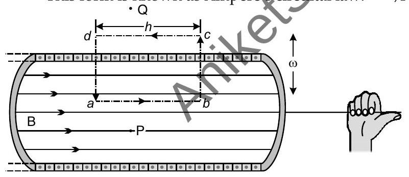
Let ’
Hence, total enclosed current
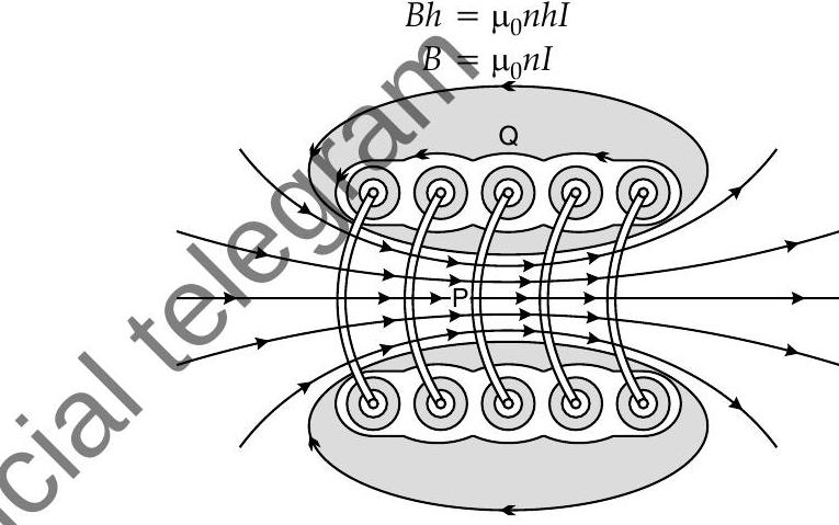
(ii)
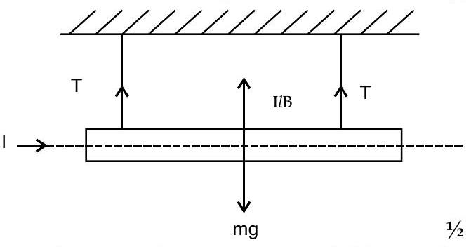
As per the given figure, magnetic field must be vertically inwards, to make tension zero, (If a student shows current in opposite direction the magnetic field should be set up vertically upwards).
For tension to be zero,
TOPIC-3
Torque and Galvanometer
Revision Notes
Torque experienced by a current loop in uniform magnetic field
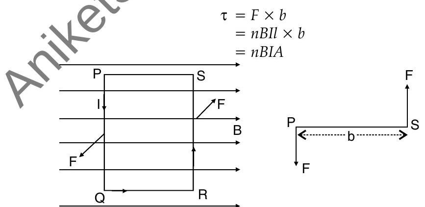
In a rectangular loop of length
, breadth with current flowing through it in a uniform magnetic field of induction where angle is between the normal and in direction of magnetic field, then the torque experienced will be :
where,
Further,
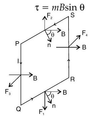
Torque will be maximum when the coil is parallel to magnetic field and will be zero when coil is perpendicular to magnetic field.
In vector notation, torque
experienced will be
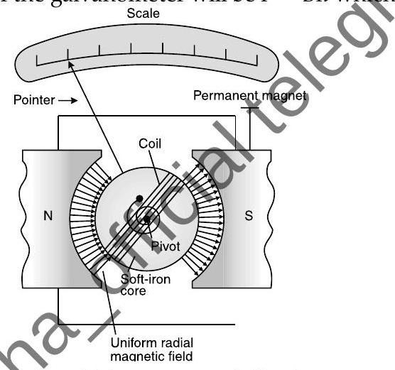
Moving coil galvanometer
It is an instrument used for detection and measurement of small electric currents
In this, when a current carrying coil is suspended in uniform magnetic field, it experiences a torque which rotates the coil.
The force experienced by each side of the galvanometer will be
which are opposite in direction.
Opposite and equal forces form the cquple which generates deflecting torque on the coil having number of turns
is given as :
In moving coil galvanometer, current in the coil will be directly proportional to the angle of the deflection of the coil,
Current sensitivity of galvanometer
Current sensitivity of galvanometer is the deflection produced when unit current passes through the galvanometer. A galvanometer is said to be sensitive if it produces large deflection for a small current.
Current Sensitivity,
Voltage sensitivity of galvanometer is the deflection per unit voltage given as
Voltage Sensitivity,
Increase in sensitivity of moving coil galvanometer depends on :
(i) number of turns
Conversion of galvanometer into ammeter
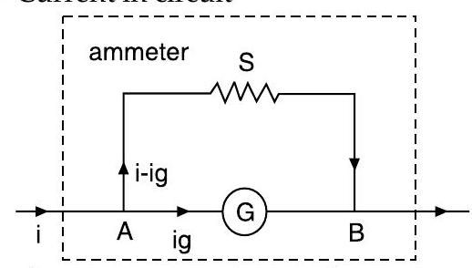
Galvanometer can be converted into ammeter by connecting a low resistance known as shunt in parallel with the galvanometer coil.
If
being the maximum current with full scale deflection that passes through galvanometer, then current through shunt resistance will be
where,
D Now effective resistance of ammeter will be :
Conversion of galvanometer into voltmeter
Voltmeter measures the potential difference between the two ends of a current carrying conductor.
Galvanometer can be converted to voltmeter by connecting high resistance in series with galvanometer coil.
As resistance
is connected in series with galvanometer, current through the galvanometer will be,
- Effective resistance of voltmeter is
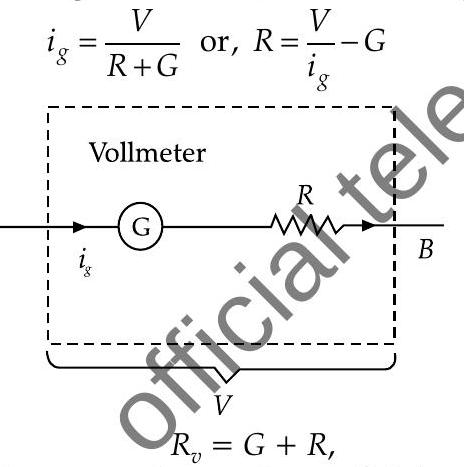 where,
Key Formulae
Force between two parallel wires
- Force between two moving charge particle
f. Very Short Answer Type Questions
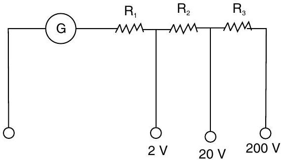
[II Q. 1. A multi-range voltmeter can be constructed by using the galvanometer circuit as shown. We want to construct a voltmeter that can measure
Detailed Answer :
From the question,
For
For
For
Answering Tips
- Sometimes students commit errors while substituting the values.


