alternating-currents Question 30
Question: Q. 6. (i) An
(ii) In a series
Show Answer
Solution:
Ans. (i) Try yourself similar Q. 5 Long Answer Type Question.
(ii) Power factor :
Power factor when capacitor
[CBSE Marking Scheme 2016]
[AI Q. 7. (i) With the help of a diagram, explain the principle and working of a device which produces current that reverses its direction after regular interyals of time.
(ii) If a charged capacitor
(a) In what form the capacitor and the inductor store energy?
(b) Write two reasons due to which the oscillations become damped.
R [CBSE SQP 2015]
OR
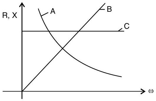
(i) Figure shows the variation of resistance and reactance versus angular frequency. Identify the curve which corresponds to inductive reactance and resistance.
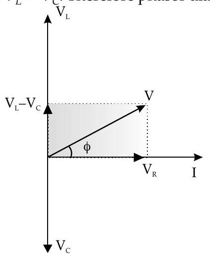
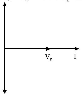
(ii) Show that series LCR circuit at resonance behaves as a purely resistive circuit. Compare the phase relation between current and voltage in series LCR circuit for (i)
(iii) What is an acceptor circuit and where it is used ?
U] [CBSE SQP 2015]
Ans. (i) AC generator
Diagram
1
Principle
1
Working
1
(ii) (a) Capacitor - electric field Inductor - magnetic field
(b) resistance of the circuit
Radio tuning
Radiation in the form of EM waves
OR
(i)
(ii) At resonance
Increase
Phasor diagrams
phase difference is
for 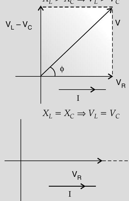
same phase, i.e.
(iii) Acceptor circuit : Series LCR circuit Radio tuning
Detailed Answer :
(i)
Basic elements of an
- Rectangular coil : Also called as armature
- Strong permanent magnets : Magnetic field is perpendicular of the axis of rotation of coil.
- Slip rings
- Brushes
Rotation of coil
Field Motion Armature coil clockwise
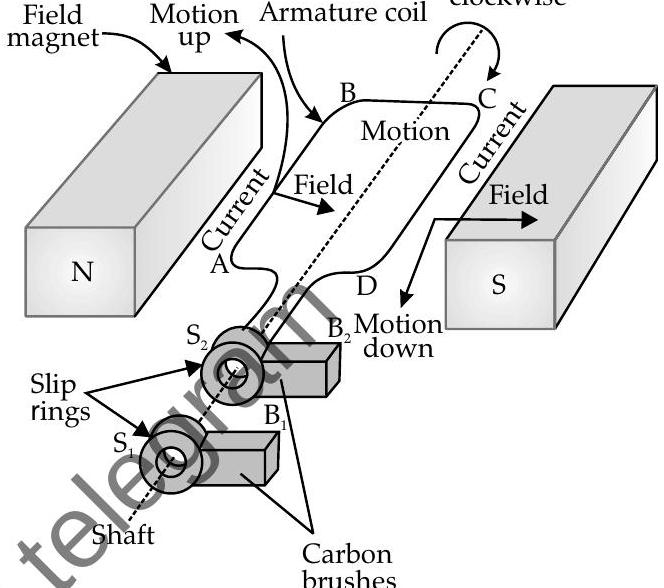
AC generator
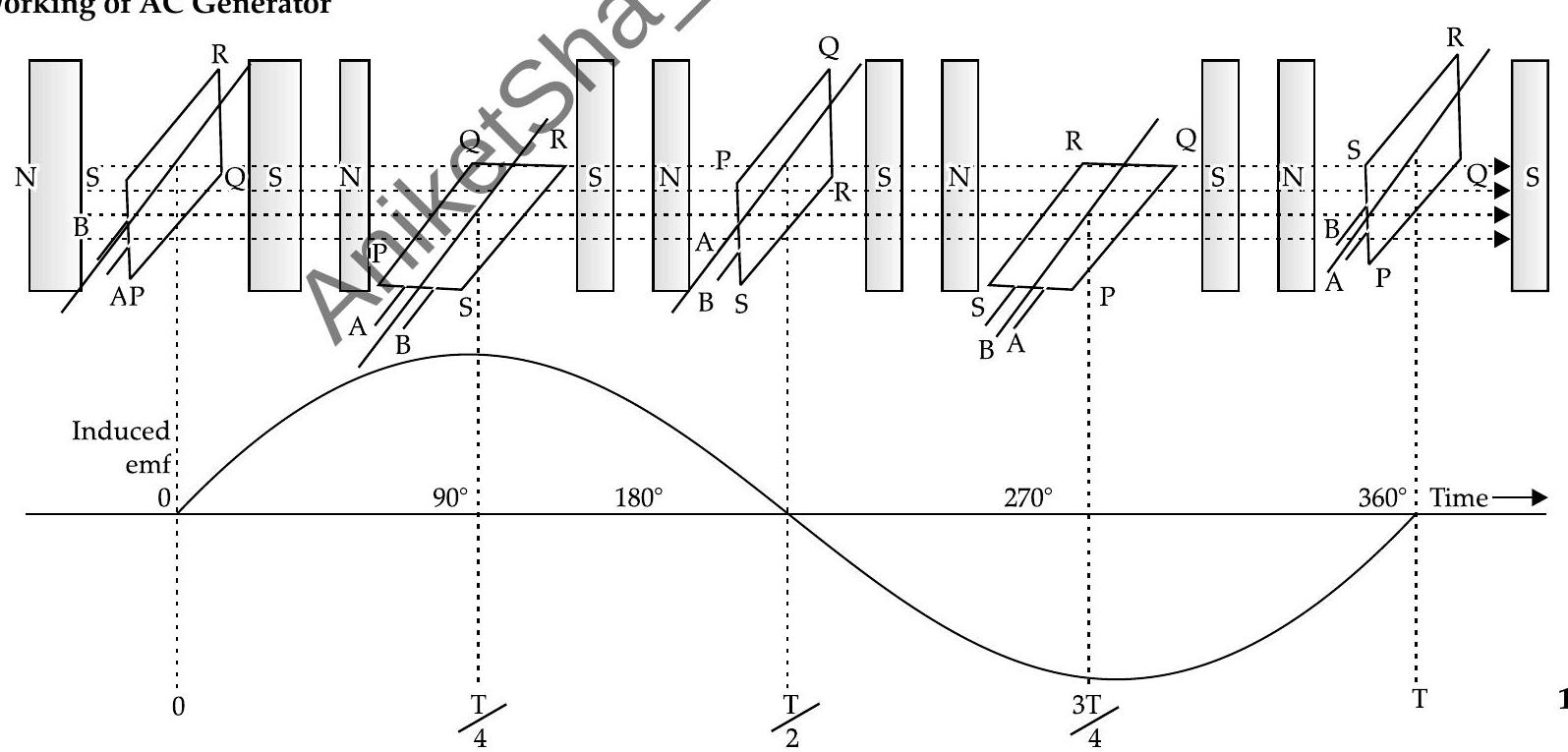
Principle : It is based on the principle of electromagnetic induction. That is, when a coil is rotated about an axis perpendicular to the direction of uniform magnetic field, an induced emf is produced across it.
Working of AC Generator
(ii) (a) The capacitor stores energy in the form of electric field and the inductor stores energy in the form of magnetic field.
(b) Oscillations become damped due to :
- Resistance of the circuit
- Radiation in the form of EM waves
(i) Curve
Therefore, impedance is given as :
Thus, series
For
Here,
For
(iii) Series resonance
They are widely used in the tuning mechanism of a radio or a TV.


