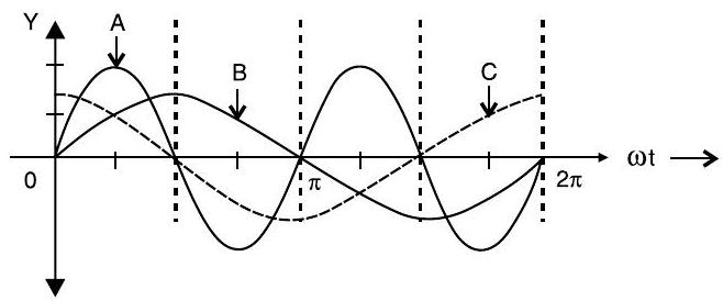
Question: Q. 2. A device ’ ’ is connected to an source sin . The variation of voltage, current and power in one cycle is shown in the following graph :
(i) Identify the device ’ ‘.
(ii) Which of the curves and represent the voltage, current and the power consumed in the circuit ? Justify your answer.
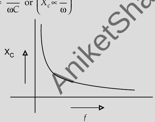
(iii) How does its impedance vary with frequency of the ac source? Show graphically.
(iv) Obtain an expression for the current in the circuit and its phase relation with voltage.
U[CBSE SQP 2017]
Show Answer
Solution:
Ans. (i) Identification
(ii) Identifying the curves Justification
(iii) Variation of Impedance with frequency Graph
(iv) Expression for current Phase relation
(i) The device is a capacitor
(ii) Curve voltage
Curve current
Curve power
Reason : The current leads the voltage in phase
by , for a capacitor.
(iii) or
(iv)
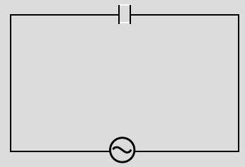
Current leads the voltage, in phase, by
[Note : If the student identifies the device as an Inductor but writes correct answer to parts (c) and (d) (in terms of an inductor), the student be given full marks for (only) these two parts]
[CBSE Marking Scheme 2017]
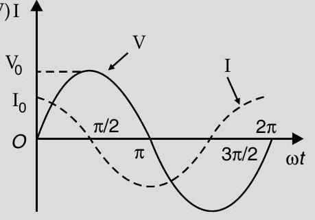
AT Q. 3. (i) An source generating a voltage is connected to a capacitor of capacitance . Find the expression of the current I flowing through it. Plot a graph of and versus to show that the current is ahead of the voltage.
(ii) A resistor of and a capacitor of are connected in series to a source. Calculate the current in the circuit and the rms voltage across the resistor and the capacitor. Why the algebraic sum of these voltages is more than the source voltage? A [CBSE SQP 2016]
Ans. (i)

(V)I
(ii)
Two voltages are out of phase, hence they are added vectorially.
[CBSE Marking Scheme 2016]


